Table of Contents
Advertisement
Quick Links
Advertisement
Table of Contents

Related Manuals for Altusen ALTUSEN KL1116


Summary of Contents for Altusen ALTUSEN KL1116
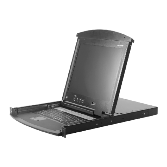
- Page 1 LCD KVM Switch KL1116 User Manual www.aten.com...
-
Page 2: Fcc Information
KL1116 User Manual FCC Information This is an FCC Class A product. In a domestic environment this product may cause radio interference in which case the user may be required to take adequate measures. This equipment has been tested and found to comply with the limits for a Class A digital device, pursuant to Part 15 of the FCC Rules. -
Page 3: User Information
KL1116 User Manual User Information Online Registration Be sure to register your product at our online support center: International http://support.aten.com North America ATEN TECH http://www.aten-usa.com/product_registration ATEN NJ http://support.aten.com Telephone Support For telephone support, call this number: International 886-2-8692-6959 North America... -
Page 4: Package Contents
Copyright © 2008 ATEN® International Co., Ltd. Manual Part No. PAPE-0253-2AXG Manual Date: 2008-07-30 Altusen and the Altusen logo are registered trademarks of ATEN International Co., Ltd. All rights reserved. All other brand names and trademarks are the registered property of their respective owners. -
Page 5: Table Of Contents
KL1116 User Manual Contents FCC Information ..........ii SJ/T 11364-2006. - Page 6 KL1116 User Manual LCD OSD Configuration ........22 The LCD Buttons.
- Page 7 KL1116 User Manual Chapter 6. The Firmware Upgrade Utility Preparation ..........48 Starting the Upgrade .
-
Page 8: About This Manual
KL1116 User Manual About This Manual This User Manual is provided to help you get the most from your KL1116 system. It covers all aspects of installation, configuration and operation. An overview of the information found in the manual is provided below. Overview Chapter 1, Introduction, introduces you to the KL1116 System. -
Page 9: Conventions
For information about all ALTUSEN products and how they can help you connect without limits, visit ALTUSEN on the Web or contact an ALTUSEN Authorized Reseller. Visit ALTUSEN on the Web for a list of locations and telephone numbers: International http://www.aten.com North America ATEN TECH http://www.aten-usa.com ATEN NJ http://www.aten.com... - Page 10 KL1116 User Manual This Page Intentionally Left Blank...
-
Page 11: Chapter 1 Introduction
Chapter 1 Introduction Overview The KL1116 KVM Switch is a control unit that allows access to multiple computers from a single KVM (keyboard, monitor, and mouse), console. Before the development of the Master View, the only way to control multiple computer configurations from a single console was through a complex and costly network system. - Page 12 KL1116 User Manual Access to any computer connected to the installation is easily accomplished either by means of a powerful, mouse driven, OSD (On Screen Display) menu system, or by entering Hotkey combinations from the keyboard. A convenient Auto Scan feature also permits automatic scanning and monitoring of the activities of all computers running on the installation one by one.
-
Page 13: Features
Chapter 1. Introduction Features Integrated KVM console with 15" or 17" LCD monitor - in a Hideaway™ housing. Hideaway™ housing is slightly less than 1U - with top and bottom clearance for smooth operation in a 1U high system rack. LCD Monitor component can slide independently of the keyboard/ touchpad component Space saving technology - two consoles (one bus) control up to 16... -
Page 14: Hardware Requirements
KL1116 User Manual Hardware Requirements Computers The integrated LCD monitor's maximum resolution is 1024 x 768 (15") or 1280 x 1024 (17"). Make sure that none of the computer resolution settings exceed the LCD monitor's maximum resolution. Cables Substandard cables may damage the connected devices or degrade overall performance. -
Page 15: Front View
Chapter 1. Introduction Front View Component Description Upper Pull to slide the LCD module out; push to slide the module in. Handle See item 7 in this table and Opening the Console, page 15 for more details on sliding the console in and out. LCD Display After sliding the LCD module out, flip up the cover to access the LCD monitor. - Page 16 KL1116 User Manual (Continued from previous page.) Component Description Port Press a switch to bring the KVM focus to the computer attached Switches to its corresponding port. See Manual Port Switching, page 24 and Port for details. LEDs Two Port LEDs are built into the Port Switches. The one on the left is the On Line LED;...
-
Page 17: Rear View
Chapter 1. Introduction Rear View Component Description Daisy-chain When Daisy-chaining units, the cable plugs in here. Port KVM Ports The cables that link to the computers plug in here. Note: The shape of these 15-pin connectors has been specifically modified so that only KVM cables designed to work with this switch can plug in (See Cables, page 4). - Page 18 KL1116 User Manual This Page Intentionally Left Blank...
-
Page 19: Chapter 2. Hardware Setup
Chapter 2 Hardware Setup 1. Important safety information regarding the placement of this device is provided on page 53. Please review it before proceeding. 2. Make sure that power to all the devices you will be connecting up have been turned off. You must unplug the power cords of any computers that have the Keyboard Power On function. - Page 20 KL1116 User Manual Optional mounting kits – including single person Easy Installation kits – are available with a separate purchase. See Optional Rack Mounting, page 60 for details. To rack mount the KL1116, do the following: 1. While one person positions the KL1116 in the rack and holds it in place, the second person loosely screws the front brackets to the rack.
-
Page 21: Single Stage Installation
Chapter 2. Hardware Setup Single Stage Installation In a Single Stage installation, there are no additional switches daisy chained down from the first unit. To set up a single stage installation, refer to the installation diagram on the next page (the numbers in the diagram correspond to the numbers of the installation steps), and do the following: 1. - Page 22 KL1116 User Manual Single Stage Installation Diagram...
-
Page 23: Daisy-Chain Installation
Chapter 2. Hardware Setup Daisy-chain Installation To control even more computers, up to 31 KH0116 units can be daisy-chained down from the KL1116. Note: It would be unnecessarily wasteful and expensive to use KL1116 switches for daisy-chaining since there is no point in having consoles on the chained switches. - Page 24 KL1116 User Manual (Continued from previous page.) b) Power up each daisy-chained station on the installation in turn (Second Station, then Third Station, etc.). Each KH0116 has an LED display on its front panel to indicate its Station ID (the Station ID for the First Stage unit (KL1116) is 01, the ID for the Second Stage unit (the first KH0116) is 02, the ID for the Third Stage unit is 03, etc.).
-
Page 25: Chapter 3. Basic Operation
Chapter 3 Basic Operation Opening the Console The KL1116's console consists of two modules: An LCD display module located under the top cover, and a keyboard / touchpad module below the LCD module. The modules can either slide together, or independently. This allows you to have the LCD display available for viewing while the keyboard / touchpad module is conveniently out of the way when not in use. - Page 26 KL1116 User Manual 2. Pull the top panel all the way out until it clicks into place. 3. Rotate the top panel all the way back to expose the LCD screen.
-
Page 27: Opening Together
Chapter 3. Basic Operation 4. Reach underneath and pull the keyboard module all the way out until it clicks into place. Opening Together Refer to the diagrams in the Opening Separately section as you do the following: 1. Release the console by sliding the front panel catches toward the center and as you pull the bottom panel a few centimeters toward you. -
Page 28: Operating Precautions
KL1116 User Manual Operating Precautions The maximum load bearing capacity of the keyboard module is 30kg. Failure to heed the information below can result in damage to the keyboard module. RIGHT Rest your hands and arms lightly on the keyboard module as you work. WRONG! DO NOT lean your body weight on the keyboard module. -
Page 29: Closing The Console
Chapter 3. Basic Operation Closing the Console Closing Separately 1. Pull the release catches located on either side of the keyboard toward you to release the keyboard module, then slide the module slightly in. 2. Let go of the catches. Using the front handle, push the keyboard module all the way in until it clicks into place. - Page 30 KL1116 User Manual 3. Rotate the LCD module all the way down, then pull and let go of the rear catches to release the LCD module 4. Using the front handle, push the module all the way in until it clicks into place.
-
Page 31: Closing Together
Chapter 3. Basic Operation Closing Together 1. Rotate the LCD module all the way down, then pull and let go of the rear catches to release the LCD module. (See the diagram on page 20, step 3.) 2. Using the front handle, push the LCD module all the way in until it clicks into place. -
Page 32: Lcd Osd Configuration
KL1116 User Manual LCD OSD Configuration The LCD Buttons The LCD OSD allows you to set up and configure the LCD display. Four buttons are used to perform the configuration, as described in the table, below: Button Function MENU When you have not entered the LCD OSD Menu function, pressing this button invokes the Menu function, and brings up the Main Menu. -
Page 33: Lcd Adjustment Settings
Chapter 3. Basic Operation LCD Adjustment Settings An explanation of the LCD OSD adjustment settings is given in the table below: Setting Explanation Brightness Adjusts the background black level of the screen image. Contrast Adjusts the foreground white level of the screen image. Phase If pixel jitter or horizontal line noise is visible on the display, your LCD may have the wrong phase setting. -
Page 34: Port Selection
KL1116 User Manual Port Selection The KL1116 provides three port selection methods to access the computers on the installation: Manual, OSD (On Screen Display) menus, and Hotkey. OSD Operation is discussed in Chapter 4; Hotkey Port Selection is discussed in Chapter 5. -
Page 35: Hot Plugging
Chapter 3. Basic Operation Hot Plugging The KL1116 supports hot plugging - components can be removed and added back into the installation by unplugging their cables from the ports without the need to shut the unit down. In order for hot plugging to work properly, however, the procedures described below must be followed: Switching Station Positions You can switch station positions by simply unplugging from the old parent and... -
Page 36: Port Id Numbering
KL1116 User Manual Port ID Numbering Each KVM port on a Master View installation is assigned a unique Port ID. The Port ID is made up of two parts: a Station Number, and a Port Number: The Station Number is a two digit number which reflects the switch's position in the daisy chain sequence. -
Page 37: Chapter 4. Osd Operation
Chapter 4 OSD Operation OSD Overview The On Screen Display (OSD) is a menu driven method to handle computer control and switching operations. All procedures start from the OSD Main Screen. To pop up the Main Screen, tap the OSD key (see Dedicated Invocation Keys, page 64), or tap the [Scroll Lock] key twice. - Page 38 F2:LIST F4:ADM F6:BRC F8:LOUT ADMINISTRATOR LIST:ALL SN PN NAME ATEN INTL.CO. 1 ATEN INTL.CO. 2 ATEN INTL.CO. 3 FAX SERVER 1 FAX SERVER 2 WEB SERVER 1 WEB SERVER 2 MAIL SERVER 1 Note: 1. The diagram depicts the Administrator's Main Screen. The User Main Screen does not show the F4 and F6 functions, since they are reserved for the Administrator and can't be accessed by ordinary Users.
-
Page 39: Osd Navigation
Chapter 4. OSD Operation OSD Navigation To dismiss the menu, and deactivate the OSD, Click the X at the upper right corner of the OSD Window; or press [Esc]. To Logout, Click F8 or the symbol at the top of the Main Screen, or press [F8]. -
Page 40: Osd Functions
KL1116 User Manual OSD Functions OSD functions are used to configure and control the OSD. For example, you can: rapidly switch to any port; scan selected ports only; limit the list you wish to view; designate a port as a Quick View Port; create or edit a port name; or make OSD setting adjustments. -
Page 41: F2 List
Chapter 4. OSD Operation F2 LIST This function lets you broaden or narrow the scope of which ports the OSD displays (lists) on the Main Screen. Many of the OSD functions only operate on the computers that are listed on the Main Screen. The submenu choices and their meanings are given in the table below: Choice Meaning... -
Page 42: F3 Set
KL1116 User Manual F3 SET This function allows the Administrator and each User to set up their own, individual, working environment. A separate profile for each is stored by the OSD and is activated according to the Username provided during Log In. To change a setting: 1. - Page 43 Chapter 4. OSD Operation (Continued from previous page.) Setting Function PORT ID Selects how the Port ID is displayed: the Port Number alone DISPLAY (PORT NUMBER); the Port Name alone (PORT NAME); or the MODE Port Number plus the Port Name (PORT NUMBER + PORT NAME).
-
Page 44: F4 Adm
KL1116 User Manual F4 ADM F4 is an Administrator only function. It allows the Administrator to configure and control the overall operation of the OSD. To change a setting Double Click it; or use the Up and Down Arrow Keys to move the highlight bar to it then press [Enter]. - Page 45 Chapter 4. OSD Operation (Continued from previous page.) Setting Function EDIT PORT To help remember which computer is attached to a particular port, NAMES every port can be given a name. This function allows the Administrator to create, modify, or delete port names. To Edit a port name: 1.
- Page 46 KL1116 User Manual (Continued from previous page.) Setting Function SET QUICK This function lets the Administrator select which Ports to include as VIEW PORTS Quick View ports. To select/deselect a port as a Quick View Port, use the Navigation Keys to move the highlight bar to it, then press [Spacebar].
- Page 47 Chapter 4. OSD Operation (Continued from previous page.) Setting Function SET PS/2 CLK MODE Select the target computer from the list, then use the spacebar to cycle through the choices: PS/2 CLK delay = Off; ASIC filter = On PS/2 CLK delay = On; ASIC filter = Off PS/2 CLK delay = Off;...
-
Page 48: F5 Skp
KL1116 User Manual F5 SKP This function enables you to easily skip backward or forward – switching the console focus from the currently active KVM port to the previous or next available one. The selection of computers to be available for Skip Mode switching is made with the Scan/Skip Mode setting under the F3 SET function (see page 32). -
Page 49: F7 Scan
Chapter 4. OSD Operation F7 SCAN This function automatically switches among the available computers at regular intervals so that you can monitor their activity without having to take the trouble of switching manually. The selection of computers to be included for Auto Scanning is made with the Scan/Skip Mode setting under the F3 SET function (see page 33). -
Page 50: F8 Lout
KL1116 User Manual F8 LOUT Clicking the F8 field, or pressing [F8] logs you out of the OSD, and blanks the Console screen. This is different from simply deactivating the OSD when you are at the Main Screen by pressing [Esc]. With this function you must log in all over again to regain access to the OSD, whereas with [Esc], all you have to do to reenter the OSD is tap the OSD Hotkey. -
Page 51: Keyboard Port Operation
Chapter 5 Keyboard Port Operation The KL1116 provides an extensive, easy-to-use, hotkey function that makes it convenient to control and configure your KVM installation from the keyboard. Note: The hotkey function must be enabled to use hotkey operations. See HOTKEY COMMAND MODE, page 33, for details. Invoking Hotkey Mode (HKM) All Hotkey operations begin by invoking Hotkey Mode (HKM). -
Page 52: Hotkey Port Access
KL1116 User Manual Hotkey Port Access Hotkey Port Access allows you to select which computer has the KVM focus directly from the keyboard. The KL1116 provides the following Hotkey Port Access features: Selecting the Active Port Auto Scan Mode Skip Mode Switching Selecting the Active Port Each KVM port on the KL1116 installation is assigned a unique Port ID (see Port ID Numbering, page 26). -
Page 53: Auto Scanning
Chapter 5. Keyboard Port Operation Auto Scanning Auto Scanning allows the automatic monitoring of computer activity instead of having to switch manually. Invoking Auto Scan Mode causes the KL1116 to switch the KVM focus among all the active KVM Ports that are accessible to the currently logged on user at regular intervals. -
Page 54: Invoking Auto Scan Mode
KL1116 User Manual Invoking Auto Scan Mode To start Auto Scan Mode, key in the following hotkey combination: 1. Invoke HKM (see page 41). 2. Press [A]. After you press A, you automatically exit HKM; enter Auto Scan Mode; and Auto Scanning begins. To exit Auto Scan Mode, press [Esc] or [Spacebar], or Right Click. -
Page 55: Skip Mode
Chapter 5. Keyboard Port Operation Skip Mode This feature allows you to switch between computers in order to monitor them manually. You can dwell on a particular port for as long or as little as you like – as opposed to Auto Scanning, which automatically switches after a fixed interval. -
Page 56: Beeper Control
KL1116 User Manual Beeper Control The Beeper can be hotkey toggled On and Off. To toggle the Beeper, do the following: 1. Invoke HKM (see page 41). 2. Press and release the [B] key. The Beeper toggles On or Off. The Command Line displays Beeper On or Beeper Off for one second;... -
Page 57: The Firmware Upgrade Utility
Chapter 6 The Firmware Upgrade Utility The Windows-based Firmware Upgrade Utility (FWUpgrade.exe) provides a smooth, automated process for upgrading the KVM switch's firmware. The Utility comes as part of a Firmware Upgrade Package that is specific for each device. New firmware upgrade packages are posted on our web site as new firmware revisions become available. -
Page 58: Preparation
KL1116 User Manual Preparation To prepare for the firmware upgrade, do the following: 1. From a computer that is not part of your KVM installation go to our Internet support site and choose the model name that relates to your device to get a list of available Firmware Upgrade Packages. -
Page 59: Starting The Upgrade
Chapter 6. The Firmware Upgrade Utility Starting the Upgrade To upgrade your firmware: 1. Run the downloaded Firmware Upgrade Package file – either by double clicking the file icon, or by opening a command line and entering the full path to it. The Firmware Upgrade Utility Welcome screen appears: Note: The screens shown in this section are for reference only. - Page 60 KL1116 User Manual (Continued from previous page.) 3. Click Next to continue. The Firmware Upgrade Utility main screen appears. The devices capable of being upgraded are listed in the Device List panel: 4. As you select devices, a detailed description of each appears in the Device Description panel.
-
Page 61: Upgrade Succeeded
Chapter 6. The Firmware Upgrade Utility 5. After you have made your device selection(s), Click Next to perform the upgrade. If you enabled Check Firmware Version, the Utility compares the device's firmware level with that of the upgrade files. If it finds that the device's version is higher than the upgrade version, it brings up a dialog box informing you of the situation and gives you the option to Continue or Cancel. -
Page 62: Upgrade Failed
KL1116 User Manual Upgrade Failed If the Upgrade Succeeded screen doesn't appear, it means that the upgrade failed to complete successfully. See the next section, Firmware Upgrade Recovery, for how to proceed. Firmware Upgrade Recovery There are three conditions that call for firmware upgrade recovery: When you invoke Firmware Upgrade Mode (see Preparation, page 48), but decide not to proceed with the upgrade. -
Page 63: Appendix
Appendix Safety Instructions General Read all of these instructions. Save them for future reference. Follow all warnings and instructions marked on the device. Do not place the device on any unstable surface (cart, stand, table, etc.). If the device falls, serious damage will result. Do not use the device near water. - Page 64 KL1116 User Manual (Continued from previous page.) Do not allow anything to rest on the power cord or cables. Route the power cord and cables so that they cannot be stepped on or tripped over. If an extension cord is used with this device make sure that the total of the ampere ratings of all products used on this cord does not exceed the extension cord ampere rating.
-
Page 65: Rack Mounting
Appendix Rack Mounting Before working on the rack, make sure that the stabilizers are secured to the rack, extended to the floor, and that the full weight of the rack rests on the floor. Install front and side stabilizers on a single rack or front stabilizers for joined multiple racks before working on the rack. -
Page 66: Technical Support
Online Technical Support http://support.aten.com Support Troubleshooting http://www.aten.com Documentation Software Updates Telephone Support 886-2-8692-6959 North America Email Support ATEN TECH support@aten-usa.com ATEN NJ sales@aten.com Online Technical Support ATEN TECH http://www.aten-usa.com/support Support ATEN NJ http://support.aten.com Troubleshooting ATEN TECH http://www.aten-usa.com Documentation ATEN NJ http://www.aten.com... -
Page 67: Specifications
Appendix Specifications Function KL1116 Computer Connections Direct Max. 512 (via Daisy-chain) Port Selection OSD, Hotkey, Pushbutton Connectors External Console Ports Keyboard 1 x 6-pin Mini-DIN Female (Purple) Video 1 x HDB-15 Female (Blue) Mouse 1 x 6-pin Mini-DIN Female (Green) KVM Ports 16 x SPHD-15 Female (Yellow) Daisy-chain Ports... -
Page 68: Osd Factory Default Settings
KL1116 User Manual OSD Factory Default Settings The factory default settings are as follows: Setting Default OSD Hotkey [Scroll Lock] [Scroll Lock] Port ID Display Position Upper Left Corner Port ID Display Duration 3 Seconds Port ID Display Mode The Port Number plus the Port Name Scan Duration 5 Seconds Scan/Skip Mode... -
Page 69: Clear Login Information
Appendix Clear Login Information If you are unable to perform an Administrator login (because the Username and Password information has become corrupted, or you have forgotten it, for example), you can clear the login information with the following procedure: 1. Power off the switch and remove the top cover from the unit chassis. 2. -
Page 70: Optional Rack Mounting
KL1116 User Manual Optional Rack Mounting For convenience and flexibility, three optional rack mounting kits are available as shown in the following table: Bracket Type Size (cm) Standard Installation – Long 68.0–105.0 Easy Installation – Short 57.0–70.0 Easy Installation – Long 68.0–105.0 To install the long bracket standard rack mount kit, simply replace the short L brackets on the standard rack mount kit with the long ones, and mount the... - Page 71 Appendix 2. Attach the left and right easy-installation mounting rails to the inside of the rack. The flange that supports the KL1116 will be to the inside. Rear Flange Slide Bar Front Flange Rear Attachment Sliding Bracket LEFT Support Flange RAIL RIGHT RAIL...
- Page 72 KL1116 User Manual (Continued from previous page.) 3. Slide the KL1116 onto the support flanges. Use the screws supplied with this package to loosely attach the front of the KL1116 to the front of the rack (only tighten the screws part way). Phillips I head M4 x 6...
- Page 73 Appendix 4. Slide the rear attachment sliding brackets along the slide bars until they contact the rear of the KL1116, then use the screws supplied with this package to attach the bars to the rear of the KL1116 (tighten the screws all the way).
-
Page 74: Troubleshooting
KL1116 User Manual Troubleshooting Overview Operation problems can be due to a variety of causes. The first step in solving them is to make sure that all cables are securely attached and seated completely in their sockets. In addition, updating the product’s firmware may solve problems that have been discovered and resolved since the prior version was released. -
Page 75: Limited Warranty
Appendix Limited Warranty ALTUSEN warrants this product against defects in material or workmanship for a period of one (1) year from the date of purchase. If this product proves to be defective, contact ALTUSEN's support department for repair or replacement of your unit. ALTUSEN will not issue a refund. Return requests can not be processed without the original proof of purchase. - Page 76 KL1116 User Manual This Page Intentionally Left Blank...
- Page 77 Index Activate Beeper, 35 Edit Port Names, 35 ADM, 34 Administrator functions, 34 Auto Scan F1 GOTO, 30 Invoking, 44 F2 LIST, 31 Pausing, 44 F3 SET, 32 Auto Scanning, 39, 43 F4 ADM, 34 Scan Duration, 33 F5 SKP, 38 Setting the Scan Interval, 43 F6 BRC, 38 Stopping, 44...
- Page 78 Port Access, 42 Main Screen, 27, 28 Selecting the Active Port, 42 Main Screen Headings, 29 Skip Mode, 45 Navigation, 29 Skip mode, 45 Overview, 27 Summary Table, 46 Password, 27 OSD Default Settings, 58 Installation, 9 Daisy Chaining, 13 Password, 27, 34 Single Stage, 11 Pause, 39...
- Page 79 Index SCAN/SKIP MODE, 33 Screen Blanker, 33 Selecting the Active Port, 42 SET, 32 Logout Timeout, 34 Password, 34 USERNAME, 34 Set Accessible Ports, 36 Set Quick View Ports, 36 Setting the Auto Scan Interval, 43 SJ/T 11364-2006, ii Skip Mode, 33, 38, 45 SKP, 38 Specifications, 57 Station IDs, 13...
Need help?
Do you have a question about the ALTUSEN KL1116 and is the answer not in the manual?
Questions and answers