Table of Contents
Advertisement
Quick Links
Advertisement
Table of Contents

Related Manuals for Patton electronics 3324


Summary of Contents for Patton electronics 3324
- Page 1 Model 3324 VDSL Carrier-Class Aggregator Getting Started Guide Sales Office: +1 (301) 975-1000 Technical Support: +1 (301) 975-1007 E-mail: support@patton.com WWW: www.patton.com Document Number: 05813U1-001 Rev. A Part Number: 07MD3324-GSG Revised: May 21, 2004...
- Page 2 Patton Electronics Company, Inc. 7622 Rickenbacker Drive Gaithersburg, MD 20879 USA tel: +1 (301) 975-1000 fax: +1 (301) 869-9293 support: +1 (301) 975-1007 web: www.patton.com e-mail: support@patton.com Copyright © 2003, Patton Electronics Company. All rights reserved. The information in this document is subject to change without notice. Patton Elec- tronics assumes no liability for errors that may appear in this document.
-
Page 3: Table Of Contents
LED display ..............................17 Approvals ................................18 Hardware installation............................ 19 Introduction ................................20 Unpacking the Model 3324...........................20 Model 3324 chassis installation ..........................20 Cable installation..............................21 Installing the power cables—AC power supply ....................21 Connecting the Ethernet uplink ports ......................21 Cascading configuration ..........................22 Optional GBIC Ethernet uplink slot .......................24... - Page 4 Connecting the DB9-RJ45 adapter with the included cable ................30 Setting up the HyperTerminal (or similar program) session ................30 Set IP address ..............................33 Remote Network Management..........................35 Controlling the Model 3324 remotely through TELNET ................35 Controlling the Model 3324 remotely through SNMP ...................35 Port Status ..............................36 State ................................36 Link Status ..............................36...
- Page 5 Model 3324 User Guide Contents Speed ................................42 Link Watch Dog(LWD) function: ......................42 Procedure for Changing VDSL Ports Speed Settings: .................42 Rate Control .............................43 Port Security .............................43 Duplex ..............................43 Flow Control .............................44 Trunking ................................44 System Priority ............................44 State Activity .............................46 Filter Database ..............................46...
- Page 6 Contents Model 3324 User Guide System Integrity ..............................67 CPE (Customer Premise/Remote) Side Starts Link Watch Dog ................67 Contacting Patton for assistance ........................69 Introduction ................................70 Contact information..............................70 Warranty Service and Returned Merchandise Authorizations (RMAs)..............70 Warranty coverage ............................70 Out-of-warranty service ..........................70 Returns for credit ............................70...
-
Page 7: Compliance Information
The Model 3324 has been tested and found to comply with the limits for a Class A computing device in accordance with the specifications in Subpart B of Part 15 of FCC rules, which are designed to provide reason- able protection from such interference in a commercial installation. - Page 8 Compliance Information Model 3324 User Guide...
-
Page 9: About This Guide
This guide describes installing and configuring a Patton Electronics Model 3324 VDSL Carrier Class Aggrega- tor. By the time you are finished with this guide, your Model 3324 will be connected to the remote VDSL modems and transferring data. The instructions in this guide are based on the following assumptions: •... -
Page 10: Safety When Working With Electricity
About this guide Model 3324 User Guide The shock hazard symbol and CAUTION heading indicate a potential electric shock hazard. Strictly follow the instructions to avoid property damage caused by electric shock. The alert symbol and CAUTION heading indicate a potential hazard. -
Page 11: General Observations
Model 3324 User Guide About this guide Electrostatic Discharge (ESD) can damage equipment and impair electrical circuitry. It occurs when electronic printed circuit cards are improperly handled and can result in complete or intermit- tent failures. Do the following to prevent ESD: Always follow ESD prevention procedures when removing •... -
Page 12: Mouse Conventions
About this guide Model 3324 User Guide Table 1. General conventions Convention Meaning < > Angle brackets indicate function and keyboard keys, such as <SHIFT>, <CTRL>, <C>, and so on. Elements in square brackets are optional. {a | b | c}... -
Page 13: General Information
Chapter 1 General Information Chapter contents Model 3324 overview ............................14 Hardware overview ..............................15 Ethernet uplink ...............................16 POTS/ISDN ..............................16 VDSL ports ..............................17 RS-232 control port ............................17 Power system ..............................17 Management services ............................17 LED display ..............................17 Approvals ................................18... -
Page 14: Model 3324 Overview
SNMP RMON management and Web-based Switch network management. The Patton Model 3324 is a bridge between external Internet backbone through a router for IP sharing and the building 110D telephone rack or telephone box. It utilizes the available telephone wire to enable high-speed Internet access to building’s residents. -
Page 15: Hardware Overview
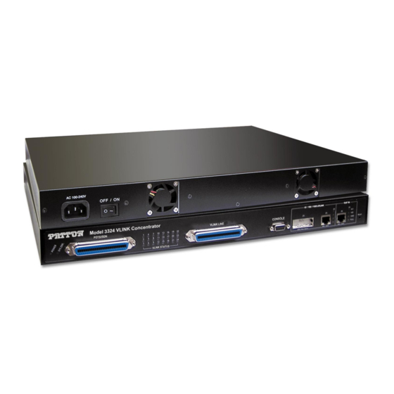
1 • General Information Hardware overview The Model 3324 combines networking and voice services by concentrating 24 x VDSL (Network) and 24 x POTS/ISDN ports for transport over a single phone grade twisted pair in a single 1U managed chassis. The 3324 (see figure 2... -
Page 16: Ethernet Uplink
Model 3324 User Guide Figure 3. Model 3324 rear panel power input connector Ethernet uplink The Model 3324 includes two Ethernet uplink ports. Uplink connections can be made either through the Ethernet GBIC (fiber connection) or via RJ-45 (copper connection) Also included are: •... -
Page 17: Vdsl Ports
Signal-to-noise ratio (SNR) for checking wiring quality and cross talk RS-232 control port The RS-232 port provides for initial configuration of the Model 3324. The RS-232 port supports: • Asynchronous data rate of 9600kbps, 8 data bits, no parity, 1 stop bit, flow control none. -
Page 18: Approvals
FD: Steady yellow if working at full-duplex, OFF if working at half-duplex • LINK: Steady green when the Model 3324 and CP has established a link, OFF when link is down Approvals The Model 3324 has achieved the following approvals and certifications: •... -
Page 19: Hardware Installation
Chapter 2 Hardware installation Chapter contents Introduction ................................20 Unpacking the Model 3324...........................20 Model 3324 chassis installation ..........................20 Cable installation..............................21 Installing the power cables—AC power supply ....................21 Connecting the Ethernet uplink ports ......................21 Cascading configuration ..........................22 Optional GBIC Ethernet uplink slot .......................24... -
Page 20: Introduction
Do not block the Model 3324 cooling fans. 2. If you are installing the Model 3324 in a 19-inch rack, go to step 3. Otherwise, place the Model 3324 at the desired location, then go to “Cable installation”... -
Page 21: Cable Installation
Model 3324 User Guide 2 • Hardware installation 3. Install the rack mounting ears onto the Model 3324 using the mounting hardware provided. 4. Place the Model 3324 at the desired position in the rack. 5. Secure the Model 3324 in position with the mounting screws. -
Page 22: Cascading Configuration
2 • Hardware installation Model 3324 User Guide Figure 4. Cascading configuration Cascading configuration When cascading more than two Model 3324s (see figure 4), the default settings are set to full duplex, and 1000 Mbps via the daisy-chain port. The maximum number of Model 3324s that can be cascaded is four units. If more than four units must be cascaded, an Ethernet switch will be required (see configuration example shown... - Page 23 Model 3324 User Guide 2 • Hardware installation Figure 5. Cascade configuration using Ethernet switch Cable installation...
-
Page 24: Optional Gbic Ethernet Uplink Slot
Model 3324 User Guide Optional GBIC Ethernet uplink slot The Model 3324 supports the use of one GBIC interface auto-link function. Normal Ethernet uplink port sta- tus default is copper (RJ-45), but you can use the hot-swap capability—modules can be exchanged without turning off power—of the Model 3324 to quickly change the uplink media to fiber. -
Page 25: Connecting The Pots/Isdn Ports
Connecting the POTS/ISDN Ports The remote (customer premise) VDSL modems will receive there POTS/ISDN connections from the Model 3324 via the VDSL twisted pair. The POTS/ISDN services from a PBX are connected into the 3324 via a RJ- 21X cable. Consult Appendix B, “Cabling”... -
Page 26: Completing The Hardware Installation
Failure to do so could result in equipment damage. 1. Verify that the AC power cord used with your 3324 is compatible with local standards. If it is not, refer to Chapter 6, “Contacting Patton for assistance”... -
Page 27: Configuring The 3324 For Operation
Connecting the DB9-RJ45 adapter with the included cable ................30 Setting up the HyperTerminal (or similar program) session ................30 Set IP address ..............................33 Remote Network Management..........................35 Controlling the Model 3324 remotely through TELNET ................35 Controlling the Model 3324 remotely through SNMP ...................35 Port Status ..............................36 State ................................36 Link Status ..............................36... - Page 28 3 • Configuring the 3324 for operation Model 3324 User Guide Console Port Settings ............................41 Port Control Settings ............................42 State ................................42 Negotiation ...............................42 Speed ................................42 Link Watch Dog(LWD) function: ...................... 42 Procedure for Changing VDSL Ports Speed Settings: ................42 Rate Control .............................43...
-
Page 29: Introduction
LAN IP address, netmask, and gateway parameters. • “Using a Web browser to complete Model 3324 configuration” on page XX—describes the process to com- plete the software installation parameters—that is, to bring it on-line. The steps are: Setting the switch features... -
Page 30: Initial Configuration Through The Rs-232 Control Port
3 • Configuring the 3324 for operation Model 3324 User Guide The IP address of the default gateway The 3324 VDSL port number to which each customer premises equipment (CPE) VDSL modem will be connecting The data rate at which each CPE VDSL will be operating The final destination of the CPE's VDSL modem connection... - Page 31 Model 3324 User Guide 3 • Configuring the 3324 for operation Figure 8. Connect To window 3. On the Connect To window (see figure 8), set Connect using: to one of the options named Direct to ComX (where the X refers to the number identifying the RS-232 serial port on the PC). In the following proce- dure, Com1 will be the used as the port identifier.
- Page 32 9. Connect the male end of the Model 3324 power cable to the power outlet. 10. When the PC connects with the Model 3324, boot up information will display on your HyperTerminal connection window, followed by a login request window.
-
Page 33: Set Ip Address
Model 3324 User Guide 3 • Configuring the 3324 for operation Figure 11. Main Menu Set IP address 1. Do the following: 2. Choose Switch Static Configuration from the Main Menu screen (see figure 11). Figure 12. Switch Configuration menu 3. - Page 34 System Configuration page. Save 8. Choose item to exit System Configuration page. Previous Menu 9. Choose item to exit the 3324 Switch Configuration page and return to Main Menu. Main Menu Initial configuration through the RS-232 control port...
-
Page 35: Remote Network Management
IP domain same with VDSL SWITCH. Then use the default IP address to control this VDSL concentrator. Controlling the Model 3324 remotely through TELNET To enter Telnet, type the IP address of the Model 3324 to connect management system. And type user name and password. Default User Name: admin... -
Page 36: Port Status
SNR (Signal to Noise Ratio) The SNR is used to indicate the quality of the link. If the SNR value is greater than (>) 25, it means a good link has been established between the 3324 and CPE. Remote Network Management... -
Page 37: Speed Status
Model 3324 User Guide 3 • Configuring the 3324 for operation Speed Status • Config: Displays user configured port settings 1-24 at 5/10/15 Mbps and port 25/26 at 10/100/1000 Mbps • Actual: Displays the actual line rate the individual links have achieved Duplex Status •... -
Page 38: Port Statistics
This page provides and administrator a quick overview on every ports LAN statistics. These statistics can be rest at any time by double clicking the reset icon at the bottom of the menu screen. Administrator Most of the management functions of the 3324 can be found in this menu. Management functions include: • IP address •... -
Page 39: Ip Address Configuration
Displays write to default EEPROM value table version Advanced Switch Settings Mac Address Age-out Time Enter the number of second that in inactive MAC address remains in the 3324’s address table. The valid range is between 300–765 seconds. (Default 300 seconds). Administrator... -
Page 40: Max Bridge Transit Delay Bound Control
Select the preference given to packets in the 3324’s high-priority queue. These options represent the number of high priority packets that will be sent before one low priority packet is sent. For example, 5 High/2 Low means that the 3324 will send the 5 high priority packets before sending the 2 low priority packets. Administrator... -
Page 41: Enable Delay Bound
Limits the low priority packets queuing time in switch. The Default Max Delay Time is 255ms. If the low pri- ority packets stay in 3324 exceeds Max Delay Time, it will be sent. The valid range is 1~255 ms. Note Make sure that the “Max Bridge Transit Delay Bound Control”... -
Page 42: Port Control Settings
• Enable (ON) • Disable (OFF) Negotiation The administrator can set the auto negotiation mode for the CPE devices through the 3324. The three choices are: • Auto • Nway (TM) (specify the speed/duplex on this port and enable auto-negotiation) •... -
Page 43: Rate Control
Port 1-24 on the Model 3324 supports port-by-port ingress and egress rate control. For example, assume Port 1 is 10Mbps, users can set it’s effective egress rate is 1Mbps, ingress rate is 500 kbps. The Model 3324 will be performing flow control or back-pressure to confine the ingress rate to meet the specified rate. -
Page 44: Flow Control
IEEE802.3ad. System Priority This is the value used to identify the active LACP. The 3324/Switch with the lowest value has the highest pri- ority and is selected as the active LACP. There are six steps to activate LACP. - Page 45 Model 3324 User Guide 3 • Configuring the 3324 for operation When you are setting the LACP aggregator, you will see one of the following screens below. This page is when no group is active. LACP is not working. This page shows a Static Trunking group. LACP is working.
-
Page 46: State Activity
Filter Database IGMP Snooping The Model 3324 supports IP multicast. IP manages multicast traffic by using switches, routers, and hosts that support IGMP (Internet Group Management Protocol). Enabling IGMP allows the ports to detect IGMP queries and report packets and manage IP multicast traffic through the switch. IGMP can be enabled through the web management’s switch settings advanced page. -
Page 47: Static Mac Address
Model 3324 User Guide 3 • Configuring the 3324 for operation IP manages multicast traffic by using switches, routers, and hosts that support IGMP. Enabling IGMP allows the ports to detect IGMP queries and report packets and manage IP multicast traffic through the switch. -
Page 48: Mac Filtering
MAC address. 3. Click the button. 4. Choose the MAC address that you want to delete and then click the button. Delete VLAN Configurations The Model 3324 supports both port-based and 802.1Q (tagged-based) VLAN, through the web management page. Administrator... -
Page 49: Support Port-Based Vlan
If you change the VLAN Operation Modem from disabled to enabled, you must wait 50 seconds. Every time you reboot the Pat- ton Model 3324 you will have to change the VLAN mode to a valid value. Support Port-based VLAN Packets can only be transmitted and received among members of the same VLAN group. -
Page 50: Tagged-Based Vlan
3 • Configuring the 3324 for operation Model 3324 User Guide Note If the trunk group exists, you can see it (ex. TRK1,TRK2…..) in select menu of ports, and you can configure it is the member of the VLAN or not. - Page 51 Model 3324 User Guide 3 • Configuring the 3324 for operation VLAN is enabled, all ports on the Model 3324 will belong to the default VLAN (VID 1). The default VLAN cannot be deleted. GVRP allows automatic VLAN configuration between the switch and nodes. If the Model 3324 is connected to a device with GVRP enabled, you can send a GVRP request using the VID of a VLAN defined on the Pat-...
- Page 52 6. Choose the protocol type. 7. From the available ports box on the left, select which ports to add to the 3324 and click “Add ”. If the trunk groups exist, you can see it in here (ex:TRK1,TRK2…). If you want to configure the TRK as a member of the VLAN you can do it through this screen.
-
Page 53: Port Vid
VLAN but that don’t support tagging. Each port of the Model 3324 allows the user to set one PVID, the range is 1~255 and the default PVID is 1. The PVID must as same as the VLAN ID that the port belong to VLAN group, or the untagged traffic will be dropped. - Page 54 Model 3324 User Guide menu, then select enable STP. It is recommended that you enable STP on your Model 3324 to ensure a single active path on your network. Additionally, you can view STP information about the Root Bridge by clicking on Root Bridge Information (see figure...
-
Page 55: Port Sniffer
Model 3324 User Guide 3 • Configuring the 3324 for operation • Forward Delay Time: Forward Delay Time is the number of seconds a port waits before changing from its STP learning and listening states to the forwarding state. The valid range is from 4-30. -
Page 56: Snmp Settings
Use this page to define management stations, trap managers, and to enter SNMP community strings. Users can also define a name, location, and contact person for the 3324. Fill in the system options data, then click Apply to update the changes on this page. -
Page 57: Security Manager
3 • Configuring the 3324 for operation Trap Manager is a management station that receives traps (system alerts generated by the 3324). If no trap manager is defined, no traps are issued. Create a trap manager by entering the IP address of the station and a community string. -
Page 58: Per Port Configuration
3 • Configuring the 3324 for operation Model 3324 User Guide • Accounting Port: The UDP port number used by the authentication server to retrieve accounting informa- tion. • Shared Key: A key shared between this switch and authentication server. -
Page 59: Using Tftp
Use this page to set the TFTP server address. You can restore the EEPROM values from here. It is important to first put the image back in the TFTP server, then the Model 3324 will download the original flash image. -
Page 60: Tftp Backup Configuration
EEPROM value has been saved, go to the TFTP restore configuration page to restore the EEPROM value. Resetting the Model 3324 Reset the Patton Model 3324 to default configuration, default value as below. Rebooting the Model 3324 Reboot the Patton Model 3324 in software reset. -
Page 61: Applications
Chapter 4 Applications Chapter contents MxU multi-service delivery............................62 High bandwidth backbone ............................63... -
Page 62: Mxu Multi-Service Delivery
Model 3324 VDSL Carrier-Class Aggregator Configuration Guide MxU multi-service delivery The Model 3324 provides a high speed, 5/10/15Mbps transmission over existing home telephone wiring over a single Internet account to provide simultaneous independent Internet access to multiple users. Either ISDN or POTS Telephone systems can be used. -
Page 63: High Bandwidth Backbone
Model 3324 VDSL Carrier-Class Aggregator Configuration Guide 4 • Applications High bandwidth backbone The Model 3324 provides 10/100/1000Mbps auto sensing Uplinks for bandwidth intensive applications. Figure 27. Application for VOD and Video conference High bandwidth backbone... - Page 64 4 • Applications Model 3324 VDSL Carrier-Class Aggregator Configuration Guide 1068DV 3324 Figure 28. Broadband access applications utilizing Model 3324 High bandwidth backbone...
-
Page 65: Troubleshooting
Chapter 5 Troubleshooting Chapter contents Diagnosing VDSL indicators ..........................66 System Diagnostics ..............................66 Power and Cooling Problems ..........................66 Installation ................................67 Transmission Mode ............................67 Cabling ................................67 Physical Configuration ............................67 System Integrity ..............................67 CPE (Customer Premise/Remote) Side Starts Link Watch Dog ................67... -
Page 66: Diagnosing Vdsl Indicators
Model 3324 VDSL Carrier-Class Aggregator Configuration Guide Diagnosing VDSL indicators The Model 3324 is easily monitored through its comprehensive panel indicators. These indicators assist the network manager in identifying problems the Model 3324 may encounter. This section describes the common problems you may encounter and possible solutions. -
Page 67: Installation
If the CPE side (VDSL Modem) is on power standby for an excess of 20 minutes without connecting to the Model 3324, the link has failed. The users must power cycle the CPE once to clear and the CPE should recon- nect to the Model 3324. - Page 68 5 • Troubleshooting Model 3324 VDSL Carrier-Class Aggregator Configuration Guide CPE (Customer Premise/Remote) Side Starts Link Watch Dog...
-
Page 69: Contacting Patton For Assistance
Chapter 6 Contacting Patton for assistance Chapter contents Introduction ................................70 Contact information..............................70 Warranty Service and Returned Merchandise Authorizations (RMAs)..............70 Warranty coverage ............................70 Out-of-warranty service ..........................70 Returns for credit ............................70 Return for credit policy ..........................71 RMA numbers ..............................71 Shipping instructions ..........................71... -
Page 70: Introduction
6 • Contacting Patton for assistance Model 3324 VDSL Carrier-Class Aggregator Configuration Guide Introduction This chapter contains the following information: • “Contact information”—describes how to contact PATTON technical support for assistance. • “Warranty Service and Returned Merchandise Authorizations (RMAs)”—contains information about the RAS warranty and obtaining a return merchandise authorization (RMA). -
Page 71: Return For Credit Policy
Model 3324 VDSL Carrier-Class Aggregator Configuration Guide 6 • Contacting Patton for assistance Return for credit policy • Less than 30 days: No Charge. Your credit will be issued upon receipt and inspection of the equipment. • 30 to 60 days: We will add a 20% restocking charge (crediting your account with 80% of the purchase price). - Page 72 6 • Contacting Patton for assistance Model 3324 VDSL Carrier-Class Aggregator Configuration Guide Warranty Service and Returned Merchandise Authorizations (RMAs)
- Page 73 Appendix A Specifications Chapter contents VDSL line interface ...............................74 POTS-ISDN interface............................74 Modulation ................................74 Frequency range ..............................74 Transmission .................................74 Management .................................74 Ethernet standards ..............................74 Management standards ............................74 LED indicators ..............................74 Power supply .................................74 Compliance ................................74 Environment .................................74 Operating temperature ............................74 Humidity ................................75 Dimensions ................................75...
-
Page 74: A Specifications
A • Specifications Model 3324 VDSL Carrier-Class Aggregator Configuration Guide... -
Page 75: Vdsl Line Interface
Model 3324 VDSL Carrier-Class Aggregator Configuration Guide A • Specifications VDSL line interface 24 ports presented on one RJ-21 POTS-ISDN interface 24 ports presented on one RJ-21 Modulation QAM (Quadrature Amplitude Modulation) Frequency range • VDSL: 1–8 MHz • POTS/ISDN: 0–120 kHz... -
Page 76: Humidity
A • Specifications Model 3324 VDSL Carrier-Class Aggregator Configuration Guide Humidity 10–90% non-condensing Dimensions 2.0H x 17.5W x 16.5L inch (5.08H x 44.45W x 41.91L cm) Weight 12.5 lbs (5.66 kg) Dimensions... -
Page 77: Cabling
Appendix B Cabling Chapter contents Introduction ................................78... -
Page 78: Introduction
B • Cabling Model 3324 VDSL Carrier-Class Aggregator Configuration Guide Introduction RJ-21 Telco ports distribution Table 3. RJ-21 Pin and VDSL port contrast list VDSL 50 Pin RJ-21 Cable Connector List Cable Characteristic = 24 AWG twist wire VDSL Port No. - Page 79 Model 3324 VDSL Carrier-Class Aggregator Configuration Guide B • Cabling Figure 29. RJ-21 Cable Drawing (1500 cm Male to Male) Introduction...
- Page 80 B • Cabling Model 3324 VDSL Carrier-Class Aggregator Configuration Guide Introduction...
-
Page 81: Vdsl Spectrum
Appendix C VDSL Spectrum Chapter contents Introduction ................................82... -
Page 82: Introduction
C • VDSL Spectrum Model 3324 VDSL Carrier-Class Aggregator Configuration Guide Introduction Spectrum allocation VDSL Technology – Requirements & Definitions Spectral Allocation • Co-exists with legacy Voice and ISDN services • Co-exists with other xDSL technologies • Programmable notch filter to avoid Radio Frequency Interference... -
Page 83: Example Of Vlan Setting
Appendix D Example of VLAN Setting Chapter contents Introduction ................................84... -
Page 84: Introduction
D • Example of VLAN Setting Model 3324 VDSL Carrier-Class Aggregator Configuration Guide Introduction Web management -> Administrator -> Switch settings -> Advanced: protocol setting -> VLAN Operation Mode: Select “Port_Based” Web management -> Administrator -> Switch settings -> Vlan Configuration:... - Page 85 Model 3324 VDSL Carrier-Class Aggregator Configuration Guide D • Example of VLAN Setting Add VLAN Group 1, member: port 1 and port 9 Introduction...
Need help?
Do you have a question about the 3324 and is the answer not in the manual?
Questions and answers