Patton electronics 3096RC Getting Started Manual
G.shdsl tdm-digital access concentrator (t-dac)
Hide thumbs
Also See for 3096RC:
- Specifications (2 pages) ,
- Administrator's reference manual (315 pages)
Table of Contents
Advertisement
Quick Links
Advertisement
Table of Contents

Related Manuals for Patton electronics 3096RC


Summary of Contents for Patton electronics 3096RC
- Page 1 Model 3096RC G.SHDSL TDM-Digital Access Concentrator (T-DAC) Getting Started Guide Sales Office: +1 (301) 975-1000 Technical Support: +1 (301) 975-1007 E-mail: support@patton.com WWW: www.patton.com Document Number: 11011U1-001 Rev. D Part Number: 07MD3096RC-GS Revised: June 29, 2005...
- Page 2 The software described in this document is furnished under a license and may be used or copied only in accordance with the terms of such license. Patton Electronics warrants all Model 3096RC components to be free from defects, and will—at our option—repair or replace the product should it fail within one year from the first date of the shipment.
-
Page 3: Summary Table Of Contents
Summary Table of Contents Introduction ..............................16 Hardware installation............................ 24 Configuring the T-DAC for operation ......................35 Operation and shutdown ..........................69 Troubleshooting and maintenance ........................ 71 Contacting Patton for assistance ........................86 Network Ports (RJ-21X) connector pin-out ....................89 WAN Network Module connector pinout .................... -
Page 4: Table Of Contents
Precautions ................................14 Typographical conventions used in this document....................14 General conventions ............................14 Mouse conventions ............................15 Introduction ..............................16 Model 3096RC G.SHDSL T-DAC overview ......................17 Hardware overview ..............................18 ................................18 ................................19 RS-232 control port ............................19 Power system ..............................19 Central processing unit ...........................19... - Page 5 Configuring the DS0 mapping ........................48 Examples for configuring static connections....................49 Activating the G.SHDSL ports ........................55 Configuring Patton G.SHDSL CPE device remotely via the Model 3096RC ..........57 Configuring line settings and signaling for E1 ....................58 Accessing the Line Interface Settings ......................58 Configuring the E1 line interface settings ......................59...
- Page 6 Model 3096RC T-DAC Getting Started Guide Table of Contents Remote serial loop (RemSerLoop) ......................76 Remote Ethernet loop (RemEtherLoop) ....................77 Line loop (LineLoop) ..........................78 T1/E1 port test modes ............................79 DSX1 payload loop (dsx1PayloadLoop) ....................79 DSX1 line loop (dsxLineLoop) ........................79 Periodic maintenance ............................80...
-
Page 7: List Of Figures
Model 3096RC network and configuration ports ........ - Page 8 3096RC Configuration Menu home page ........
-
Page 9: List Of Tables
List of Tables General conventions ..............14 Mouse conventions . -
Page 10: Compliance Information
The Model 3096RC has been tested and found to comply with the limits for a Class A computing device in accordance with the specifications in Subpart B of Part 15 of FCC rules, which are designed to pro- vide reasonable protection from such interference in a commercial installation. -
Page 11: Industry Canada Notice
Model 3096RC T-DAC Getting Started Guide Compliance Information T /4 & T /4 & T /4 & T /4 & & Install clamp-on ferrite on DSL cable, within 12 inches & (30 cm) of DSL connector & M IN &... -
Page 12: Ce Notice
Model 3096RC T-DAC Getting Started Guide Compliance Information A plug and jack used to connect this equipment to the premises wiring and telephone network must comply with the applicable FCC Part 68 rules and requirements adopted by the ACTA. This equipment uses a Universal Service Order Code (USOC) jack: RJ-11C. -
Page 13: About This Guide
About this guide This guide describes installing and configuring a Patton Electronics Model 3096 TDM-Digital Access Concen- trator (T-DAC). By the time you are finished with this guide, your T-DAC will be connected to the remote DSL modems and transferring data. The instructions in this guide are based on the following assumptions: •... -
Page 14: Precautions
Model 3096RC T-DAC Getting Started Guide About this guide Precautions Notes and cautions, which have the following meanings, are used throughout this guide to help you become aware of potential T-DAC problems. Warnings relate to personal injury issues, and Cautions refer to potential property damage. -
Page 15: Mouse Conventions
Model 3096RC T-DAC Getting Started Guide About this guide Table 1. General conventions (Continued) Convention Meaning Indicates the names of command buttons that execute an action. Garamond bold type < > Angle brackets indicate function and keyboard keys, such as <SHIFT>, <CTRL>, <C>, and so on. -
Page 16: Introduction
Chapter 1 Introduction Chapter contents Model 3096RC G.SHDSL T-DAC overview ......................17 Hardware overview ..............................18 ................................18 ................................19 RS-232 control port ............................19 Power system ..............................19 Central processing unit ...........................19 G.SHDSL ports ..............................19 System timing ..............................19 Temperature ..............................20 Altitude ................................20 Humidity ................................20 Physical dimensions ............................20... -
Page 17: Model 3096Rc G.shdsl T-Dac Overview
(via T1/E1 Frame Relay/PPP links) or out-of-band from a web browser by means of SNMP/HTTP-based management screens. The Model 3096RC connects 16 G.SHDSL remote NTUs or modems at data-rates up to 4.6 Mbps to digital (ATM/FR/DDN/IP) networks, thus permitting multi-service access to CLECs, ISPs, and PTTs. -
Page 18: Hardware Overview
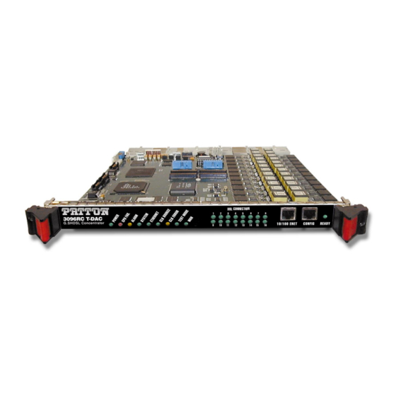
Figure 3. Model 3096RC T-DAC features The 3096RC includes four, eight, twelve, or sixteen WAN uplink ports selectable for T1 or E1 operation. The WAN uplink ports may be connected to ATM/FR/DDN/ IP network backbones and are accessible via the 68- pin SCSI connector. -
Page 19: Lan
Hardware flow control (RTS and CTS) Power system The 3096RC obtains power from the CPCI chassis via PCMG 2.11 47-pin power connectors on the front and rear blade. Total power consumption is a maximum of 43 Watts, provided by modular power supplies installed in the CPCI chassis. -
Page 20: Temperature
Model 3096RC T-DAC Getting Started Guide 1 • Introduction The system timing is configured through the NMS. Temperature Operating range: 32–104˚F (0–40˚C) Altitude Maximum operating altitude: 15,000 feet (4,752 meters) Humidity 5 to 95% relative humidity (RH), non-condensing Physical dimensions •... -
Page 21: Led Display
POWER Green On solid Power is being applied. No action recommended. Flashing The 3096RC has detected a power failure on a power bus. No input power is being applied. CPU FAIL On solid CPU is unable to load the software from FLASH to RAM for operation. - Page 22 3096RC. b. Revisions A and B of the Model 3096RC are configured with a single DSL LED on the front panel. When lit, the DSL LED indicates that one or more G.SHDSL ports has successfully established a link and no G.SHDSL ports have errors;...
-
Page 23: Approvals
Model 3096RC T-DAC Getting Started Guide 1 • Introduction Approvals The Model 3096RC T-DAC has achieved the following approvals and certifications: • Safety UL 60950 Industry Canada CSA C22.2 No. 60950 • RTTE Directive (CE Mark) EMC Directive 89/336/EEC Low Voltage Directive 73/23/EEC (EN 60950) -
Page 24: Hardware Installation
Chapter 2 Hardware installation Chapter contents Introduction ................................25 Unpacking the Model 3096RC T-DAC ........................25 T-DAC blades installation .............................25 Cable installation..............................27 Connecting the Ethernet ports ........................27 Connecting the 10/100Base-T Ethernet port to an Ethernet switch or hub ..........27 Connecting the 10/100Base-T Ethernet port to an Ethernet-capable workstation or PC .........28... -
Page 25: Introduction
Model 3096RC T-DAC Getting Started Guide 2 • Hardware installation Introduction This chapter contains the following procedures for installing the Model 3096RC T-DAC: Note Before installing the T-DAC, you will need to obtain the line type and encoding of the T1/E1 line from your local telephone company (Telco). -
Page 26: Alignment/Esd Pin And Card Handle
Model 3096RC T-DAC Getting Started Guide 2 • Hardware installation Note The T-DAC should be installed as close as possible to the termination jack provided by the Telco. The location should be well ventilated. Do not block the rack chassis’ cooling vents. -
Page 27: Cable Installation
READY Handle Figure 6. Model 3096RC network and configuration ports Connecting the 10/100Base-T Ethernet port to an Ethernet switch or hub The 10/100Base-T Ethernet port (see figure 5) is designed to connect to an Ethernet switch or hub. The Ethernet RJ-45 pin and signal definitions for the T-DAC or for a NIC card in a workstation/PC are shown... -
Page 28: Connecting The 10/100Base-T Ethernet Port To An Ethernet-Capable Workstation Or Pc
Model 3096RC T-DAC Getting Started Guide 2 • Hardware installation Figure 7. Ethernet RJ-45 pin and signal definitions for T-DAC Connecting the 10/100Base-T Ethernet port to an Ethernet-capable workstation or PC The 10/100Base-T Ethernet port can connect to a single Ethernet-capable workstation or PC by means of a cross over cable. -
Page 29: Connecting To The T1/E1 Wan Ports
An active T1/E1 is not necessary to configure the T-DAC. However, an active T1/E1 connection is required when mapping G.SHDSL modems to specific time slots in the T1/E1 ports or even for mapping WAN time slots to other WAN time slots. The factory-set default configuration of the Model 3096RC has the T1/E1 ports disabled. Note... -
Page 30: Wan Cable's 68 Non-Terminated Twisted-Pairs
Model 3096RC T-DAC Getting Started Guide 2 • Hardware installation 2. The other end of the cable has 68 non-terminated twisted-pairs for connection to a punch-down block (see table 4). Select the twisted pairs for the WAN ports that will be activated and terminate them on the punch-down block. -
Page 31: Connecting The G.shdsl Ports
50-pin TELCO Male Figure 12. RJ-21X connector 1. Connect the RJ-21X connector of the cable into the 50-pin RJ-21X receptacle on the rear of the 3096RC. 2. The other end of the cable has 25 non-terminated twisted-pairs for connection to punch-down blocks. -
Page 32: Connecting The Bits Clock
3. Select and attach the appropriate twisted pair from each remote (CPE) G.SHDSL modem on punch-down blocks for connection to the chosen G.SHDSL port in the 3096RC. Connecting the BITS clock The ForeFront system can accept and synchronize with an external reference clock signal provided by a build- ing integrated timing system (BITS) residing at the installation site. -
Page 33: Ext Clock Connector Location
Model 3096RC T-DAC Getting Started Guide 2 • Hardware installation Note To synchronize the ForeFront system with a BITS clock, you must connect the site BITS clock system to the EXT CLOCK connector located on the rear-panel of the T-DAC WAN Access Module rear card (see figure... -
Page 34: Completing The Hardware Installation
Power is delivered from the CPCI chassis backplane through the 47-pin PICMG 2.11 power connectors on the 3096RC blades. Upon insertion into the CPCI chassis, the Model 3096RC immediately powers up and begins its boot cycle. During the boot cycle the following should occur: 1. -
Page 35: Configuring The T-Dac For Operation
Configuring the DS0 mapping ........................48 Examples for configuring static connections....................49 Activating the G.SHDSL ports ........................55 Configuring Patton G.SHDSL CPE device remotely via the Model 3096RC ..........57 Configuring line settings and signaling for E1 ....................58 Accessing the Line Interface Settings ......................58 Configuring the E1 line interface settings ......................59... -
Page 36: Configuring The T-Dac For Operation
Model 3096RC T-DAC Getting Started Guide 3 • Configuring the T-DAC for operation Introduction This chapter contains the following procedures that describe configuring the Model 3096RC T-DAC for operation: • “Configuration prerequisites”—lists the items you need to have on hand before configuring the T-DAC. -
Page 37: Initial Configuration Through The Rs-232 Control Port
Connecting the DB9-RJ45 adapter with the included cable Do the following: 1. Find the DB9-RJ45 adapter for your PC and RJ-45-to-RJ45 cable shipped with your 3096RC T-DAC. 2. Connect the DB9-RJ45 adapter to your PC’s RS-232 serial port. 3. Connect the RJ45-RJ45 cable between the adapter which you installed in step 1 and the RS-232 Config port on the front of the Model 3096RC (figure... -
Page 38: Setting Up The Hyperterminal (Or Similar Program) Session
1. At your PC, find the file HYPERTRM.EXE. Open a HyperTerminal session by double-clicking on the file name. Figure 15. Connection Description window 2. Type a connection name (e.g., 3096RC Config), select an icon, then click (figure 16). Figure 16. Connect To window 3. -
Page 39: Com1 Properties Window
Model 3096RC T-DAC Getting Started Guide 3 • Configuring the T-DAC for operation 6. Configure your COM port settings as shown in figure 17, then click Figure 17. COM1 Properties window 7. Click on the menu, then select Properties. File 8. -
Page 40: Login Window
Model 3096RC T-DAC Getting Started Guide 3 • Configuring the T-DAC for operation 9. Connect the male end of the 3096RC T-DAC’ power cables to the power outlets. 10. Boot up information will display on your HyperTerminal connection window, eventually followed by a login request window (see figure... -
Page 41: Using A Browser To Complete Model 3096Rc Configuration
(store Config(1)) to save the changes you have just made to the con- figuration. This completes the initial configuration of the Model 3096RC. The next steps in configuration will be done using your Web browser connected via Ethernet to the 3096RC. -
Page 42: Home
Configuration Menu pane (see figure 22 on page 43). The contains the links to the various Model 3096RC Configuration/information subsystems, while in the pane, you can view status and other information or make Configuration Menu changes to the system configuration. Unlike the pane, which appears the same no matter Configuration/information... -
Page 43: Home Page Window Panes
DRAM memory to FLASH memory. Once the configuration is saved into FLASH memory, the configuration will not be lost even if the power is cycled on the 3096RC. Initially, changes made to the 3096RC configuration are stored in volatile DRAM, enabling the user to set the box up with a working... -
Page 44: Configuring The Default Gateway
The default gateway IP address, if defined, is used solely for managing the 3096RC remotely via the Ethernet port. The 3096RC does not transmit or receive user data nor any other traffic via the default gateway IP address or the Ethernet port. -
Page 45: Ip Routing Information Page
24). Figure 24. IP Routing Information Page 3. The existing route you see in the table is the LAN IP address you assigned to the 3096RC during initial configuration through the RS-232 control port, earlier in this chapter. 4. To enter the default gateway, use the first . -
Page 46: Configuring The System Clocking Parameters
Example 1 Your 3096RC is the only blade in the chassis and must be configured as the system clocking master. This example assumes you will use WAN port #1 as the main reference and WAN port #2 as the fallback reference To define... - Page 47 Example 2 Another card such as the Patton Model 6511 is the clocking master and your 3096RC is a slave. This example assumes you will use the system clock as the main reference and WAN port #1 as the fallback reference. To define the clocking source, do the following:...
-
Page 48: Configuring The Ds0 Mapping
G.SHDSL modem may be at the end of a T1 or E1 link, or another G.SHDSL port. Each G.SHDSL modem inside the 3096RC T-DAC is configured by selecting the number of DS0 time slots, each time slot being 64 kbps. You may choose to map from 1 to 31 DS0 time slots in the G.SHDSL modem. The most common destination for the G.SHDSL modems will be at the remote end of a T1/E1 WAN link. -
Page 49: Examples For Configuring Static Connections
T1/E1 WAN line or gsdsl(4)for a G.SHDSL modem. Device Number: Defines which WAN or G.SHDSL port number on the 3096RC you are map- ping. For example, to map a connection for G.SHDSL port 3 (i.e. G.SHDSL modem #3) you would select port3(3) Device Slots. - Page 50 At this point the DS0 channel mapping is completed. Now is time to configure the DTE data rate of the G.SHDSL modem, refer to sec- tion “Activating the G.SHDSL ports” on page 55. Using a browser to complete Model 3096RC configuration...
- Page 51 Model 3096RC T-DAC Getting Started Guide 3 • Configuring the T-DAC for operation 8. On the 3096RC Configuration Menu, click the DSL hyperlink to open the G.SHDSL Port Configuration page (figure 30). Using your mnemonic naming convention scheme, enter a name for this connection in the Circuit ID field to the right of Port #3 (optional).
-
Page 52: G.shdsl Port 3 Details Page
11. Near the bottom of the pane, change Payload Rate to r1984(31) and click the button. You will Submit automatically return to the page. G.SHDSL Port Information You have completed the DS0 mapping configuration for example 1. Using a browser to complete Model 3096RC configuration... - Page 53 At this point the DS0 channel mapping is completed. Now we need to configure the DTE data rate of the G.SHDSL modem. 8. Click the DSL hyperlink on the 3096RC Configuration Menu. 9. On the Configuration/information pane, click on the number 15 under the column titled Port # to open page.
- Page 54 20. Under Dev Num B, bottom window, select port1(1). 21. Under Dev Slots B, bottom window, enter 1. 22. Click on Submit Query. 23. You have completed the configuration for example 4. Using a browser to complete Model 3096RC configuration...
-
Page 55: Activating The G.shdsl Ports
3 • Configuring the T-DAC for operation Activating the G.SHDSL ports Do the following to activate a G.SHDSL port: 1. On the 3096RC Configuration Menu, click the DSL hyperlink to display the G.SHDSL Port Configura- tion page (see figure 33). (Optional: Using your mnemonic naming convention scheme, enter a name for this connection in the “Circuit ID”... -
Page 56: G.shdsl Port # Details Page
Figure 36. G.SHDSL Port # Details page You have now completed the procedure to activate one G.SHDSL port. To activate additional G.SHDSL ports, repeat the above procedure for each port you wish to activate. Using a browser to complete Model 3096RC configuration... -
Page 57: Configuring Patton G.shdsl Cpe Device Remotely Via The Model 3096Rc
Once a G.SHDSL link is established between the 3096RC port and a Patton Customer Premise Equipment (CPE) G.SHDSL device, (such as the Model 3086 G.SHDSL IAD) you may use the 3096RC Web Manage- ment pages to remotely configure DSL port parameters on the CPE device. The following DSL port parame- ters may be configured remotely:... -
Page 58: Configuring Line Settings And Signaling For E1
G.SHDSL Port # Details page. You have now completed the procedure to remotely configure one Patton G.SHDSL CPE device via the Model 3096RC. To activate additional Patton CPE devices, repeat the above procedure for each device you wish to configure. -
Page 59: Configuring The E1 Line Interface Settings
Figure 39. WAN Circuit Configuration page, Line Interface Settings Configuring the E1 line interface settings 1. From the Line Type pull-down menu (see figure 40) select dsx1E1(4) or dsx1E1-CRC(5). Figure 40. Line Type pull-down menu Using a browser to complete Model 3096RC configuration... -
Page 60: Line Coding Pull-Down Menu With Dsx1Hdb3(3) Selected
43) for that T1/E1 link. Figure 43. E1 ALARMS PRESENT indicator After you connect the E1 line to the WAN port on the rear of the Model 3096RC these alarms should disappear. Using a browser to complete Model 3096RC configuration... -
Page 61: Configuring Line Settings And Signaling For T1
3 • Configuring the T-DAC for operation Configuring line settings and signaling for T1 Accessing the Line Interface Settings 1. On the 3096RC Configuration Menu, click the T1/E1 Link hyperlink to open the T1/E1 LINK ACTIV- ITY OVERVIEW page (see figure 44). -
Page 62: Configuring The T1 Line Settings
1. From the Line Type pull-down menu (see figure 47) select either: – dsx1ESF(2) - indicates Extended SuperFrame DS1 – dsx1D4 - indicates AT&T D4 format DS1 Figure 47. Line Type pull-down menu with dsx1ESF(2) selected Using a browser to complete Model 3096RC configuration... -
Page 63: Line Coding Pull-Down Menu With Dsx1B8Zs(2) Selected
Figure 50. T1 ALARMS PRESENT indicator on T1/E1 LINK ACTIVITY page After you connect the E1 line to the WAN port on the rear of the Model 3096RC, these alarms should disappear. Using a browser to complete Model 3096RC configuration... -
Page 64: Saving Your Configuration
At this point you have completed the basic configuration of your T-DAC for operation. To save your configu- ration settings in non-volatile RAM, do the following: 1. On the Configuration Menu click the Select HOME hyperlink to open the 3096RC Configuration Menu home page (see figure... - Page 65 Model 3096RC T-DAC Getting Started Guide 3 • Configuring the T-DAC for operation Note The parameters that will be exported are the power-up settings as they are stored in flash memory and may not be the current operating parameters. To ensure that you export the most current parameters, go to HOME, then under Immediate Actions, click on the Record Current Configuration button.
-
Page 66: Backing Up The Configuration Store In Flash Memory
Model 3096RC T-DAC Getting Started Guide 3 • Configuring the T-DAC for operation Backing up the configuration store in flash memory 1. To make a back-up copy of the configuration file currently stored in your T-DAC’s flash memory: – On the Import/Export page (see figure... -
Page 67: Completing The Installation
71. 3. Verify that the WAN LED illuminates, indicating that the Model 3096RC is synchronized with the T1/E1 signal. 4. After 5 seconds, verify the WAN A Error LED begins flashing, indicating that the T-DAC is satisfied with the quality of the T1/E1 signal. - Page 68 Congratulations! Your T-DAC is now installed. If you require further information about configuring your T- DAC settings, refer to the DSL T-DAC Administrator’s Reference Guide included on your Model 3096RC CD-ROM.
-
Page 69: Operation And Shutdown
Chapter 4 Operation and shutdown Chapter contents Introduction ................................70 Activating the Model 3096RC..........................70 De-activating the Model 3096RC..........................70... -
Page 70: Introduction
Be sure to wear an anti-static strap to prevent electrostatic damage to the blade. 1. Unlock the handles on the front of the 3096RC by pressing the red button on each handle. The button immediately activates the switch (turning it to an open position), while the button itself remains depressed. -
Page 71: Troubleshooting And Maintenance
DSX1 line loop (dsxLineLoop) ........................79 Periodic maintenance ............................80 Calibration ..............................80 Maintenance................................80 Replacing the Model 3096RC .........................80 Exporting the current Model 3096RC configuration ................80 Removing the defective Model 3096RC ....................83 Installing the replacement Model 3096RC ....................84 Importing a saved configuration ........................84 Completing the installation... -
Page 72: Introduction
POWER LED (green) is The 3096RC has detected a power failure on a power bus. There may be a problem with the CPCI chassis power system which feeds the Model 3096RC such as a failed power sup- flashing ply module in the chassis. -
Page 73: Fault Analysis
5 • Troubleshooting and maintenance Fault analysis The following procedures outline steps you should follow when troubleshooting a Model 3096RC malfunction. 1. If possible, talk to the person who filed the trouble complaint and determine the operational symptoms. Record the symptoms on the appropriate trouble report form (include the front panel LED indications). - Page 74 The 3096RC is set as the slave, getting its clock from the H.110 Bus. No action recommended. CLK ERROR Front panel Yellow On solid Master Clock source has been lost and the 3096RC is using the secondary source for its clock. Flashing Master Clock source and the Secondary Clock source have been lost and the 3096RC is using its internal crystal for its clock.
-
Page 75: Basic G.shdsl And T1/E1 Test Modes
3096RC b. Revisions A and B of the Model 3096RC are configured with a single DSL LED on the front panel. When lit, the DSL LED indicates that one or more G.SHDSL ports has successfully established a link and no G.SHDSL ports have errors;... -
Page 76: Remote Serial Loop (Remserloop)
The remote serial loop, initiated from the 3096RC, will place a remote CPE (3086) in loopback mode. Under this condition, data sent by the 3096RC over the DSL link and destined to the serial port of a Model 3086 will be sent back to the 3096RC (see figure... -
Page 77: Remote Ethernet Loop (Remetherloop)
The remote Ethernet loop, initiated from the 3096RC, will place a remote CPE (3086 or 3201) in loop mode. Under this condition, data sent by the 3096RC over the DSL link and destined to the Ethernet port of a Model 3086, or a Model 3201 CPE will be sent back to the 3096RC (see figure... -
Page 78: Line Loop (Lineloop)
Line loop (LineLoop) The line loop, initiated from the 3096RC, tests the DSL link between a 3096RC DSL port and the CPE. When a DSL port is placed on line loop, data transmitted by the CPE is looped at the 3096RC port (see figure... -
Page 79: T1/E1 Port Test Modes
5 • Troubleshooting and maintenance T1/E1 port test modes The 3096RC offers a number of diagnostics tools to test operation and performance of the T1/E1 ports and line. Diagnostics include DSX1 payload loop and DSX1 line loop. DSX1 payload loop (dsx1PayloadLoop) When activated, the received signal at the selected T1/E1 port, will be looped through the 3096RC (see figure... -
Page 80: Periodic Maintenance
Maintenance This section describes replacing the Model 3096RC. Replacing the Model 3096RC If you isolate a problem to the a Model 3096RC component, the entire Model 3096RC must be replaced as follows. Exporting the current Model 3096RC configuration The 3096RC T-DAC provides Import/Export functions. These functions enable you to back up (export) and restore (import) your T-DAC’s configuration parameters against possible failure. - Page 81 Model 3096RC T-DAC Getting Started Guide 5 • Troubleshooting and maintenance Note The parameters that will be exported are the power-up settings as they are stored in flash memory and may not be the current operating parameters. To ensure that you export the most current parameters, go to HOME, then under Immediate Actions, click on the Record Current Configuration button.
- Page 82 Model 3096RC T-DAC Getting Started Guide 5 • Troubleshooting and maintenance 3. To make a back-up copy of the configuration file currently stored in your T-DAC’s flash memory: – On the Import/Export page (see figure 61 on page 81) click the Export Flash... hyperlink. The T-DAC will get the configuration file currently stored in your T-DAC’s flash memory and display it in your...
-
Page 83: Removing The Defective Model 3096Rc
Figure 63. Saving the access server flash memory configuration data as a text file Removing the defective Model 3096RC 1. Remove the replacement Model 3096RC from its shipping container and place it near the chassis in which the malfunctioning Model 3096RC is located. -
Page 84: Installing The Replacement Model 3096Rc
81). 3. To import a configuration file into the Model 3096RC, type the complete path and filename for the con- figuration file you wish to load or click on the Browse… button to select the desired file, then click the Submit Query button. -
Page 85: Completing The Installation
2. Verify that the WAN LED illuminates, indicating that the Model 3096RC is synchronizing with the T1/E1 signal. 3. Verify that after 5 seconds, the WAN LED begins flashing, indicating that the Model 3096RC is satisfied with the quality of the T1/E1 signal. -
Page 86: Contacting Patton For Assistance
Chapter 6 Contacting Patton for assistance Chapter contents Introduction ................................87 Contact information..............................87 Warranty Service and Returned Merchandise Authorizations (RMAs)..............87 Warranty coverage ............................87 Out-of-warranty service ..........................87 Returns for credit ............................87 Return for credit policy ..........................88 RMA numbers ..............................88 Shipping instructions ..........................88... -
Page 87: Introduction
Model 3096RC T-DAC Getting Started Guide 6 • Contacting Patton for assistance Introduction This chapter contains the following information: • “Contact information”—describes how to contact Patton technical support for assistance. • “Warranty Service and Returned Merchandise Authorizations (RMAs)”—contains information about the RAS warranty and obtaining a return merchandise authorization (RMA). -
Page 88: Return For Credit Policy
Model 3096RC T-DAC Getting Started Guide 6 • Contacting Patton for assistance Return for credit policy • Less than 30 days: No Charge. Your credit will be issued upon receipt and inspection of the equipment. • 30 to 120 days: We will add a 20% restocking charge (crediting your account with 80% of the purchase price). -
Page 89: Network Ports (Rj-21X) Connector Pin-Out
Appendix A Network Ports (RJ-21X) connector pin-out Chapter contents Introduction ................................90... -
Page 90: Pin Telco Connector
Model 3096RC T-DAC Getting Started Guide A • Network Ports (RJ-21X) connector pin-out Introduction Figure 64 shows the pin-out for the RJ-21X 50-pin Telco connector. Table 9 contains the band-marked color codes for the RJ-21X 50-pin Telco connector Pin 1 50-pin TELCO Male Figure 64. - Page 91 Model 3096RC T-DAC Getting Started Guide A • Network Ports (RJ-21X) connector pin-out Table 9. Band Marked Color Code (Continued) DSL Port 50 Pin Positions Wire Color Code Green/Black Port 13 Black/Green Brown/Black Port 14 Black/Brown Slate/Black Port 15 Black/Slate...
-
Page 92: Wan Network Module Connector Pinout
Appendix B WAN Network Module connector pinout Chapter contents Introduction ................................93 68-Pin Telco pinout ..............................93... -
Page 93: Introduction
Model 3096RC T-DAC Getting Started Guide B • WAN Network Module connector pinout Introduction The WAN cable is 6 feet in length comprising 34 twisted pairs. One end of the cable will have the AMP con- nector 749621-7 (or equivalent) and the AMP back shell 749195-2 (or equivalent). The other end will be blunt. - Page 94 Model 3096RC T-DAC Getting Started Guide B • WAN Network Module connector pinout Table 10. WAN cable’s 68 non-terminated twisted-pairs (Continued) Port/Directio 68 Pin Wire Color Port/Directio 68 Pin Wire Color Pairs Pairs Positions Code Positions Code Port 5/TX White/Gray...