Table of Contents
Advertisement
Advertisement
Table of Contents

Related Manuals for DigiDesign 003 Family


Summary of Contents for DigiDesign 003 Family
- Page 1 Setup Guide 003™ Family Version 8.0...
- Page 2 Legal Notices This guide is copyrighted ©2008 by Digidesign, a division of Avid Technology, Inc. (hereafter “Digidesign”), with all rights reserved. Under copyright laws, this guide may not be duplicated in whole or in part without the written consent of Digidesign.
- Page 3 Operation is subject to the following two conditions: (1) this Any modifications to the unit, unless expressly approved by device may not cause harmful interference, and (2) this Digidesign, could void the user's authority to operate the device must accept any interference received, including equipment.
- Page 4 If the provided plug does not fit into your outlet, consult an electrician for replacement of the obsolete outlet. Digidesign is authorized to apply the CE (Conformité 10) Protect the power cord from being walked on or pinched Europénne) mark on this compliant equipment thereby...
-
Page 5: Table Of Contents
Installation Overview ........... . . 11 Installing Pro Tools LE and Connecting Your 003 Family Interface ..... 11 Launching Pro Tools LE . - Page 6 ......... . . 69 003 Family Setup Guide...
- Page 7 Connecting a Microphone..........78 Connecting Instruments to 003 Family Interfaces....... . . 81 Connecting Equipment with Digital Ins and Outs .
- Page 8 MIDI Patch Name Support..........155 viii 003 Family Setup Guide...
- Page 9 Before You Call Digidesign Technical Support ........
- Page 10 003 Family Setup Guide...
-
Page 11: Chapter 1. Welcome To The 003 Family
(ADAT) I/O (supporting up to 48 kHz) or sign, and multimedia production from Digide- two channels of Optical S/PDIF I/O. sign. The 003 family includes 003, 003 Rack, • RCA connectors for two channels of S/PDIF and 003 Rack+ devices. -
Page 12: Pro Tools Le Capabilities
• Up to 10 sends per track. plug-in pages, pan settings, and other track • Up to 32 internal mix busses. functions. • Automation Mode switches for selecting and displaying Automation modes. • Large, bright LCD for data display. 003 Family Setup Guide... -
Page 13: System Requirements And Compatibility
Compatibility 003 family interfaces support any device that supports MIDI continuous controller (CC) data. 003 family interfaces can be used with a Digide- Drivers are provided to use 003 as a MIDI con- sign-qualified Mac or Windows computer run- trol surface on any supported Mac or Windows ning Pro Tools LE software. -
Page 14: Conventions Used In This Guide
For optimal audio recording and playback, all Guide Pro Tools systems require one or more Digi- All Digidesign guides use the following conven- design-qualified drives. tions to indicate menu choices and key com- For a list of Digidesign-qualified hard drives,... -
Page 15: Chapter 2. Installing Pro Tools On Mac
Pro Tools LE software. Installation Overview To install Pro Tools LE: Installing your 003 family system on a Mac in- Make sure you are logged in as an Administra- cludes the following steps: tor for the account where you want to install “Installing Pro Tools LE and Connecting Your... - Page 16 Plug one end of the FireWire cable into one with installation. of the ports marked “1394” on the back panel of your 003 family interface. Either port will work. Click Continue each time you are prompted. At the Installation Type page, do one of the following: •...
-
Page 17: Launching Pro Tools Le
To authorize Pro Tools LE software: Make sure your 003 family interface is con- Application Files (Required for Pro Tools) In- nected to your computer and powered on. -
Page 18: Additional Software On The Pro Tools Installer Disc
Pro Tools cannot communicate with your CoreAudio-compatible applications to record 003 family interface, wait up to 30 seconds for and play back through Digidesign hardware. the message to close. If the message does not go... -
Page 19: Connecting Firewire Drives
Before installing the demo session to your family interface. This will prevent hard drive er- audio drive, make sure the drive is config- rors and data loss in case the 003 family inter- ured as described in “Formatting an Audio face is powered off. -
Page 20: Uninstalling Pro Tools
Devices to 003 Family Interfaces Clean Uninstall Removes all Pro Tools files, in- cluding system files, Digidesign plug-ins, and The second FireWire port on your 003 family in- MIDI patch names. Use Clean Uninstall whenever terface is available for daisy-chaining FireWire... -
Page 21: Chapter 3. Installing Pro Tools Le On Windows
Do not start this procedure with your 003 family interface connected to your com- Installation Overview puter. Installing your 003 family system on a Windows To install Pro Tools LE: computer includes the following steps: Start Windows, logging in with Administrator “Installing Pro Tools LE and Connecting Your... - Page 22 Options” on page 13) and click Continue. Pro Tools Installer Disc” on page 15 for FireWire cable information. Click Next. Plug your 003 family interface into a stan- Click Install. dard AC outlet using the AC power cable in- When prompted, connect the FireWire cable cluded with the unit.
- Page 23 DigiRack Plug-Ins Installs free plug-ins including To install QuickTime: DigiRack plug-ins, free Bomb Factory plug-ins, Visit www.apple.com and go to the Quick- Eleven Free, TL Utilities, and Digidesign D-Fi Time page. and Maxim plug-ins. Download the QuickTime installer applica- Pro Tools Creative Collection Installs a set of free tion to your computer.
-
Page 24: Launching Pro Tools Le
If during the update process you get a message that Pro Tools cannot communicate with your 003 family interface, wait up to 30 seconds for the message to close. If the message does not go away, power off 003 family interface and then power it on again. -
Page 25: Additional Software On The Pro Tools Installer Disc
Digidesign ASIO Driver Additional Software on the The Digidesign ASIO (Audio Sound Input Out- Pro Tools Installer Disc put) Driver is a single-client multichannel The Pro Tools Installer disc provides additional sound driver that allows third-party audio pro- software for your system, including audio driv-... -
Page 26: Connecting Firewire Drives
003 family interface. This will prevent hard drive er- The demo session for Pro Tool LE is named “Fil- rors and data loss in case your 003 family inter- tered Dream.” face is powered off. -
Page 27: Connecting To Laptops With 4-Pin Firewire Cable
Uninstalling Pro Tools LE Devices to 003 Family Interfaces Use the Uninstall Pro Tools application to unin- The second FireWire port on your 003 family in- stall Pro Tools software from your computer. terface is available for daisy-chaining FireWire devices such as digital cameras or digital video re- To uninstall Pro Tools from your computer: corders. - Page 28 003 Family Setup Guide...
-
Page 29: Chapter 4. Configuring Your Pro Tools System
Pro Tools system communicate properly with Turn off your computer. each other, you need to start them in a particu- Turn off the 003 family interface. lar order. Turn off any MIDI interfaces, MIDI devices, or Start up your Pro Tools system in this order: synchronization peripherals. -
Page 30: Configuring Pro Tools Le Software
MIDI track timing. To change the Hardware Buffer Size: Choose Setup > Playback Engine. From the H/W Buffer Size pop-up menu, select the audio buffer size, in samples. Click OK. Playback Engine dialog (with Structure installed) 003 Family Setup Guide... - Page 31 RTAS Processors To set the number of RTAS Processors: Choose Setup > Playback Engine. The RTAS Processors setting determines the number of processors in your computer allo- From the RTAS Processing pop-up menu, select cated for RTAS (Real-Time AudioSuite) plug-in the number of available processors you want to processing.
- Page 32 RTAS errors requires at least 128 samples of ad- the percentage of CPU processing you want to ditional buffering on some systems. If this op- allocate to Pro Tools. tion is disabled, the buffer is half the H/W Buffer Click OK. 003 Family Setup Guide...
- Page 33 Size, or at least 128 samples (whichever is Using a larger DAE Playback Buffer Size greater). If you are on an older, slower com- leaves less system memory for other tasks. puter, you may want to disable this option to The default setting of 1500 msec (Level 2) is avoid adverse performance.
- Page 34 • Plug-in Streaming Buffer Size settings higher Click OK. than 250 msec (Level 2) improve the audio quality of sample playback, but they also de- crease the amount of memory available for other system tasks, such as RTAS processing. 003 Family Setup Guide...
- Page 35 New Session 003 family interface that is receiving your clock dialog. See the Pro Tools Reference Guide for signal: S/PDIF (RCA), Optical, or Word Clock. If details.
- Page 36 Clock Source, the Optical Format set- set to S/PDIF (RCA). ting will switch to ADAT (for sample rates Click OK. 44.1 kHz and 48 kHz), or to None (for sam- ple rates 88.2 kHz and 96 kHz). Click OK. 003 Family Setup Guide...
- Page 37 The I/O Setup dialog provides a graphical Click OK. representation of the inputs, outputs, and signal routing of the 003 family interface. See the Pro Tools Reference Guide (or choose Help > Pro Tools Reference Guide) for more Pro Tools LE has default I/O Setup settings that information on renaming I/O paths.
-
Page 38: Optimizing A Mac System For Pro Tools
(Mac G5 Computers and G4 Powerbooks Only) on the Digidesign website (www.digidesign.com/compatibility). To set the Processor Performance: Choose System Preferences from the Apple menu and click Energy Saver. Click the Options tab and set Processor Perfor- mance to Highest. 003 Family Setup Guide... - Page 39 Disable or Reassign Mac Keyboard Reassign Spaces Keyboard Shortcuts Shortcuts Used by Pro Tools If you want to use Spaces, you should reassign the Spaces keyboard shortcuts to avoid conflicts To have the full complement of Pro Tools key- with important Pro Tools keyboard shortcuts. board shortcuts, you need to disable or reassign You can reassign Spaces keyboard shortcuts to any conflicting Mac OS X Keyboard Shortcuts in...
-
Page 40: Optimizing A Windows System For Pro Tools
In most cases the DMA option will already be set Macintosh HD/Applications/Utilities. correctly, as Windows detects and activates DMA mode by default. Select the volume in the left column of the Disk Utility window. Click Enable Journaling in the toolbar. 003 Family Setup Guide... - Page 41 To enable DMA for any IDE hard drives: To configure Windows Power Management (Windows Vista): Right-click Computer (Windows Vista) or My Choose Start > Control Panel. Computer (Windows XP). Double-click Power Options. In the left-hand pane of the Computer Man- agement window under System Tools, click on In the Power Options window, select High Per- Device Manager.
- Page 42 • Turn off any non-essential USB devices while running Pro Tools. • If your video display card supports it, en- able Bus Mastering in the manufacturer’s Control Panel. See the manufacturer’s in- structions for details. 003 Family Setup Guide...
- Page 43 Adjusting Processor Scheduling Disabling System Startup Items The fewer items in use by your computer, the To adjust Processor Scheduling performance: more resources are available for Pro Tools. Some Right-click Computer (Windows Vista) or My startup applications may be consuming unnec- Computer (Windows XP) and choose Properties.
- Page 44 003 Family Setup Guide...
-
Page 45: Chapter 5. 003 Top Panel
chapter 5 003 Top Panel Pro Tools Mode 003 Operating Modes 003 is in this mode when the 003 unit is con- 003 can be in any of five states when it is on: nected to a computer and Pro Tools LE software •... - Page 46 Windows Audio Drivers Guide switch is unavailable in Pro Tools mode. (for ASIO or WaveDriver on Windows) or the CoreAudio Drivers Guide (Mac). See Appendix A, “Utility Mode (003 Only)” for more information. 003 Family Setup Guide...
-
Page 47: 003 Top Panel Overview
003 Top Panel Overview Figure 1 identifies each of the main 003 control sections. The 003 top panel is arranged in sections of controls with related functions. The Fader section in- cludes standard channel strip controls, similar to any small-format mixer. The Console/Channel View section provides powerful multi-state controls for viewing and controlling inserts, plug-ins and sends in Pro Tools. -
Page 48: Display Section
LCD display. and plug-in control information, depending on the current view, as selected by the Chan- When a track, send, or insert is inactive, “@” ap- nel/Console switches. pears before its name in the LCD display. 003 Family Setup Guide... - Page 49 Display Mode Switch Sync Indicators This switch is used to change default LCD dis- The Sync LEDs indicate the current clock source. plays: When the current clock source is not estab- lished, the respective LED flashes. • Full names of items with more than 6 charac- ters can be temporarily displayed in the LCD.
-
Page 50: Fader Section
In Flip mode, faders (instead of rotary en- coders) control the send level parameters and rotary encoders control pan. For more information, see “Using Flip Mode” on page 108. Channel Fader Channel strip in the Fader section 003 Family Setup Guide... - Page 51 Muting Fader Movement Channel Select Switches Because 003 faders are motorized, they move to Each channel has a Channel Select switch that follow automation when playing back and re- performs several functions, depending on the cording (when the track is set to an automation view or mode, as follows.
- Page 52 When the Meter switch is set to Left or Right, these meters display track level. When the Meter switch is set to Auto (Automation), the meter in- dicator corresponding to the track’s current Au- tomation mode is lit. 003 Family Setup Guide...
- Page 53 Meter Switch and LEDs Global Fader Controls The Meter switch (located to the right of the en- Default and Input switches coder row) configures the display mode for Rec Arm switch Channel Meter LEDs and the rotary encoder LEDs. Meter switch and LEDs Flip switch Mstr Faders switch Global Fader control switches...
- Page 54 Additonally, in certain views, the rotary encoders are available to con- trol another parameter. Flip mode is not available in Pan View. See “Using Flip Mode” on page 108 for more information. 003 Family Setup Guide...
-
Page 55: Console/Channel View Section
Console/Channel View Section The Console and Channel View sections give you control over many on-screen elements in Pro Tools. Master Bypass switch Console View Channel View switches Plug-in Page switches switches ESC (Escape/Cancel) switch Insert/Send Position switches 003 Console and Channel View switches Both Console and Channel Views let you view and access pan, sends, or plug-ins for editing, and au- tomation. - Page 56 (hardware inserts or plug-ins) across all channel strips for a given insert position (Inserts A–E in Pro Tools). The top row of the LCD shows the insert position and Main Counter. 003 Family Setup Guide...
- Page 57 Think of Channel View as a way to temporarily Pan/Send Switch When enabled (flashing), 003 focus on all the plug-ins, inserts or sends on a is in Channel View. In this view, 003 identifies single channel. channels with sends assigned to them by illumi- nating their Channel Select switches.
-
Page 58: Transport And Navigation Controls
RTZ (Return to Zero) Sets the playback cursor to sition. the beginning of the session. Record Arms Pro Tools for recording. Clicking REW (Rewind) Rewinds through the session Play then initiates recording on record-enabled from the current cursor position. tracks only. 003 Family Setup Guide... - Page 59 Jog/Shuttle Wheel Jog/Shuttle Wheel Takeover When using the Jog/Shuttle wheel, keyboard The dual-concentric Jog/Shuttle wheel provides and mouse commands are not supported, and additional navigation controls. most 003 controls are unavailable. 003 faders Shuttle Mode can be used at the same time as the Jog/Shuttle wheel.
- Page 60 Mem Loc (Memory Location) switch the currently selected plug-in Memory Location switch Mix Switch Opens, brings forward, or closes the Pro Tools Mix window Edit Switch Opens, brings forward, or closes the Pro Tools Edit window 003 Family Setup Guide...
- Page 61 Miscellaneous Switches Focus In Pro Tools mode, this switch toggles the LCD display between the current plug-in view Save Switch Pressing the Save switch twice is and the previous 003 view (such as Console or equivalent to choosing File > Save in Pro Tools. Channel View).
-
Page 62: Automation Section
Write, Touch, or Latch, and at least one chan- Shift (Add) switch nel’s Automation mode is set to Off. Multiple LEDs light when there are channels Ctrl/Win switch with different Automation modes. Command/Ctrl switch 003 keyboard modifier keys 003 Family Setup Guide... -
Page 63: Mic/Di Input Controls
003 Shortcuts Mic/DI Input Controls Modifier switches provide shortcuts for 003 There are four high-quality preamplifiers with functions that can be accomplished without us- adjustable gain and phantom power (switchable ing your computer’s keyboard or mouse. in pairs, for Inputs 1–2 and Inputs 3–4). The For a list of 003 shortcuts, see “003 Top phantom power switches are on the back panel. -
Page 64: Monitor Section
The jacks are located on the front of the 003. ally, if you send the output of any track with in- puts 7/8 back to the Main Monitor outputs, this can result in a doubled signal. 003 Family Setup Guide... -
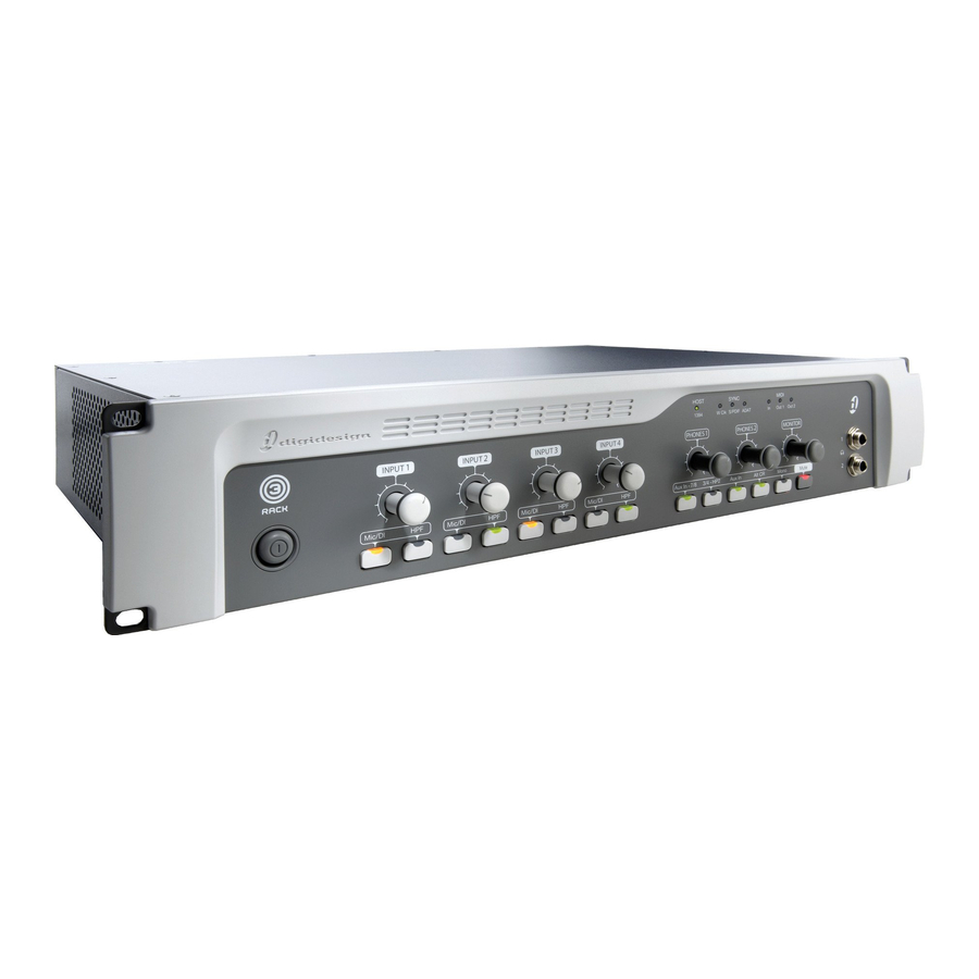
Page 65: Chapter 6. 003 Rack Front Panel
chapter 6 003 Rack Front Panel The 003 Rack front panel provides controls for Inputs 1–4, options for routing outputs and monitor- ing alternate input sources, and indicators for connections status, sync source, and MIDI data. Input 1-4 Gain control Status indicators Power switch Monitor section... -
Page 66: Monitor Section
Aux In signal when Aux In (to Mute is automatically engaged when you power monitor) is enabled. up the unit. Headphone output is not affected by the status of the Monitor Mute switch, but does follow sta- tus of the Mono switch. 003 Family Setup Guide... -
Page 67: Status Indicators
Status Indicators Host (“1394”) Status Indicator The Host status LED, marked “1394” below its LED, indicates that communication has been es- tablished between the unit and Pro Tools LE software (or another software application) through FireWire. Sync Indicators The Sync LEDs indicate the current clock source. When the current clock source is not estab- lished, the respective LED flashes. - Page 68 003 Family Setup Guide...
-
Page 69: Chapter 7. 003 And 003 Rack Back Panels
ADAT Optical I/O (supporting up to front panel. 48 kHz) or two channels of S/PDIF Optical I/O. Digidesign does not recommend the use of All the analog and digital inputs and outputs on unbalanced cables. Unbalanced connec- 003 and 003 Rack support up to 24-bit resolu- tions may introduce noise into your audio tion audio. -
Page 70: Analog Inputs
1/4-inch con- Mic Inputs 1–2 and Mic Inputs 3–4 channel nectors instead. pairs, respectively. Enable these switches for mi- crophones that require phantom power to oper- ate. For more information, see “Phantom Power” on page 78. 003 Family Setup Guide... -
Page 71: Analog Outputs
Analog Inputs 5–8 and Operating Level Monitor Section Switches Main Monitor Outputs Analog Inputs 5–8 are balanced, 1/4-inch TRS jacks for line-level analog audio input connec- These outputs support balanced TRS, or unbal- tions. anced TS, 1/4-inch connections. To monitor your mix, these outputs can be connected to a Operating levels for each of these line-level in- mixing board, directly to a monitoring system... - Page 72 CD recorders and DAT recorders. For highest digital signal integrity, and lower jitter, use 75 Ohm coaxial cable for S/PDIF transfers and keep the cable length to a maximum of 10 meters. 003 Family Setup Guide...
- Page 73 MIDI Studio Setup (Windows). These connec- reliability that makes it ideal for audio applica- tors accept standard 5-pin MIDI cables. tions (such as Pro Tools with 003 family de- vices). FireWire devices can be daisy-chained to- gether without the need for terminators.
-
Page 74: Power Switch
(003 Back Panel Only) 003 family device. This will prevent hard drive errors and data loss in case the 003 family device The Power switch for 003 is located on its back is powered off. -
Page 75: Chapter 8. 003 Rack+ Front Panel
chapter 8 003 Rack+ Front Panel The 003 Rack+ front panel provides controls for Inputs 1–8, options for routing outputs and moni- toring alternate input sources, and indicators for connections status, sync source, and MIDI data. It also includes a single 1/4-inch DI input linked to channel 1. Front Panel DI 1 input Input Channel Gain Controls Status indicators... -
Page 76: Mic And Line/Di Input Controls
When unlit, the selected channel receives input monitor) is enabled. from the mic (XLR) input. Headphone output is not affected by the status of the Monitor Mute switch, but does follow the status of the Mono switch. 003 Family Setup Guide... -
Page 77: Status Indicators
Monitor Level Control These knobs control the Status Indicators volume of the Main and Alt Monitor Outputs. These outputs mirror Analog Outputs 1–2, which correspond to outputs 1–2 in Pro Tools. Host (“1394”) Status Indicator The Host status LED, marked “1394” below its Alternate Input Routing Controls LED, indicates that communication has been es- Aux In to 7/8 Switch This switch routes the Aux... - Page 78 003 Family Setup Guide...
-
Page 79: Chapter 9. 003 Rack+ Back Panel
003 Rack+ analog inputs and plained in this section. outputs, as well as the S/PDIF Digital I/O ports, Digidesign does not recommend the use of support sample rates of 44.1, 48, 88.2, and unbalanced cables. Unbalanced connec- 96 kHz. - Page 80 DI 1 input and you have a line nectors instead. or DI input connected to the rear panel channel 1 Line/DI input, the front panel DI 1 input takes precedence over the rear panel channel 1 Line/DI input. 003 Family Setup Guide...
- Page 81 Analog Outputs Alt Monitor Outputs These outputs support balanced TRS, or unbal- Main Analog Outputs 1–8 anced TS, 1/4-inch connections. These outputs These are impedance balanced, 1/4-inch TRS can be used to monitor your mix through an al- jacks for line-level analog audio output connec- ternate, or secondary studio monitoring system, tions.
-
Page 82: Word Clock
Optical I/O formats in the Pro Tools Hardware Setup dialog. The Optical port can be set for eight channels of ADAT Optical I/O (supporting up to 48 kHz) or two channels of S/PDIF Optical I/O. 003 Family Setup Guide... - Page 83 Pro Tools LE, and is recognized reliability that makes it ideal for audio applica- automatically by Audio MIDI Setup (Mac) and tions (such as Pro Tools with 003 family inter- MIDI Studio Setup (Windows). These connec- faces). FireWire devices can be daisy-chained to- tors accept standard 5-pin MIDI cables.
- Page 84 AC power cable. 003 Rack+ is auto power-selecting (100V to 240V) and will work automatically when plugged into an AC power receptacle in any country. 003 Rack+ requires AC power and cannot be powered by the FireWire bus. 003 Family Setup Guide...
-
Page 85: Chapter 10. Making Studio Connections
Connect headphones with a 1/4-inch stereo ternal sound system (such as powered monitors connector (or adapter) to the Headphone 1 or 2 or a home stereo) to your 003 family interface. jack. Sound from your 003 family interface cannot be played through your computer’s speakers or... - Page 86 TRS or and Outs” on page 84 TS connectors used by and 003 Rack to the RCA connectors on your home ste- To mirror 003 family interface Outputs 1–2 on the S/PDIF outputs: reo. Open the Pro Tools session whose channel Main Monitor Outputs L and R play the audio outputs you want to mirror.
-
Page 87: Connecting Audio Inputs
003 family inputs support microphones, guitars, keyboards, and other types of instruments. Mic Inputs 1-8 003 family interfaces have eight analog inputs. On the 003 and 003 Rack, one set of inputs is la- beled Mic Inputs 1–4 and DI Inputs 1–4, and the other four are labeled Analog 5–8. -
Page 88: Connecting A Microphone
C3000) require phantom power to operate. Dy- namic microphones (such as a Shure SM57) do There are several ways to use your 003 family in- not require phantom power to operate, but are terface with a microphone, depending on the not harmed by it. - Page 89 Depending on your device, do one of the fol- If your microphone requires phantom power, lowing: make sure the microphone is connected and do one of the following depending on your device: • If using the 003 or 003 Rack, press the Mic/DI switch (located on the top panel of •...
- Page 90 DI 1 1/4-inch in- inch connector, do not choose the “Mic” in- put on the front panel (or into a rear-panel put source because the 003 family interface 1/4-inch Line/DI input). will not register any signal.
-
Page 91: Connecting Instruments To 003 Family Interfaces
To use a guitar with the 003 family interface: Connecting Instruments to Do one of the following, depending on your 003 Family Interfaces device: • On the back of the 003 or 003 Rack, plug The 1/4-inch inputs on 003 family interfaces your guitar cable into one of the DI inputs. - Page 92 003 Rack+ with 1/4-inch cable plugged into front panel DI 1 input When Pro Tools is launched and the input is routed to a Pro Tools track, you can adjust the input level with the Input Gain Control knob. 003 Family Setup Guide...
- Page 93 If you are using any DI inputs, press the Set your instrument’s volume to its optimal Mic/DI switch (located on the top panel of the level. For example, the optimal level for most 003, and on the front panel of the 003 Rack) for keyboards is between 80% and 100% of maxi- the corresponding input so that it is in the DI mum volume.
-
Page 94: Connecting Equipment With Digital Ins And Outs
Digital Ins and Outs odd/even pair of inputs. For example, connect the left channel to Line/DI Input 1, and right Each 003 family interface provide up to ten dig- channel to Line/DI Input 2. ital inputs and outputs, including: On the front panel, press the Input Channel •... -
Page 95: Word Clock
Connect the Optical input on the Optical de- priate ports on the other Word clock-capable de- vice to the Optical Out port on the 003 family vices in your studio. interface. (When the 003 or 003 Rack is on, its Optical Out port emits a red light.) -
Page 96: Using External Effects Devices
You can send and return signals to analog de- vices using the analog inputs and outputs on 003 family interfaces. You can also send and re- Pro Tools LE as Word Clock Slave turn a digital signal to an external device that... -
Page 97: Monitoring And Recording From Alternate Sources
Alternate Sources Connect the digital inputs and outputs of the external signal processor to the appropriate dig- 003 family interfaces provide a pair of addi- ital connectors (the S/PDIF RCA connectors or tional inputs for monitoring and recording from the Optical ports) on 003 family interface. -
Page 98: Recording From A Digital Device
• Select Internal if you are synchronizing the S/PDIF format device to the S/PDIF In connector external device to the 003 family interface. on the back of the 003 family interface. You can use the I/O Setup dialog (Setup > Choose Setup > Hardware. -
Page 99: Connecting A Recorder For Mixdowns
Connecting a Digital Deck MIDI Out port of your device to the MIDI In If you have a DAT or other digital device that port on the back panel of the 003 family inter- can receive S/PDIF digital audio data, connect it face. -
Page 100: Using A Footswitch
Connect a footswitch to the footswitch con- to a Line/DI (003 Rack+) input, or to a DI or An- nector on the back panel of the 003 family inter- alog Input on the back panel of the 003 or 003 face. -
Page 101: Chapter 11. Pro Tools Mode With 003
chapter 11 Pro Tools Mode with 003 In Pro Tools mode, the 003 can be used as a con- To put 003 in Pro Tools mode: trol surface for your Pro Tools sessions. Make sure the 003 unit is properly connected to the computer and powered on. -
Page 102: Working In Console View
Press the Pan switch to put 003 in Pan View. View switch is enabled (lit). Press a Channel Select switch that is unlit to There are three Console Views, based on their select the track. corresponding switch name: Pan View, Send View, and Insert View. 003 Family Setup Guide... - Page 103 Hold Shift (Add) and press the Channel Select Renaming Tracks switch for an unselected (unlit) track. To rename a track: All tracks between the first track selected and the Press the Pan switch to put 003 in Pan View. additional track will also be selected. Double-press the Channel Select switch for To remove subsequent tracks in range of selected the track you want to rename.
- Page 104 Hold Command/Ctrl and press the Channel corresponding one (such as Insert A to F or In- Select switch under the plug-in name. sert F to A). The LCD screen displays the name of bypassed plug-ins in all capital letters. 003 Family Setup Guide...
-
Page 105: Working In Channel View
To display the controls for an EQ plug-in: Working in Channel View Press the EQ switch to put 003 in Channel View. Channel View provides a way to temporarily fo- cus on all the plug-ins, inserts or sends on a sin- Press a lit Channel Select switch. - Page 106 Channel Select switches • To display Inserts A–E, press the Page Left will be lit. switch. – or – • To display Inserts F–J, press the Page Right switch. Press the Channel Select switch under a plug-in name. 003 Family Setup Guide...
- Page 107 003 displays the plug-in controls across all chan- In mixed mode situations, where some plug-ins nel strips. Controls are assigned to the rotary en- are bypassed and some are not, pressing the coders. Switched controls (such as Master Bypass Master Bypass switch changes all plug-ins to by- or Phase Invert) are controlled by Channel Se- passed.
-
Page 108: Display Options In Console And Channel View
Press a lit Channel Select switch to display the sends for the corresponding track. Press the Channel Select switch under a send name to toggle its pre- and post-fader setting. 003 Family Setup Guide... - Page 109 Depending on the current Console or Channel To temporarily display insert or plug-in parameters in the LCD (Console or Channel View): View, you can display insert, plug-in, or pan/send settings. Do one of the following: • Make sure the Insert switch is lit in the See “Working in Console View”...
-
Page 110: Creating Custom Plug-In Maps
Close the plug-in window. Choose the map you want to change from the Click the Learn button in a different plug-in plug-in window Map Preset pop-up menu. window. Put the plug-in into Learn mode. 003 displays the plug-in controls. 003 Family Setup Guide... -
Page 111: Navigating And Editing Values In Entry Fields
Do the following for each parameter mapping Navigating and Editing Values you want to change: in Entry Fields • In the plug-in window, click the new plug-in parameter. The parameter name ap- You can navigate and edit numerical values in pears in the plug-in window Parameter Pro Tools windows (such as Selection Start, End, menu. -
Page 112: Assigning Pro Tools Paths (Input, Output, Sends, Inserts)
Channel inputs, outputs, inserts, and sends can be assigned directly from the 003 in Assign Use the rotary encoder to navigate through mode. the available input or output paths in the sub- menu. 003 Family Setup Guide... - Page 113 Do one of the following: Sends • When the desired path is displayed, press To assign a send: the flashing Channel Select to confirm the assignment. Press the Send switch in the Console View sec- tion. If you have multiple assignments in progress, hold Opt/Alt All and press any On the channel where you want to make the flashing Channel Select to save all assign-...
- Page 114 The LCD changes to display the plug-in or out- use the rotary encoder to navigate through the put currently assigned to the selected insert, and the Channel Select switch flashes. available insert paths in the menu. 003 Family Setup Guide...
-
Page 115: Working With Output Windows
Do one of the following: Working with Output Windows • Press the flashing Channel Select to con- firm the assignment. Output windows for tracks and sends can be opened or closed, and the track output can be If you have multiple assignments in made active or inactive. -
Page 116: Recording
Hold Shift (Add)+Opt/Alt (All)+Nudge and ro- the Record Arm switch a second time (or press tate the inner Jog wheel clockwise or the ESC switch). counter-clockwise. Tracks that are armed for recording will remain armed after Rec Arming mode is disabled. 003 Family Setup Guide... -
Page 117: General Editing
Navigating with the Shuttle/Jog Hold Shift and press the Up or Down Arrow key. Wheel Shuttle Mode Setting Selection Start and End Points To play forwards at a variable rate: You can make a selection in the Edit window: Rotate the outer Shuttle ring clockwise. during playback with the Arrow keys. -
Page 118: Working With Memory Locations
Hold Shift (Add) and press the Mem Loc switch. To transfer controls from the rotary encoders to the touch-sensitive faders: To display Memory Locations: Press the Flip switch. This switch flashes when Press the Mem Loc switch. Flip mode is activated. 003 Family Setup Guide... - Page 119 To exit Flip mode (and transfer controls from touch-sensitive faders to edit and automate faders back to the rotary encoders): plug-in control values. The types of plug-in con- trols depend on the particular plug-in you are While in Flip mode, press the Flip switch. using.
-
Page 120: Working With Automation
Fader Mute switch. To mute fader movement: Press the Fader Mute switch so that its LED is flashing. To unmute fader movement: Press the Fader Mute switch so that its LED is unlit. 003 Family Setup Guide... -
Page 121: 003 Top Panel Shortcuts
003 Top Panel Shortcuts 003 provides shortcuts for many common 003 tasks in Pro Tools mode. Display Options Display Options Shortcuts Task Shortcut Display full name of a track in top LCD row Hold Display and press Channel Select switch for a track (Pan mode) Display full name of insert parameter (Insert Hold Display and press Channel Select switch for an... - Page 122 Open or close track Output window (Pan View) Hold Ctrl/Win and press Channel Select switch for a track Open or close multiple track Output windows Hold Ctrl/Win+Shift (Add) and press Channel Select (Pan View) switch for each track 003 Family Setup Guide...
- Page 123 Output Window Shortcuts Task Shortcut Open or close send Output window (Send View) Hold Ctrl/Win and press Channel Select switch for a track send Open or close multiple send Output windows Hold Ctrl/Win+Shift (Add) and press Channel Select (Pan View) switch for each track send Plug-in Shortcuts Plug-in Shortcuts...
- Page 124 Set Automation mode for all tracks Hold Option/Alt All and press Automation switch (Write, Touch, Latch, Read, or Off) Set Automation mode for all selected tracks Hold Option/Alt All+Shift (Add) and press Automation switch (Write, Touch, Latch, Read, or Off) 003 Family Setup Guide...
-
Page 125: Chapter 12. Using Midi Mode With 003
MIDI maps. Each preset can save control your third-party audio application (us- custom maps of two pages of supported con- ing the Digidesign CoreAudio Driver on Mac or trols. 003 provides the following default preset the Digidesign ASIO Driver on Windows). -
Page 126: Selecting Midi Mode
1 of a preset. Press the lit MIDI Map switch (A or B). If you edited a MIDI Map preset without saving, you are prompted to save your changes (see “Saving MIDI Map Presets” on page 121). Bank switch 003 Family Setup Guide... -
Page 127: Recalling Midi Map Presets
Do one of the following: Recalling MIDI Map Presets • To confirm and load the preset, select OK by pressing the Master Bypass switch (Mas- To recall a MIDI Map preset (A1–4 or B1–4) from ter Bypass). flash memory: – or – Press either the MIDI Map A switch or the •... -
Page 128: Mapping Controls
PL, and RC) by default, but can be re-assigned to each switch. any CC number. Switches can be set to Momentary or Latch mode (see “Momentary or Latch Mode” on page 120). Transport controls • Footswitch 003 Family Setup Guide... -
Page 129: Editing Midi Map Presets
The following controls are not assignable in The switch’s LED flashes, and the LCD display MIDI mode: shows parameters similar to the following tables (which show default assignments for Fader 1 as • Mic/DI Input controls an example): • Monitor section controls MIDI Edit display, channels 1–4 (Fader 1 example) •... - Page 130 The cursor flashes for the se- Select the switch you want to edit. lected character. Turn the rotary encoder for channel 7 (Mode) Repeat steps 3–4 for the remaining characters to select Latch or Momnt (momentary). of the control name. 003 Family Setup Guide...
-
Page 131: Naming Midi Map Presets
Naming MIDI Map Presets Saving MIDI Map Presets MIDI Map presets can have custom names of up Presets are snapshots of MIDI mapping assign- to 28 characters. This makes it easier to manage ments that can be saved and recalled. You can multiple presets for different devices. -
Page 132: Factory Default
The selected MIDI Map preset is overwritten by its default preset. – or – • To cancel without overwriting flash mem- ory and the selected preset with its factory default preset, select Cancel by pressing the ESC switch. 003 Family Setup Guide... - Page 133 Standard MIDI Map Preset Table 13. Default Standard MIDI Map, presets A1 and B1 Controller MIDI Channel Mode Name LoVal/HiVal PAGE 1 Latch Local 0–127 Dynmcs1 Latch AllOff 0–127 Insert1 Latch OmniOn 0–127 PanSnd1 Latch OmniOff 0–127 Page <1 Latch MonoOn 0–127 Page >1...
- Page 134 Encdr1 Encdr1 0–127 Encdr2 Encdr2 0–127 Encdr3 Encdr3 0–127 Encdr4 Encdr4 0–127 Encdr5 Encdr5 0–127 Encdr6 Encdr6 0–127 Encdr7 Encdr7 0–127 Encdr8 Encdr8 0–127 Fader1 Fader1 0–127 Fader2 Fader2 0–127 Fader3 Fader3 0–127 Fader4 Fader4 0–127 003 Family Setup Guide...
- Page 135 Table 13. Default Standard MIDI Map, presets A1 and B1 Controller MIDI Channel Mode Name LoVal/HiVal Fader5 Fader5 0–127 Fader6 Fader6 0–127 Fader7 Fader7 0–127 Fader8 Fader8 0–127 REW1 — MMC RW Moment — MMC FF Moment STOP1 — MMC ST Moment STOP PLAY1...
- Page 136 Slct15 NoAsgn Latch Slct 15 Slct16 NoAsgn Latch Slct 16 Solo 9 Latch Solo 9 0–127 Solo10 Latch Solo 10 0–127 Solo11 Latch Solo 11 0–127 Solo12 Latch Solo 12 0–127 Solo13 Latch Solo 13 0–127 003 Family Setup Guide...
- Page 137 Table 13. Default Standard MIDI Map, presets A1 and B1 Controller MIDI Channel Mode Name LoVal/HiVal Solo14 Latch Solo 14 0–127 Solo15 Latch Solo 15 0–127 Solo16 Latch Solo 16 0–127 Mute 9 Latch Mute 9 0–127 Mute10 Latch Mute 10 0–127 Mute11 Latch...
- Page 138 0–127 Nav Right2 Moment Nav R 0–127 Rec Arm2 Latch RecArm 0–127 PanMd2 Latch Pans 0–127 SndMd2 Latch Sends 0–127 InsMd2 Latch Insert 0–127 A/F2 Latch 0–127 B/G2 Latch 0–127 C/H2 Latch 0–127 D/I2 Latch 0–127 003 Family Setup Guide...
- Page 139 Table 13. Default Standard MIDI Map, presets A1 and B1 Controller MIDI Channel Mode Name LoVal/HiVal E/J2 Latch 0–127 Footswitch2 Moment Footsw 0–127 003 Map Preset Table 14. Default 003 Map, presets A2 and B2 Controller MIDI Channel Mode Name LoVal/HiVal PAGE 1 Latch...
- Page 140 Mute 6 0–127 Mute 7 Latch Mute 7 0–127 Mute 8 Latch Mute 8 0–127 Encdr1 Encdr1 0–127 Encdr2 Encdr2 0–127 Encdr3 Encdr3 0–127 Encdr4 Encdr4 0–127 Encdr5 Encdr5 0–127 Encdr6 Encdr6 0–127 Encdr7 Encdr7 0–127 003 Family Setup Guide...
- Page 141 Table 14. Default 003 Map, presets A2 and B2 Controller MIDI Channel Mode Name LoVal/HiVal Encdr8 Encdr8 0–127 Fader1 Fader1 0–127 Fader2 Fader2 0–127 Fader3 Fader3 0–127 Fader4 Fader4 0–127 Fader5 Fader5 0–127 Fader6 Fader6 0–127 Fader7 Fader7 0–127 Fader8 Fader8 0–127 REW1...
- Page 142 Slct11 NoAsgn Latch Slct 11 0–127 Slct12 NoAsgn Latch Slct 12 0–127 Slct13 NoAsgn Latch Slct 13 0–127 Slct14 NoAsgn Latch Slct 14 0–127 Slct15 NoAsgn Latch Slct 15 0–127 Slct16 NoAsgn Latch Slct 16 0–127 003 Family Setup Guide...
- Page 143 Table 14. Default 003 Map, presets A2 and B2 Controller MIDI Channel Mode Name LoVal/HiVal Solo 9 Latch Solo 9 0–127 Solo10 Latch Solo 10 0–127 Solo11 Latch Solo 11 0–127 Solo12 Latch Solo 12 0–127 Solo13 Latch Solo 13 0–127 Solo14 Latch...
- Page 144 0–127 Nav Down2 Moment Nav Dn 0–127 Nav Left2 Moment Nav L 0–127 Nav Right2 Moment Nav R 0–127 Rec Arm2 Latch RecArm 0–127 PanMd2 Latch Pans 0–127 SndMd2 Latch Sends 0–127 InsMd2 Latch Insert 0–127 003 Family Setup Guide...
- Page 145 Table 14. Default 003 Map, presets A2 and B2 Controller MIDI Channel Mode Name LoVal/HiVal A/F2 Latch 0–127 B/G2 Latch 0–127 C/H2 Latch 0–127 D/I2 Latch 0–127 E/J2 Latch 0–127 Footswitch2 Moment Footsw 0–127 Strike Map Preset Table 15. Default Strike Map, presets A3 and B3 Controller MIDI Channel Mode...
- Page 146 Mute 5 Latch Mute 5 0–127 Mute 6 Latch Mute 6 0–127 Mute 7 Latch Mute 7 0–127 Mute 8 Latch Mute 8 0–127 Encdr1 Pan 1 0–127 Encdr2 Pan 2 0–127 Encdr3 Pan 3 0–127 003 Family Setup Guide...
- Page 147 Table 15. Default Strike Map, presets A3 and B3 Controller MIDI Channel Mode Name LoVal/HiVal Encdr4 Pan 4 0–127 Encdr5 Pan 5 0–127 Encdr6 Pan 6 0–127 Encdr7 Pan 7 0–127 Encdr8 Pan 8 0–127 Fader1 Vol 1 0–127 Fader2 Vol 2 0–127 Fader3...
- Page 148 Scrol< 0–127 Page >2 Moment Scrol> 0–127 MstByp2 Latch MstFdr 0–127 Esc2 Latch Latch 0–127 Slct 9 Latch Ins 9 0–127 Slct10 Latch Ins 10 0–127 Slct11 Latch Ins 11 0–127 Slct12 Latch Ins 12 0–127 003 Family Setup Guide...
- Page 149 Table 15. Default Strike Map, presets A3 and B3 Controller MIDI Channel Mode Name LoVal/HiVal Slct13 Latch Ins OH 0–127 Slct14 Latch Ins Rm 0–127 Slct15 Latch Ins TB 0–127 Slct16 Latch Ins Ms 0–127 Solo 9 Latch Solo 9 0–127 Solo10 Latch...
- Page 150 PLAY2 — MMC PL Moment PLAY RECORD2 — MMC RC Moment RECORD RTZ2 NoAsgn Moment NoAsn Nav Up2 NoAsgn Latch NoAsn Nav Down2 NoAsgn Latch NoAsn Nav Left2 NoAsgn Latch NoAsn Nav Right2 NoAsgn Latch NoAsn 003 Family Setup Guide...
- Page 151 Table 15. Default Strike Map, presets A3 and B3 Controller MIDI Channel Mode Name LoVal/HiVal Rec Arm2 NoAsgn Latch NoAsn PanMd2 NoAsgn Latch NoAsn SndMd2 NoAsgn Latch NoAsn InsMd2 NoAsgn Latch NoAsn A/F2 NoAsgn Latch NoAsn B/G2 NoAsgn Latch NoAsn C/H2 NoAsgn Latch...
- Page 152 003 Family Setup Guide...
-
Page 153: Appendix A. Utility Mode (003 Only)
appendix a Utility Mode (003 Only) 003 is in this mode when the Utility switch is Accessing Utility Mode enabled (flashing). In Utility mode, you can run pre-programmed diagnostic tests of the 003 To enter Utility mode: unit. The Utility switch is unavailable in Pro Tools mode. -
Page 154: Viewing Firmware Version Data
– or – enabled (flashing), press it. • To cycle through all the LEDs, press the flashing Insert switch. Select the Test menu by pressing the flashing Insert switch. To exit the test at anytime, press any switch. 003 Family Setup Guide... -
Page 155: Switch Test
Rotate any encoder (or the Jog/Shuttle wheel) Switch Test to test it. Encoder value is displayed in the LCD while testing. Use this test to evaluate the performance of switches. To exit the test at anytime, press the Display Mode switch. To test switches: Enter Utility mode. -
Page 156: Vegas Mode
Enter Utility mode. If the Utility switch is not enabled (flashing), press it. Select the Test menu by pressing the flashing Insert switch. The LCD shows the first page of Utility tests. Select the Fader menu by pressing the flashing Page Right switch. 003 Family Setup Guide... -
Page 157: Midi Test
MIDI Test Audio Test 003 includes a MIDI loopback test to check 003 includes audio loopback tests (see “Routing MIDI input and output connections. A standard Path for Audio Tests” on page 148) to check var- 5-pin MIDI cable is required. ious audio connections. - Page 158 Simultaneous routing of S/PDIF (RCA) Inputs to Analog Outputs 1–2 and Analog Inputs 1–2 to S/PDIF (RCA) Outputs. Adat Simultaneous routing of ADAT Optical Inputs to Analog Outputs 1–8 and Analog Inputs 1–8 to ADAT Optical Outputs. 003 Family Setup Guide...
-
Page 159: Appendix B. Configuring Ams (Mac Os X Only)
appendix b Configuring AMS (Mac OS X Only) Click the MIDI Devices tab. AMS scans your Audio MIDI Setup system for connected MIDI interfaces. If your MIDI interface is properly connected, it appears Pro Tools recognizes the ports on your MIDI in- in the window with each of its ports numbered. - Page 160 MIDI devices, row of the corresponding port of the MIDI inter- named “Digidesign Device List.middev.” If face. the Manufacturer or Model names for any of your external MIDI devices is not available...
- Page 161 Click the More Properties arrow to expand the Click the device image. The window expands dialog, then enable the appropriate MIDI chan- to show images for various MIDI devices (such nels (1–16) for the Transmits and Receives op- as keyboards, modules, interfaces, and mixers). tions.
-
Page 162: Patch Name Support
Patch Select button Patch Select button (Edit window) (Mix window) ited in any text editor, or you can use third- party patch librarian and editor software to Patch Select button create your own custom patch names. 003 Family Setup Guide... -
Page 163: Appendix C. Configuring Midi Studio Setup (Windows Only)
appendix c Configuring MIDI Studio Setup (Windows Only) MIDI Studio Setup Window MIDI Studio Setup The MIDI Studio Setup window is organized MIDI Studio Setup (MSS) lets you configure the into three sections. Interface controls are at the MIDI controllers and sound modules that are top of the window. - Page 164 Manufacturer and Model pop-up menus do not provide a name for your particular device, select None. From the Input pop-up menu, select the input port on your MIDI interface that is connected to the MIDI Out of your instrument. 003 Family Setup Guide...
-
Page 165: Midi Patch Name Support
MIDI patch name files (.midnam) for the factory default patch names of many common MIDI devices. These files reside in directories, sorted by manufacturer, in C:\Program Files\ Common Files\Digidesign\MIDI Patch Names\ Digidesign. Appendix C: Configuring MIDI Studio Setup (Windows Only) - Page 166 Change button Patch Select dialog In the Open dialog, navigate to C:\Program Files\Common Files\Digidesign\MIDI Patch Names\Digidesign\<name of manufacturer>, and select the MIDI Patch Name file (.midnam) for the MIDI device. Click Open. 003 Family Setup Guide...
-
Page 167: Appendix D. Hard Drive Configuration And Maintenance
Beat Detective in a session. For complete hard drive requirements, visit the Digidesign website at: www.digidesign.com/compatibility Appendix D: Hard Drive Configuration and Maintenance... -
Page 168: Formatting An Audio Drive
For complete information on track count and To format an audio drive: the supported number and configuration of Launch the Disk Utility application, located in SCSI drives, visit the Digidesign website at: Macintosh HD/Applications/Utilities. www.digidesign.com/compatibility Click the Erase tab. FireWire Hard Drives... -
Page 169: Partitioning Drives
Next. To format an audio drive: • When prompted, select the partition type. Right-click Computer (Windows Vista) or My Digidesign recommends using Primary par- Computer (Windows XP) and choose Manage. titions, instead of Extended partitions. Under Storage, choose Disk Management. -
Page 170: Defragmenting An Audio Drive
003 Family Setup Guide... -
Page 171: Using Mac Drives On Windows Systems
Defragmenting Windows Audio Drives Using Mac Drives on Windows Systems To defragment an audio drive (Windows Vista): Choose Start > Control Panel. Pro Tools for Windows lets you record and play back sessions directly from a Mac-formatted Click System and Maintenance. (HFS+) drive connected to a Windows system. -
Page 172: Hard Disk Storage Space
24 mono tracks, 60 minutes 7 GB 7.8 GB 10.5 GB 11.6 GB 32 mono tracks, 5 minutes 800 MB 883 MB 1.2 GB 1.3 GB 32 mono tracks, 60 minutes 9.4 GB 10.4 GB 14 GB 15.4 GB 003 Family Setup Guide... - Page 173 Mono audio tracks recorded with 24-bit resolution at 96 kHz require approximately 16.5 MB of hard disk space per minute (a little more than twice as much as at 44.1 kHz). Stereo audio tracks recorded with 24-bit resolution at 96 kHz require about 33 MB per minute. Table 6 lists the required disk space for certain track numbers and track lengths at 88.1 and 96 kHz, to help you estimate your hard disk usage.
- Page 174 003 Family Setup Guide...
-
Page 175: Appendix E. Troubleshooting
appendix e Troubleshooting Backing Up Your System Backing Up Your Work Configuration It is highly recommended that you back up your After configuring your system and Pro Tools, work on a regular basis, and especially before you should save an image of your system drive making changes to your system configuration. -
Page 176: Common Issues
Pro Tools. Power Saver Features Some automatic power saver features, such as those that spin down the system hard drive, can affect Pro Tools perfor- mance. These features should be turned off. 003 Family Setup Guide... -
Page 177: Before You Call Digidesign Technical Support
• Amount of system RAM To verify that your hardware is qualified for use • Operating system (version of Mac or Win- with your Pro Tools system, visit the Digidesign website (www.digidesign.com/compatibility). dows) • Any Drivers, Disk Utilities, or other system-... - Page 178 Note any DAE errors or other error codes you en- counter. Additonally, note the ability to repro- duce the problem under different conditions, for example, with another session, or after changing settings (such as the Hardware Buffer Size). 003 Family Setup Guide...
-
Page 179: Appendix F. Resources
Guide and other guides in the Pro Tools guide Tools. set can be purchased separately from the • DigiRack Plug-ins Guide, which describes the DigiStore (www.digidesign.com). DigiRack plug-ins included with Pro Tools for both real-time and file-based audio process- Printed Setup Guide ing. -
Page 180: About Www.digidesign.com
News and Events Get the latest news from To view or print PDF guides, you can use Digidesign or sign up for a Pro Tools demo. Adobe Reader or Apple Preview (Mac only). Pro Tools Accelerated Videos Watch the series of Read Me Files free tutorial videos. -
Page 181: Index
index Numerics AC power connector 64, 74 1394 LED 39 ADAT Display section 38 connecting 85, 89 Fader section 40 LED (003 Rack) 57 Headphone jacks 54 LED (003 Rack+) 67 LCD display 38 LED (003) 39 Monitor section 54 Optical I/O 62, 72 Power switch 64 additional software... - Page 182 Direct Interface inputs (003 and 003 Rack) 60 Right 43 Display Mode switch 39 Channel Select switches 41 Display section 38 Channel View 95 Display switches 50 switches 46 switches in MIDI mode 118 Clean Uninstall (Mac) 10 Clock Source 25 003 Family Setup Guide...
- Page 183 displaying channel pan setting and send levels in Channel View 95 temporarily 99 EQ plug-ins Dynamics plug-in controls 96 cycling through 95 Dynamics plug-ins on a track 95 displaying all on a track 95 EQ plug-in controls 95 displaying controls 95 EQ plug-ins on a track 95 EQ switch 47 fader level temporarily 99...
- Page 184 63, 73 Ignore Errors During Playback/Record option 22 Kensington Lock port 63 Input 1–4 Gain controls keyboards 003 53 connecting 82 003 Rack 55 knobs (see rotary encoders) Input 1-8 Gain controls (003 Rack+) 66 003 Family Setup Guide...
- Page 185 MIDI connections 89 Latch Automation editing maps in MIDI mode 120 LED 52 monitoring 90 switch 52 requirements 3 launching Pro Tools 7, 14 setup (Mac) 149 setup (Windows) 153 display 38 Stand-alone CC assign 120 test 144 Stand-alone channel assign 120 LEDs test 147 Automation modes 52...
- Page 186 Plug-in Flip mode 109 Plug-in Master Bypass switch 47 Plug-in Streaming Buffer 24 Automation LED 52 Plug-in Streaming Buffer Size 24 Automation switch 52 Plug-in switch 50 OK switch 51 Operating Level switches 61 operating levels 59, 69 003 Family Setup Guide...
- Page 187 plug-ins Pro Tools mode 91 bypassing all 97 adding comments 102 bypassing one 97 Assign mode 102 displaying controls 94, 96 assigning inputs and outputs 102 multiprocessors 21 assigning inserts 104 RTAS Processors setting 21 assigning sends 103 toggling views 51 automation 110 banking channels 109 power 64, 74...
- Page 188 110 LED (003 Rack+) 67 LED (003) 39 Safe Uninstall (Mac) 10 sample rate 59, 69 default 25 Save switch 51 saving a session (003) 91 screen savers 166 scrolling the Edit window 107 003 Family Setup Guide...
- Page 189 switches Page 47 3/4-HP 2 (003 Rack) 56, 67 Pan 46 3/4-HP 2 (003) 54 Pan/Send 47 Phantom Power 60 Alt CR (003 Rack) 56 Alt CR (003 Rack+) 67 Plug-in Master Bypass 47 Alt CR (003) 54 Plug-in window 50 QuickPunch 50 Automation modes 52 Aux In (to Monitor) (003 Rack) 56, 67...
- Page 190 Encoder test exiting 144 Fader Group test 146 Fader tests 145 firmware version 144 LCD test 144 LED test 144 MIDI test 147 navigating 143 Switch test 145 Touch test 146 Vegas mode 146 Utility switch 51 003 Family Setup Guide...
- Page 191 DIGIDESIGN TECHNICAL SUPPORT (USA) PRODUCT INFORMATION (USA) INTERNATIONAL OFFICES Visit the Digidesign website 2001 Junipero Serra Boulevard Tel: 650.731.6100 Tel: 800.333.2137 for contact information Daly City, CA 94014-3886 USA Fax: 650.731.6375 Tel: 650.731.6300 Fax: 650.731.6399...
Need help?
Do you have a question about the 003 Family and is the answer not in the manual?
Questions and answers
How do I record to tracks using digidesign mixer audacity