Advertisement
Available languages
Available languages
Quick Links
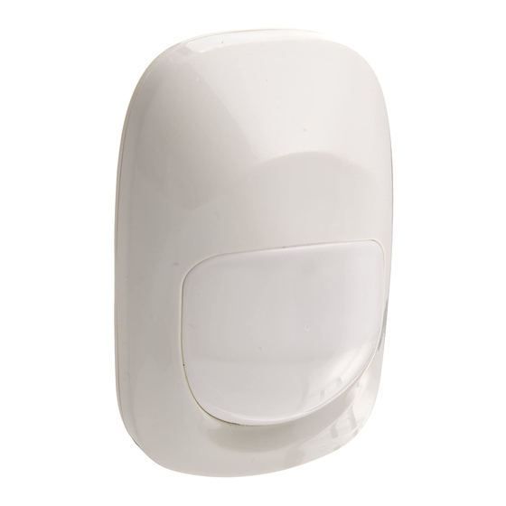
Vi-motion, Vi-Pet
PIR / Pet immune Digital Detectors Installation Instructions
English
Español
Instrucciones de Instalación de Detectores Digitales PIR /
Inmume a mascotas
Portuguese
Instruções de instalação de Detectores Digitais PIR / Imune a
animais
ENGLISH
1. INTRODUCTION
The Vi-motion and Vi-Pet (pet immune) are digital PIR detectors,
designed for easy installation, free of vertical adjustment. They
include a patented combination of Fresnel and cylindrical optical
system with high-detection sensitivity beginning at 0.5 meter away
from the detector up to a distance of 12 meters (40 ft). The detectors
have full true digital temperature compensation.
As a pet immune motion detector, the Vi-Pet utilizes TSI™ (Target
Specific Imaging) technology that ensures immunity to pets weighing
up to 27 kg (60 lb).
Advanced True Motion Recognition™ algorithm (patented) allows the
detectors to distinguish between true motion of an intruder and other
disturbances that cause false alarms. An on-board motion event
selector enables to choose whether 1 or 2 consecutive motion events
will trigger an alarm. A TST (Test) input permits detector switching to
walk test mode remotely without opening the detector.
2. SPECIFICATIONS
Input Voltage: 9 to 16 VDC.
Current Drain: Max. 9 mA @ 12 VDC
OPTICAL (see Fig. 2)
Lens Data
No. of curtains:
Vi-motion: 46, equivalent to 214 beams.
Vi-Pet: 36, equivalent to 196 beams.
Max. Coverage: 12 x 12 m (40 x 40 ft) / 90°
Pet Immunity (Vi-Pet only) : Animals up to 27 kg (60 lb)
ALARM and TAMPER
Alarm Output: Solid-state relay, N.C., up to 100 mA / 30 V,
~
30 Ω internal resistance. Circuit opens for 2-3 seconds upon alarm.
Alarm Indication: LED lights for 2-3 seconds.
Event Counter: Selectable, 1 or 2 motion events.
Tamper Output: Normally closed, 50 mA resistive / 30 VDC.
MOUNTING
Surface or corner, at the height of 1.8 to 2.4 m (6 to 8 ft)
Note: Base allows single-sided corner mount at 45° to wall.
ACCESSORIES:
BR-1: Surface mounted swivel bracket, adjustable 30° down and 45°
left/45° right.
BR-2: BR-1 with a corner adapter.
BR-3: BR-1 with a ceiling adapter.
ENVIRONMENTAL
Operating Temperature: –10°C to 50°C (14°F to 122°F)
Storage Temperature: –20°C to 60°C (–4°F to 140°F)
RFI Protection: Greater than 20 V/m (20 MHz to 1000 MHz)
Compliance with Standards: EN 50131-1 Grade 2, Class II
PHYSICAL
Size (H x W x D): 80 x 50 x 37 mm (3-1/8 x 1-15/16 x 1-7/16")
Weight: Approximately 77 g (2-3/4 oz)
PATENTS: U.S. Patents 5,693,943
6,768,294 (other patents pending)
3. INSTALLATION
3.1 General Guidance
1. Keep away from heat sources.
2. Do not expose to air drafts.
3. Do not install outdoors.
4. Avoid direct sunshine.
D-1009-EPS
6,211,522
6,818,881,
(see fig. 3)
5. Keep wiring away from power
cables.
6. Do not install behind partitions.
7. Mount on solid stable surface.
GB/US: Walk-Test LED
SP: LED del test de andado
PT: LED do teste de passagem
3.2 Installation Procedure
1. Mounting - see fig. 4.
2. Jumpers settings - see fig. 5.
3. Wiring – See fig. 6.
4. Walk-test - see fig. 2. Perform walk across the far end of
coverage pattern in both directions. The LED should light for
2-3 seconds each time your motion is detected.
Important! Instruct the user to perform walk test at least once
a week to verify proper function of the detector.
4. SPECIAL COMMENTS
4.1 Product Limitations
Although this detector is a highly reliable device, it does not guarantee
complete protection against intrusion. Even the most sophisticated detectors
can sometimes be defeated or may fail to warn because:
A. The detector will not function if the DC power supplied to it is incorrect
or improperly connected.
B. A PIR detector does not provide full volumetric coverage. It can only
detect motion that disturbs the sensitive beams spread within the
protected area.
C. Motion is not detected if it takes place behind closed doors, walls,
glass partitions, windows and shutters.
D. The detection ability of the PIR detector may be reduced by malicious
masking or by spraying various materials on the lens or by mechanical
tampering with the optical system.
E. The PIR detector's performance depends on the temperature
difference between the environment and the human body. If this
difference is too small, the PIR performance may decrease.
F. Even the most reliable electrical devices, including this detector, may
go wrong due to an unexpected failure of a component part.
The above list includes the most common reasons for failure to detect
intrusion, but it is by no means comprehensive. It is therefore
recommended that the detector and the entire alarm system be checked
weekly, to ensure proper performance.
An alarm system should not be regarded as a substitute for insurance.
Home and property owners or renters should be prudent enough to
continue insuring their lives and property, even though they are protected
by an alarm system.
4.2 Compliance with FCC Standards
This device has been tested and found to comply with the limits for a Class B
digital device, pursuant to Part 15 of the FCC Rules. These limits are
designed to provide reasonable protection against harmful interference in
residential installations. This equipment generates, uses and can radiate
radio frequency energy and, if not installed and used in accordance with the
instructions, may cause harmful interference to radio and television
reception. However, there is no guarantee that interference will not occur in
a particular installation. If this device does cause such interference, which
can be verified by turning the device off and on, the user is encouraged to
eliminate the interference by one or more of the following measures:
– Re-orient or re-locate the receiving antenna.
– Increase the distance between the device and the receiver.
– Connect the device to an outlet on a circuit different from the one which
supplies power to the receiver.
– Consult the dealer or an experienced radio/TV technician.
WARNING! Changes or modifications to this unit not expressly
approved by the party responsible for compliance could void the
user's authority to operate the equipment.
W.E.E.E. Product Recycling Declaration
For information regarding the recycling of this product you must contact
the company from which you orignially purchased it. If you are discarding
this product and not returning it for repair then you must ensure that it is
returned as identified by your supplier. This product is not to be thrown
away with everyday waste.
European
Directive
2002/96/EC
Equipment.
GB/US: Lens
SP: Lente
PT: Lente
Fig. 1 - Vi-motion / Vi-Pet
Waste
Electrical
and
Electronic
1
Advertisement

Subscribe to Our Youtube Channel
Related Manuals for Visonic Vi-motion


Summary of Contents for Visonic Vi-motion
-
Page 1: Installation Procedure
3.2 Installation Procedure 1. INTRODUCTION 1. Mounting - see fig. 4. The Vi-motion and Vi-Pet (pet immune) are digital PIR detectors, 2. Jumpers settings - see fig. 5. designed for easy installation, free of vertical adjustment. They 3. Wiring – See fig. 6. - Page 2 3.2 Procedimiento de instalación 1. INTRODUCCION 1. Montaje - vea fig. 4. El Vi-motion y el Vi-Pet (inmune a mascotas) son detectores digitales 2. Configuración de jumpers - vea fig. 5. PIR, diseñados para una fácil instalación, libres de ajuste vertical.
- Page 3 3.2 Procedimento de instalação 1. Montagem - veja fig. 4. O Vi-motion e o Vi-Pet (imune a animais) são detectores digitais PIR, 2. Configuração dos jumpers - veja a fig. 5. desenhado para uma fácil instalação, livres de ajustes verticais.
- Page 4 FRASER ROAD, PRIORY BUSINESS PARK, BEDFORD MK44 3WH. PHONE: (0870) 730-0800 FAX: (0870) 730-0801 VISONIC IBERICA SEGURIDAD, SL: C/ ISLA DE PALMA, 32 - NAVE 7, POLÍGONO INDUSTRIAL NORTE, 28700 SAN SEBASTIÁN DE LOS REYES, (MADRID), ESPAÑA. TEL (34) 91659-3120, FAX (34) 91663-8468. www.visonic-iberica.com VISONIC SICHERHEITSTECHNIK GMBH : ROMANEYER STR.
Need help?
Do you have a question about the Vi-motion and is the answer not in the manual?
Questions and answers