Advertisement
Quick Links
DUO 240
DUO 240
DUO 240
DUO 240
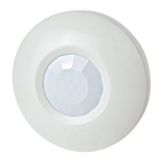
Ceiling-Mount Dual Technology Intrusion Detector
1. INTRODUCTION
1. INTRODUCTION
1. INTRODUCTION
1. INTRODUCTION
DUO 240 is a microcomputer-controlled, ceiling-mounted dual-
technology intrusion detector. Its operation is based on two
physical phenomena - the infrared (IR) radiation emitted by the
human body and the Doppler frequency shift caused by a person
moving in a microwave (MW) field. The IR and MW technologies,
when combined in a single detector, complement each other to
assure the most reliable detection and immunity to false alarms.
The superiority of the DUO 240 over other dual detectors has
been achieved by the advent of a True Motion Recognition™
2. SPECIFICATIONS
2. SPECIFICATIONS
2. SPECIFICATIONS
2. SPECIFICATIONS
Input Voltage: 9 to 16 VDC (Nominal: 12 VDC)
Current Drain: About 30 mA @ 12 VDC
PIR SECTION
Detector: Low noise dual-element pyroelectric sensor
Trip Indication: Green LED flashes for up to 5 seconds
True Motion Event Verification Counter: 1 or 2 events
Detection Pattern: A virtually conical pattern of maximum 10.8 m
(35 ft) diameter, when installed on a 4.5 m (15 ft) ceiling (Fig. 1).
Mounting on a lower ceiling will reduce the coverage area.
MW SECTION
Oscillator: Microstrip DRO-stabilized type
Frequency: 2.45 GHz
Detection Range: Adjustable from 25% to 100%
Trip Indication: Green LED lights for up to 5 seconds
ALARM, TAMPER & TROUBLE DATA
Alarm Indication: Red LED lights for 2-3 s (both detectors trip)
Relay Contacts: Normally closed, 0.1 A resistive/30 VDC; 47 Ω
resistor in series with contacts
Alarm Duration: 2-3 seconds (red LED lights and output relay
contacts open)
Tamper Contacts: Normally closed, 50 mA resistive/ 30 VDC
Trouble Output: Open-collector, 100 mA max. serial resistor
47 Ω, pull-up resistor 47 KΩ (see Fig. 4)
MOUNTING AND PHYSICAL DATA
Maximum Mounting Height: 4.5 m (15 ft)
Dimensions (H x Ø): 24 x 86 mm (3.4 x 0.95 in.)
Weight: 64 g (2 oz)
Color: White
ATTENTION! Detection occurs only in areas in which the MW and PIR patterns overlap.
3. 3. 3. 3. INSTALLATION
INSTALLATION
INSTALLATION
INSTALLATION
3.1 General Guidelines
A few important rules must be observed before selecting a
mounting location.
Microwave radiation passes through glass and nonmetallic
•
walls and floors. Be sure to adjust the MW range to the
necessary minimum, to reduce the possibility of interference
from lower floors.
Large reflecting objects (especially metals) within the
•
coverage area can distort the microwave detector's coverage
pattern.
Although the DUO 240 is extremely immune to air turbulence
•
and RF interference, avoid installation in a room with very
DE1826
Installation Instructions
algorithm (patented). This advanced motion analysis method
provides the DUO 240 with the ability to distinguish between the
true motion of a human body and any other disturbances which
invariably cause false alarms.
Another unique feature of the DUO 240 is the MW Motion
Simulator circuit (patents applied for), which simulates the effect
created by a human body moving in the MW field. The simulation
routine is carried out periodically for self-testing, supervision and
assurance that the MW detector operates properly.
SIDE VIEW
2.4 m
(8 ft)
TOP VIEW
Figure 1. DUO 240 Coverage Pattern
ENVIRONMENTAL CONDITIONS
Operating Temperature: –10° C to 50° C (14° F to 122° F)
Storage Temperature: –20° C to 60° C (–4° F to 140° F)
RFI Protection: Greater than 20 V/m (20 to 1000 MHz)(Not UL
investigated)
PATENTS
U.S. Patents 5,237,330 and 5,693,943 (other patents pending)
Compliance with standards: EN 50131-1 Grade 2 Class II, UL-639
strong air drafts or close to high-power electrical cables. It is
also recommended to avoid aiming the detection pattern at
sources of bright light and/or heat.
If two DUO 240 units are installed in the same room, they
•
should be mounted at least 2 m (6 ft) apart.
Always mount the unit on a firm and stable ceiling and
•
remember that the height above the floor determines the size
of the circular coverage pattern.
Do not install the DUO 240 in places where one of the two
•
detectors
alarms
constantly
environmental interference.
PIR
4.5 m
4.8 m (16 ft)
(15 ft)
10.8 m (35 ft)
or
intermittently,
due
to
1
Advertisement

Summary of Contents for Visonic DUO 240
-
Page 1: Installation Instructions
• coverage area can distort the microwave detector's coverage of the circular coverage pattern. pattern. Do not install the DUO 240 in places where one of the two • Although the DUO 240 is extremely immune to air turbulence detectors... - Page 2 After connecting the (+) and (–) terminals to the power source, within 60 seconds, a failure has been detected by the self-test the DUO 240 starts a 60-second warm-up period, indicated by circuitry and the TRB output is activated alternate...
- Page 3 4. INDICATORS AND SELECTORS 4. INDICATORS AND SELECTORS 4. INDICATORS AND SELECTORS 4. INDICATORS AND SELECTORS 4.1 LED Indications 4.2 Mode Selector The two LEDs (Fig. 3), which are hidden behind the lens when The DIP switch mode the cover is installed, are visible through the lens when selector is mounted on illuminated.
- Page 4 VISONIC INC. (U.S.A.): 65 WEST DUDLEY TOWN ROAD, BLOOMFIELD CT. 06002-1376. PHONE: (860) 243-0833, (800) 223-0020. FAX: (860) 242-8094 VISONIC LTD. (UK): UNIT 6 MADINGLEY COURT CHIPPENHAM DRIVE KINGSTON MILTON KEYNES MK10 0BZ. TEL: (0870) 7300800 FAX: (0870) 7300801. TEL: (0870) 7300800 FAX: (0870) 7300801 PRODUCT SUPPORT: (0870) 7300830 VISONIC GmbH (D-A-CH): KIRCHFELDSTR.


Need help?
Do you have a question about the DUO 240 and is the answer not in the manual?
Questions and answers