Table of Contents
Advertisement
Quick Links
© 2011, Moog Videolarm, Inc. All Rights Reserved
F D W 7 5 C 8
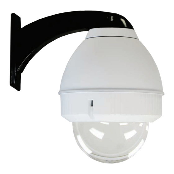
Fusion Dome (Ultra high PoE)
Installation and Operation Instructions for the following models:
FDW75C8N
IP Network Ready 7" Outdoor dome housing with wall mount, clear dome, PoE
input, heater/blower, fan
FDP75C8N
IP Network Ready 7" Outdoor dome housing with pendant mount, clear dome, PoE
input, heater/blower, fan
FDW75T8N
IP Network Ready 7" Outdoor dome housing with wall mount, tinted dome, PoE
input, heater/blower, fan
FDP75T8N
IP Network Ready 7" Outdoor dome housing with pendant mount, tinted dome, PoE
input, heater/blower, fan
Before attempting to connect or operate this product, please read these instructions completely.
www.videolarm.com
81-IN5471
01-31-2012
Advertisement
Table of Contents

Subscribe to Our Youtube Channel
Related Manuals for Moog Videolarm FDW7 5C8


Summary of Contents for Moog Videolarm FDW7 5C8
- Page 1 © 2011, Moog Videolarm, Inc. All Rights Reserved F D W 7 5 C 8 Fusion Dome (Ultra high PoE) www.videolarm.com Installation and Operation Instructions for the following models: FDW75C8N IP Network Ready 7” Outdoor dome housing with wall mount, clear dome, PoE...
-
Page 2: Important Safeguards
IMPORTANT SAFEGUARDS SAFETY PRECAUTIONS Read these instructions. Keep these instructions. CAUTION Heed all warnings RISK OF ELECTRIC SHOCK DO NOT OPEN Follow all instructions. Do not use this apparatus near water. CAUTION: TO REDUCE THE RISK OF Clean only with damp cloth. ELECTRIC SHOCK, DO NOT REMOVE COVER ( OR BACK). -
Page 3: Terms And Conditions
If Purchaser believes that the Product is defective in material or workmanship, then written notice with an explanation of the claim shall be given promptly by Purchaser to Moog Videolarm. All claims for warranty service must be made within the warranty period. -
Page 4: Electrical Specifications
Electrical Specifications Contents of Box Power POE 56V FDW75 POE Input Power: 100 to 240Vac (Midspan) Power: 1.3A Frequency: 50 to 60 HZ output Camera: POE (55Vdc) Heater: 56Vdc (max. 40W) English Energía de entrada: 100 a 240Vac (Midspan) Energía: 1.3A Frecuencia: 50 a 60 hertzios de salida Cámara: POE (55Vdc) Calentador: 56Vdc (máximo 40W) - Page 5 WALL MOUNTING 4”-5” Trim incoming control & power wires to 4”- 5”, Bracket is designed for 45° conduit tting (If using the for either wall or pendent bracket. conduit). Run wire into bracket, secure to wall. • El soporte se diseña para la guarnición del conducto 45° (si usa el •...
- Page 6 Important Gasket Must be in place Align large arrows. To lock, turn clockwise. • Alinee las flechas grandes. • Para trabarse, dar vuelta a la derecha. • Pour fermer à clef, tourner dans le sens des aiguilles d'une montre. • Zu sich verriegeln, nach rechts drehen. •...
- Page 7 Complete all wiring connections Secure lanyard to lanyard clip. (coax wire not supplied). • Termine todas las conexiones del cableado • Asegure el acollador al clip del acollador. (alambre coaxil no suministrado). • Accomplissez tous les raccordements de câblage • Fixez la lanière à l'agrafe de lanière. (fil coaxial non fourni).
- Page 8 To loosen - unscrew bolts ½” turn counter Secure with ¼” Allen wrench. clockwise. • Para aflojar - desatornille a la derecha contrario de la vuelta • Asegure con la llave Allen del ¼”. del ½ de los pernos”. • Pour se desserrer - dans le sens des aiguilles d'une montre de •...
- Page 9 Attach base plate to ceiling plate with hardware Attach main connector and install camera to provided with camera base plate. Secure locking pins • El embase de la fijación a la placa del techo con hardware • Ate el conectador principal e instale la cámara al embase. Asegure proporcionó...
- Page 10 Twist on the camera clockwise to the Attach safety lanyard and secure camera with mounting plate. set screw. • Tuerza en la cámara a la derecha a la pletina. • Ate el acollador de la seguridad y asegure la cámara con el tornillo de presión.
- Page 11 1” spacers + (4) ½” spacers (4) corner bosses. • 1” espaciadores + (4) jefes de la esquina de los espaciadores del ½” (4). Reset Button • 1 » entretoises + (4) patrons faisants le coin des entretoises de ½ » (4). •...
- Page 12 Before After Loop the lanyard around the tab inside the Align the arrows on the outside of the dome housing. and lock. • Alinee las flechas en el exterior de la bóveda y • Coloque el acollador alrededor de la lengüeta trábese.
- Page 13 PB24 Addendum Additional wires are provided to run power to PB24. Use with connector supplied. Run RJ45 connector through PB24, wall mount, and connect lead from housing. • Los alambres adicionales se proporcionan a la energía funcionada con a PB24. El uso con el conectador proveyó. Funcione con el conectador RJ45 con PB24, emparede el montaje, y conecte el plomo de la cubierta.
-
Page 14: Replacement Parts List
Replacement Parts List FDW75 PART NUMBER DESCRIPTION FD7C CLEAR REPLACEMENT CAPSULE 1A FD7T TINTED REPLACEMENT CAPSULE RPFD7501 LOWER TRIM RING RPFD703 DOME CLAMPING RING RPNET02 NETWORK HGS POWER SUPPLY RPFD072 24V HEATER 5A RPFD072/12 12V HEATER (12VDC MODELS ONLY) RPFD080 BLOWER RP3510 CAMERA BRACKET... -
Page 15: Product Registration/Warranty
Should a problem arise, rest assure that Moog Videolarm stands behind its products by offering impressive warranty plans: 3 Years on all Housings, Poles, Power Supplies, and Accessories and 5 Years on camera systems (SView, QView, Warriors), and InfraRed Illuminators.
Need help?
Do you have a question about the FDW7 5C8 and is the answer not in the manual?
Questions and answers