Moog Videolarm SView FDP7C12N-9 Installation And Operation Instructions Manual
Outdoor ptz fusion dome mount
Hide thumbs
Also See for SView FDP7C12N-9:
- Specifications (2 pages) ,
- Installation and operation instructions manual (28 pages)
Table of Contents
Advertisement
Quick Links
www.videolarm.com
F D W 7 C 1 2 N - 3
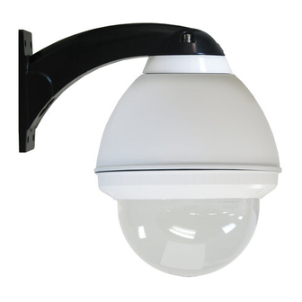
Outdoor PTZ Fusion Dome Mount
Installation and Operation Instructions for the following models:
FDW7C12N-3
IP Network Ready 7" Outdoor FusionDome PTZ Camera System with
36x zoom Day/Night camera, wall mount, MPEG-4/ MJPEG video
compression, full D1. Clear dome, with 12VDC input, heater/blower
FDP7C12N-3
IP Network Ready 7" Outdoor FusionDome PTZ Camera System with
36x zoom Day/Night camera, pendent mount, MPEG-4/ MJPEG video
compression, full D1. Clear dome, with 12VDC input, heater/blower
FDW7C12S-3
(Analog Version) 7" Outdoor FusionDome PTZ Camera System with
36x zoom Day/Night camera, wall mount, MPEG-4/ MJPEG video
compression, full D1. Clear dome, with 12VDC input, heater/blower
FDP7C12S-3
(Analog Version) 7" Outdoor FusionDome PTZ Camera System with
36x zoom Day/Night camera, pendent mount, MPEG-4/ MJPEG video
compression, full D1. Clear dome, with 12VDC input, heater/blower
B e fo r e a t t e m p t i n g t o c o n n e c t o r o p e r a t e t h i s p r o d u c t , p l e a s e r e a d t h e s e
i n s t r u c t i o n s c o m p l e t e l y. To b e u s e d w i t h t h e 8 1 - I N 5 4 0 9 I n s t r u c t i o n M a n u a l .
81-IN5423
01-09-2009
Advertisement
Table of Contents

Related Manuals for Moog Videolarm SView FDP7C12N-9


Summary of Contents for Moog Videolarm SView FDP7C12N-9
- Page 1 F D W 7 C 1 2 N - 3 Outdoor PTZ Fusion Dome Mount Installation and Operation Instructions for the following models: FDW7C12N-3 IP Network Ready 7” Outdoor FusionDome PTZ Camera System with 36x zoom Day/Night camera, wall mount, MPEG-4/ MJPEG video compression, full D1.
-
Page 2: Important Safeguards
IMPORTANT SAFEGUARDS Read these instructions. Keep these instructions. Heed all warnings Follow all instructions. Do not use this apparatus near water. Clean only with damp cloth. Do not block any of the ventilation openings. Install in accordance with the manufacturers instructions. Cable Runs- All cable runs must be within permissible distance. -
Page 3: Limited Warranty
1. NOTIFICATIONOF CLAIMS: WARRANTYSERVICE: If Purchaser believes that the Product is defective in material or workmanship, then written notice with an explanation of the claim shall be given promptly by Purchaser to Videolarm but all claims for warranty service must be made within the warranty period. -
Page 4: Electrical Specifications
Electrical Specifications Power 12VDC Class 2 Only 12 VDC 50 WATTS Accessories: Heater: 20 Watts, Blower: 2 Watt Camera Power: (See Camera Specifications): 28 Watts Max Tools Required: .100” Flat Head Screwdriver Phillips Head Screwdriver English 12VDC 50 Vatios De Accesorios: Calentador: 20 Watts, Blower: 2 Vatio Energía De la Cámara fotográfica De : (Véase Las Especificaciones De la Cámara fotográfica): 28 Vatios... - Page 5 Securely mount unit to wall or to appropriate adapter bracket. • Monte con seguridad la unidad a la pared o al soporte apropiado del adaptador. • Montez solidement l'unité au mur ou à la parenthèse appropriée d'adapteur. • Bringen Sie sicher Maßeinheit zur Wand oder zum passenden Adapterhaltewinkel an.
- Page 6 Securely mount bracket to wall. Pull wiring through bracket and position grommet as shown. • Con seguridad soporte del montaje a emparedar. Tire del cableado a través del soporte y del ojal de la posición según lo demostrado. • Solidement parenthèse de bâti à murer. Tirez le câblage par la parenthèse et le canon isolant de position comme montré.
- Page 7 Loop the lanyard over the set screw to temporarily hold housing. • Coloque el acollador sobre el tornillo de presión para celebrar temporalmente la cubierta. • Faites une boucle la lanière au-dessus de la vis de réglage pour tenir temporairement le logement. •...
- Page 8 Power and Control Inputs (Outside of Housing) RJ45 (Large) POWER (Small) POWER Make the appropriate male and female connections. Indoor model does not include pre-run cables. • Haga las conexiones masculinas y femeninas apropiadas. El modelo de interior no incluye pre-funciona los cables. •...
- Page 9 Remove Pan/Tilt from shipping carton. Install in base bracket in housing. • Quite Pan/Tilt del cartón del envío. Instale en soporte bajo en la cubierta. • Enlevez Pan/Tilt du carton d'expédition. Installez dans la parenthèse basse dans le logement. • Entfernen Sie Pan/Tilt vom Verschiffenkarton. Bringen Sie in niedrigen Haltewinkel im Gehäuse an.
- Page 10 Fasten down the dome with a Phillips screwdriver. • Sujete abajo de la bóveda con un destornillador Phillips. • Attachez en bas du dôme avec un tournevis Phillips. • Befestigen Sie sich hinunter die Haube mit einem Kreuzkopfschraubenzieher. • Prenda abaixo a abóbada com uma chave de fenda Phillips.
-
Page 11: Replacement Parts List
Replacement Parts List 1 1 1 Part Number RPFD7501 FD7T FD7C RPFD703 RPFD07/12 RPFD080 RPFD060 RP40PCCM0D01 RPFD040 RPFD709 RPFD2612 WM10 SD0170 SD0180 SD0160 RPPKE1100 RPPKH2090 RPPKH2071 RPPKE1125 RPTRN02 RPVL2857 RP76VL385A RP96PSGK08 RPVL3097 RP76P0F060E RP7OP14015 FDW7C12N-9 FDP7C12N-9 FDW7C12S-9 FDP7C12S-9 Description LOWER TRIM RING TINTED REPLACEMENT CAPSULE CLEAR REPLACEMENT CAPSULE DOME CLAMPING BRACKET... - Page 12 S - V I E W PA N / T I LT Analog & IP Installation and Operation Supplement: B e fo r e a t t e m p t i n g t o c o n n e c t o r o p e r a t e t h i s p r o d u c t , 81-IN5409 p l e a s e r e a d t h e s e i n s t r u c t i o n s c o m p l e t e l y.
- Page 13 Electrical Specifications Class 2 Power Supply Only MODELS: 24 VAC S-view: Analog 13 WATTS S-view: IP 28 WATTS MODELS: 12VDC English S-view: Analog 13 WATTS S-view: IP 20 WATTS Fuente De Alimentación De la Clase 2 Solamente. MODELOS: 24 VAC S-vista: Análogo 13 VATIOS S-vista: IP...
- Page 14 Remove Pan/Tilt from shipping carton. Install in base bracket in housing. • Quite Pan/Tilt del cartón del envío. Instale en soporte bajo en la cubierta. • Enlevez Pan/Tilt du carton d'expédition. Installez dans la parenthèse basse dans le logement. • Entfernen Sie Pan/Tilt vom Verschiffenkarton. Bringen Sie in niedrigen Haltewinkel im Gehäuse an.
- Page 15 • Al usar el regulador de Videolarm; para incorporar el menú; seleccione la cámara fotográfica que usted desea contro- lar. • En utilisant le contrôleur de Videolarm ; pour écrire le menu ; choisissez l'appareil-photo que vous souhaitez commander. • Wenn Videolarm Steuerpult verwendet wird; das Menü...
- Page 16 (IP) IP INSTRUCTIONS: The factory default IP address is : 192.168.0.200. • INSTRUCCIONES DEL IP: El IP address del defecto de la fábrica es: 192.168.0.200. • INSTRUCTIONS D'IP : Le IP address de défaut d'usine est : 192.168.0.200. • IP ANWEISUNGEN: Das Fabrikrückstellung IP address ist: 192.168.0.200.
- Page 17 Use Up & Down control on the controller to navigate through the menu. Pan left and right are used to enter sub menus. • Utilice para arriba y abajo controle en el regulador para navegar a través del menú. La cacerola a la izquierda e a la derecha se utiliza para incorporar menús secundarios.
-
Page 18: Camera Menu
When activated this will display camera’s address on the monitor. • Cuando está activado esto exhibirá la dirección de la cámara fotográfica en el monitor. • Quand activé ceci montrera l'adresse de l'appareil- photo sur le moniteur. • Wenn Sie diesem aktiviert werden, zeigt Adresse der Kamera auf dem Monitor an. - Page 19 CAMERA / STABILIZATION Camera sub menu includes, image stabilization, day/night mode, shutter, backlight, AGC and digital zoom. Image stabilization is not a feature of all cameras. • El menú secundario de la cámara fotográfica incluye, estabilización de la imagen, modo de day/night, obturador, contraluz, AGC y zumbido digital. La estabilización de la imagen no es una característica de todas las cámaras fotográficas.
-
Page 20: System Info
Llimit will “turn off” menu and allow you to position camera for left limit of zone. • Voluntad de Llimit "dar vuelta apagado" al menú y permitir que usted coloque la cámara fotográfica para el límite izquierdo de la zona. •... - Page 21 Allow user to set dwell time for each stored preset. If presets have not been saved the dwell time for that preset will be displayed as “”. • Permita que el usuario fije el tiempo de detención para cada uno almacenada preestablecen.
-
Page 22: Other Features
1, 2, 3... To set a manually controlled pattern by joystick set Preset 80 (80,#, • Para fijar un patrón manualmente controlado por el sistema de la palanca de mando preestablezca 80 (80, #, • Pour placer un modèle manuellement commandé par l'ensemble de manche préréglez 80 (80, #, •... - Page 23 ADDRESS ADDRESS ADDRESS...
- Page 24 ADDRESS ADDRESS ADDRESS ADDRESS...
- Page 25 ADDRESS ADDRESS ADDRESS ADDRESS...
- Page 26 Replacement Parts List Part No. RP6039mm1.8 RPVL2314 RP40CASL385 RPVL2315 RP605007 RPVL2316 RPVL2318 RPVL2320 RP605011 RP73CAVKS454 RP92WSFN11 RP605009 RP605008 RP95FSSR06 RP95FSSR07 RP605010 RPVL2312R1 RP76V385T RP76V385P RPVL2317 RPVL2321 Description Motor (2) Hub Bracket Slip Ring Assembly (2) 20T 80 Pitch Pulley (2) Bearing 90T Pan Pulley 60T Tilt Pulley...
-
Page 27: Product Registration/Warranty
Product Registration/Warranty Thank you for choosing Videolarm. We value your patronage and are solely committed to providing you with only the highest quality products available with unmatched customer service levels that are second-to-none in the security industry. Should a problem arise, rest assure that Videolarm stands behind its products...
Need help?
Do you have a question about the SView FDP7C12N-9 and is the answer not in the manual?
Questions and answers