Table of Contents
Advertisement
Quick Links
Copyright
All rights are reserved. No part of this publication may be reproduced, transmitted,
transcribed, stored in a retrieval system or translated into any language or computer
language, in any form or by any means, electronic, mechanical, magnetic, optical, chemical,
manual or otherwise, without the prior written permission of the company. Brands and
product names are trademarks or registered trademarks of their respective companies.
The vendor makes no representations or warranties with respect to the contents herein and
especially disclaim any implied warranties of merchantability or fitness for any purpose.
Further the vendor reserves the right to revise this publication and to make changes to the
contents herein without obligation to notify any party beforehand. Duplication of this
publication, in part or in whole, is not allowed without first obtaining the vendor's approval
in writing.
Trademark
All the trademarks or brands in this document are registered by their respective owner.
Disclaimer
We make no warranty of any kind with regard to the content of this user's manual. The
content is subject to change without notice and we will not be responsible for any mistakes
found in this user's manual. All the brand and product names are trademarks of their
respective companies.
FCC Compliance Statement
This equipment has been tested and found to comply with the limits of a Class B digital
device, pursuant to Part 15 of the FCC Rules. These limits are designed to provide reasonable
protection against harmful interference in a residential installation. This equipment
generates, uses and can radiate radio frequency energy and, if not installed and used in
accordance with the instructions, may cause harmful interference to radio communications.
Operation of this equipment in a residential area is likely to cause harmful interference in
which case the user will be required to correct the interference at his own expense. However,
there is no guarantee that interference will not occur in a particular installation.
CE Mark
The device is in accordance with 89/336 ECC-ENC Directive.
Ver: EG101
nForce 650i Ultra
Advertisement
Table of Contents

Related Manuals for Albatron NForce 650i Ultra


Summary of Contents for Albatron NForce 650i Ultra
-
Page 1: Fcc Compliance Statement
650i Ultra Copyright All rights are reserved. No part of this publication may be reproduced, transmitted, transcribed, stored in a retrieval system or translated into any language or computer language, in any form or by any means, electronic, mechanical, magnetic, optical, chemical, manual or otherwise, without the prior written permission of the company. - Page 2 Mainboard nForce 650i Ultra nForce 650i Ultra nVIDIA nForce 650i Ultra MCPs ® Support Socket 775 ® Intel Core 2 Extreme/ Core 2 Quad/ Core 2 Duo/ ® Pentium Extreme Edition/ ® Pentium Processors User Manual Dimensions (ATX form-factor): 244mm x 305mm ( W x L ) Operating System: ®...
-
Page 3: Packing List
Mainboard nForce 650i Ultra Things You Have To Know The images and pictures in this manual are for reference only and may vary from the product you received depending on specific hardware models, third party components and software versions. This mainboard contains very delicate IC chips. Always use a grounded wrist strap when working with the system. -
Page 4: Table Of Contents
CHAPTER 1. GETTING STARTED ............ 1 ....................... 1 NTRODUCTION ....................... 2 PECIFICATION ....................5 ONFIGURATION Layout of nForce 650i Ultra ................5 ................... 6 ARDWARE NSTALLATION CPU Processor Installation................6 Memory Installation: DIMM0/1/2/3..............7 Back Panel Configuration................9 Connectors..................... 11 Front Panel Headers: FRONTPNL.............. -
Page 5: Chapter 1. Getting Started
PCI expansion cards are also allowed. The nForce 650i Ultra provides one floppy disk drive connector that can be used with 360KB/ 720KB/ 1.2MB/ 1.44MB/ 2.88MB drives. There is also one IDE connector for connecting two IDE hard drives supporting Ultra ATA 33/66/100/133. -
Page 6: Specification
Mainboard nForce 650i Ultra Specification Support Socket 775 ® ® Support Intel Core 2 Extreme/ Core 2 Quad/ Core 2 Duo/ Pentium Extreme ® Edition/ Pentium Processors Support Hyper-Threading Technology Support 1066 MHz/ 800 MHz/ 533 MHz FSB (Front Side Bus) Frequencies Chipset ®... -
Page 7: Fdd Connector
Mainboard nForce 650i Ultra 2. Two PCI-E x1 slots: supports up to x1 mode with 250 MB/s one-way bandwidth Three PCI interface slots for expansion cards FDD Connector Supports one FDD connector to set up to two floppy disk drives Supports 360KB/ 720KB/ 1.2MB/ 1.44MB/ 2.88MB... -
Page 8: Flash Memory
Mainboard nForce 650i Ultra Support APM 1.2 Support ACPI 2.0 power management Green Function Supports ACPI (Advanced Configuration and Power Interface) Supports Phoenix-Award™ BIOS power management function Supports S0 (normal), S1 (power on suspend), S3 (suspend to RAM), S4 (suspend to disk –... -
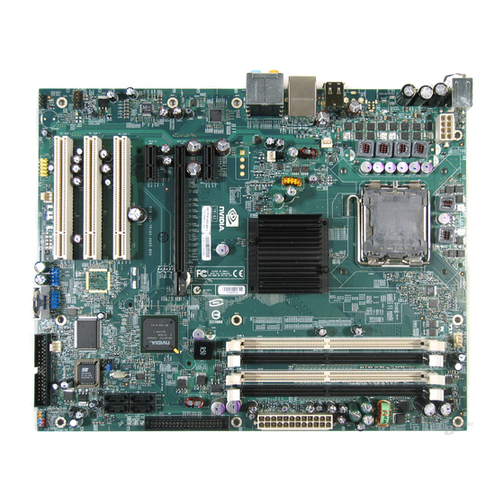
Page 9: Configuration
Mainboard nForce 650i Ultra Configuration Layout of nForce 650i Ultra... -
Page 10: Hardware Installation
Mainboard nForce 650i Ultra Hardware Installation This section will assist you in quickly installing your system hardware. Wear a wrist ground strap before handling components. Electrostatic discharge may damage the system’s components. CPU Processor Installation ® ® These mainboards support Intel... -
Page 11: Memory Installation: Dimm0/1/2/3
C55 FAN Memory Installation: DIMM0/1/2/3 The nForce 650i Ultra mainboard provides four DIMM (Dual In-Line Memory Modules) sockets which allow you to install 240-pin, unbuffered non-ECC, DDRII 800/ 667/ 533 SDRAMs. It also supports Dual Channel Technology and allow you to install a total memory capacity of 8 GB. - Page 12 Mainboard nForce 650i Ultra How to enable Dual-Channel DDRII: The mainboard provides Dual-Channel functionality for the four DIMM sockets. Enabling Dual-Channel will significantly increase your data access rate than the before. DIMM0 and DIMM1 share one channel, and DIMM2 and DIMM3 share another channel.
-
Page 13: Back Panel Configuration
Mainboard nForce 650i Ultra Repeat steps 1, 2 & 3 for the remaining RAM modules. * The pictures above are for reference only. Your actual installation may vary slightly from the pictures. Back Panel Configuration PS/2 Mouse & PS/2 Keyboard Ports: KB/MS These mainboards provide a standard PS/2 mouse port and a PS/2 keyboard port. - Page 14 Mainboard nForce 650i Ultra Audio Ports: SOUND This mainboard provides six HD Audio ports for 8/6/4/2 channel playback capability. With jack sensing, auto detecting and adjusting, the device will make it easier to Plug and Play for you. Line-In (blue) This port is for audio input and connects to external audio devices such as CD player, tape player or other audio devices when the 8/6/4/2 channel audio effects driver is enabled.
-
Page 15: Connectors
Mainboard nForce 650i Ultra Connectors Floppy Disk Drive Connector: FLOPPY The mainboard provides a standard floppy disk drive connector (FDD) that supports 360KB/ 720KB/ 1.2MB/ 1.44MB/ 2.88 MB floppy disk drives using a FDD ribbon cable. Hard Disk Drive Connectors: IDE The mainboard provides one IDE connector that supports Ultra ATA 33/66/100/133 IDE devices. -
Page 16: Front Panel Headers: Frontpnl
Mainboard nForce 650i Ultra Front Panel Headers: FRONTPNL FRONTPNL Assignment Function Assignment Function HD_PWR (+) HDR_BLNK_GRN Hard Disk LED Front Panel Light (HD_LED) (PWRLED) HAD# HDR_BLNK_YEL SWITCH_ON# Reset Switch Power Switch (RESET) (PWRSW) FP_RESET# Hard Disk LED Header (Orange): HD_LED If your case front panel has a hard drive LED cable, attach it to this header. -
Page 17: Headers & Jumpers
Mainboard nForce 650i Ultra Headers & Jumpers Case Open Warning Header: CASE OPEN This header is used to warn the user when the computer case has been previously opened. Please connect the header with a cable to your case directly. (Make sure that your computer case provides this “case open”... -
Page 18: Audio Configuration
Mainboard nForce 650i Ultra Clear CMOS Jumper: CLR_CMOS The “Clear CMOS” function is used when you are unable boot your system and need to reset the BIOS settings (CMOS settings) back to the manufacturer’s original settings. This is also a way to reset the system password if you have forgotten it. -
Page 19: Slots
Mainboard nForce 650i Ultra Slots PCI-Express x16 Interface slot: PCIE x16 The mainboard allows you to install a graphics card, which the PCI-Express x16 interface, supporting one-way bandwidth up to 4 GB/s, is compatible to this PCIE x16 slot. PCI-Express x1 Interface slots: PCIE x1_1/ PCIE x1_2 The PCIE x1_1/ PCIE x1_2 slots are the PCI-Express x1 interface slots which can be supported up to x1 mode. -
Page 20: Power Supply Attachments
Mainboard nForce 650i Ultra Power Supply Attachments ATX Power Connector: ATXPWR, ATX12V This mainboard provides two ATX power connectors, a 24-pin ATXPWR connector and an 8-pin ATX12V connector. You must use a power supply that has both of these connectors and both connectors must be attached before the system is powered on. -
Page 21: Chapter 2. Bios Setup
Mainboard nForce 650i Ultra Chapter 2. BIOS Setup Introduction This section describes PHOENIX-AWARD™ BIOS Setup program which resides in the BIOS firmware. The Setup program allows users to modify the basic system configuration. The configuration information is then saved to CMOS RAM where the data is sustained by battery after power-down. -
Page 22: Main Menu
Mainboard nForce 650i Ultra Main Menu Standard CMOS Features Include all the adjustable items in standard compatible BIOS. Advanced BIOS Features Include all the adjustable items of Award special enhanced features. Advanced Chipset Features Include all the adjustable items of chipset special features. - Page 23 Mainboard nForce 650i Ultra PnP/PCI Configurations Include all configurations of PCI and PnP ISA resources. System Monitor It is for monitoring the system status such as temperature, voltage, and fan speeds. Load Defaults It can load the preset system parameter values to set the system in its stable performance configurations.
-
Page 24: Chapter 3: Software Setup
Mainboard nForce 650i Ultra Chapter 3: Software Setup Software List Category Platform ® Windows Vista/ XP/ 2000 NVIDIA Chipset INF ® Windows Vista/ XP/ 2000 Realtek Audio Driver ® Windows XP/ 2000 Microsoft DirectX9.0c Attention You don’t need to install the driver for USB 2.0 version if you are using Windows®... - Page 25 Mainboard nForce 650i Ultra Windows Vista Driver ® Windows XP (64bit) Driver ® Attention ® Before you install the Realtek Audio Driver on Windows ® (64bit) operating system, please go to the Microsoft website to install the update for enabling HD Audio.
- Page 26 Mainboard nForce 650i Ultra Windows XP (32bit) Driver ® Windows 2000 Driver ®...
- Page 27 Mainboard nForce 650i Ultra NVIDIA Chipset INF – It provides all drivers for the functions which built in both the Northbridge/ Southbridge. Realtek Audio Driver – It provides the driver of Realtek HD Audio CODEC. Microsoft DirectX 9.0c – It provides the software of Microsoft DirectX9.0c.
-
Page 28: Chapter 4: Troubleshooting
Mainboard nForce 650i Ultra Chapter 4: Troubleshooting Problem 1: No power to the system. Power light does not illuminate. Fan inside power supply does not turn on. Indicator lights on keyboard are not lit. Causes: 1. Power cable is unplugged. - Page 29 Mainboard nForce 650i Ultra Problem 4: System only boots from the CD-ROM. The hard disk can be read and applications can be used but booting from the hard disk is impossible. Causes: Hard Disk boot sector has been corrupted. Solutions: Back up data and applications files. Reformat the hard drive. Re-install applications and data using backup disks.
- Page 30 Mainboard nForce 650i Ultra Problem 10: Keyboard failure. Causes: Keyboard is disconnected. Solutions: Reconnect keyboard. Replace keyboard if you continue to experience problems. Problem 11: No color on screen. Causes: 1. Faulty Monitor. 2. CMOS incorrectly set up. Solutions: 1. If possible, connect monitor to another system. If no color appears, replace monitor.
-
Page 31: Appendix I: 8/6/4/2 Channel Setup
Mainboard nForce 650i Ultra Appendix I: 8/6/4/2 Channel Setup Channels Setup for Windows Vista After entering the system, click the audio icon from the Windows Vista screen. When your audio device is plugged, the system will detect it and show the “Speakers” tab automatically. - Page 32 Mainboard nForce 650i Ultra Channels Setup for Windows XP/ 2000 After into the system, click the audio icon from the Windows XP screen. Click “Audio I/O” button, you can see the screen like the picture below. You can choose 2, 4, 6 or 8 channels by your speakers.
-
Page 33: Appendix Ii: Raid Setup
Mainboard nForce 650i Ultra Appendix II: RAID Setup Introduction to RAID RAID (Redundant Array of Independent Disks) technology is a sophisticated disk management system that manages multiple disk drives. It enhances I/O performance and provides redundancy in order to prevent the loss of data in case of individual disk failure. The RAID facility on this board provides RAID 0, RAID 1, RAID 0+1, RAID JBOD, and RAID 5. - Page 34 Mainboard nForce 650i Ultra Before you create a RAID Array Before you configure your RAID Array, you have to enable the “RAID” option in the BIOS Setup Utility. Integrated Peripherals >> RAID Config >> RAID Enable >> Save & Exit Setup When the screen below displays, press <Delete>...
- Page 35 Mainboard nForce 650i Ultra After entering the sub-menu, arrow down to the "RAID Config"item. Press <Enter>. Enable the “RAID Enable” item and then select the SATA ports with disks that you want to use for RAID. Press <Esc> to exit this screen.
- Page 36 Mainboard nForce 650i Ultra At the main screen arrow over to the "Save & Exit Setup" item. Press <Enter>. Press <Y>, and then press <Enter> to finish the setup. NVIDIA RAID Setup Utility Configuration The NVIDIA RAID Setup Utility is used to configure RAID disk management into your hard...
- Page 37 Mainboard nForce 650i Ultra When the system boots up during the POST (Power-On Self Test), you will be given an opportunity to enter the NVIDIA RAID Setup Utility when the screen prompts you with the following message. “Press <F10> to enter RAID setup utility…”...
- Page 38 Mainboard nForce 650i Ultra Attention The “Port” and “Disk Model”, shown on these screens represent the disk drives installed on the PATA or SATA connectors and are sample data only. The actual data that displays on your screen will likely vary.
- Page 39 Mainboard nForce 650i Ultra Stripe Block Stripe block size will directly affect performance when data is written to or read by your system. • • • • • • 128K • Optimal * This item is not available for RAID 1 and JBOD arrays.
-
Page 40: Creating A New Array
Mainboard nForce 650i Ultra Creating a New Array The screen you will see upon initial configuration is the “Define a New Array” screen. <Tab> over to the “RAID Mode” item and press <Enter>. According to your configuration requirements, select “Mirrored” (RAID 1), “Striped” (RAID 0), “Striped Mirror“ (RAID 0+1), “Spanned”... - Page 41 Mainboard nForce 650i Ultra <Tab> over to the “Free Disks” selection box, and use the up/down arrow keys to select disks for your RAID array. Use the right-arrow key to move selected disks to the “Array Disks” section (the selected drive will be highlighted). You can use the left-arrow key to...
- Page 42 Mainboard nForce 650i Ultra After all of the options are properly configured, press <F7>. A confirmation box will display as shown below. Hit <Y> to continue the RAID array creation. An alert box will appear as shown below. Press <Y> to clear the Master Boot Record and...
- Page 43 Mainboard nForce 650i Ultra In the next page, you will see the “Array List” screen as shown below. You can press <Enter> to view the details. The “Array Detail” screen provides you all the information of the RAID array you created.
- Page 44 Mainboard nForce 650i Ultra When you see the screen below, please confirm the information about the RAID arrays you have created. If you select a RAID Mode with wrong hard disk numbers… ■ For example, if you select “Mirrored” configure four hard disks into your array disks, and...
- Page 45 Mainboard nForce 650i Ultra Then you will see an alert box to notify you that you selected an invalid number of disks. In a mirrored array, you can only configure two disks at one time. You must press <Enter> to go back to the main screen to reconfigure your options again.
- Page 46 Mainboard nForce 650i Ultra Deleting Array If you want to delete an existing array, go to the “Array Detail screen as below. Press <D>. An alert box will display for your confirmation to delete the array. Press <Y> to delete.
- Page 47 Mainboard nForce 650i Ultra After the array is deleted successfully, you will return to the main screen where you can re-create a new array as shown below.
- Page 48 Mainboard nForce 650i Ultra Configuring a Bootable Array Use the up/down arrow keys to select an array. Then press <B> to specify the selected array as a bootable array. You will see a special symbol, “√”, marked in the Boot item of the highlighted array.
- Page 49 SATA connectors, and your RAID arrays have already been configured using the NVIDIA RAID Setup Utility (NVIDIA RAID Setup Utility Configuration section). Download the NVIDIA RAID driver from the Albatron website. Go to the Albatron website: http://www.albatron.com.tw Move your mouse pointer to the “Product Info”...
- Page 50 Mainboard nForce 650i Ultra Select your mainboard. The example used below is “NF 680i SLI” mainboard. Click “Driver” as shown below on the left panel. Click the download icon to download the NVIDIA RAID driver (You should download the RAID driver according to your operating system).
- Page 51 Mainboard nForce 650i Ultra Press the “Save” button to download the RAID zip file. You must unzip the file and save the files onto media that you can use on an existing storage device on your computer (e.g. floppy disk drive).
- Page 52 Mainboard nForce 650i Ultra Install Windows ® ® During the Windows XP installation, a “Windows Setup” screen will prompt you with “Press F6 if you need to install third party SCSI or RAID driver”. Press <F6>. Press <s> when setup asks if you want to specify an additional device.
- Page 53 Mainboard nForce 650i Ultra Insert the media which includes the “RAID Driver” into your computer. Press <Enter> to locate the appropriate OS device driver. You will install two drivers. Select the “NVIDIA RAID CLASS DRIVER (required)” and press <Enter> to locate this...
- Page 54 Mainboard nForce 650i Ultra When you see the screen shown as below again, press <s> to download the second RAID driver. Select the “NVIDIA nForce Storage Controller (required)” and also, press <Enter>.
- Page 55 Mainboard nForce 650i Ultra ® You have finished RAID drivers installation. Press <Enter> to continue the Windows setup process. Follow the setup instructions and select the partition and file system where you want to install the operating system files. ®...
- Page 56 SATA connectors, and your RAID arrays have already been configured using the NVIDIA RAID Setup Utility (NVIDIA RAID Setup Utility Configuration section). Download the NVIDIA RAID driver from the Albatron website. Go to the Albatron website: http://www.albatron.com.tw Move your mouse pointer to the “Product Info”...
- Page 57 Mainboard nForce 650i Ultra Select your mainboard. The example used below is “NF 680i SLI” mainboard. Click “Driver” as shown below on the left panel. Click the download icon to download the NVIDIA RAID driver (You should download the RAID driver according to the operating...
- Page 58 Mainboard nForce 650i Ultra Press the “Save” button to download the RAID zip file. You must unzip the file and save the files to media that you can use on an existing storage device on your computer (floppy disk drive, or USB Flash Drive).
- Page 59 Mainboard nForce 650i Ultra Install Windows Vista ® ® During a Windows Vista installation, there will be an item “Load Driver”. Click on it and then insert the media containing the RAID Driver files into your computer. You will install two drivers.
- Page 60 Mainboard nForce 650i Ultra Select the media which includes the RAID Drivers. The example here is “floppy disk drive”. Make sure you have inserted the floppy disk including the RAID Drivers. Select “Floppy Disk Drive(A:)”. Click “OK” to load the RAID...
- Page 61 Mainboard nForce 650i Ultra Select the “NVIDIA nForce RAID Controller” and click “Next” to locate this driver. Please wait until finished. When you go back to the screen shown as below, click “Load Driver” again to download the second RAID driver.
- Page 62 Mainboard nForce 650i Ultra Click on “Browse” to browse into the folders of the media to locate the folder with the files. Select the media which includes the RAID Drivers.
- Page 63 Mainboard nForce 650i Ultra Select “Floppy Disk Drive(A:)” and click “OK” to load the RAID Drivers. The system will rescan for the drivers automatically. 10. Select the “NVIDIA nForce Serial ATA Controller” and click “Next” to continue. Please wait until finished.
- Page 64 Mainboard nForce 650i Ultra 11. You will return to the “Install Windows” screen to continue with the installation. Follow the setup instructions and select the partition where you want to install the operating system files. ® 12. After setup examines your disks, it will copy files to the Windows Vista installation folders and restart the system.
- Page 65 Mainboard nForce 650i Ultra Rebuilding a RAID Mirrored Array This section will illustrate how to replace a failed drive with a new one, and rebuild the array to restore lost data on the newly installed drive. Rebuilding only applies to fault-tolerant arrays which are RAID 1, RAID 0+1, and RAID 5 arrays.
- Page 66 Mainboard nForce 650i Ultra You should see the existing RAID array on your system. Press <R> to rebuild the array. The next screen will display as below. Use up/down arrow keys to select a free disk. Press <A> to continue.
- Page 67 Mainboard nForce 650i Ultra An alert box will display for your confirmation to rebuild array. Press <Enter> to go to the next step. A confirmation box will display as shown below. Hit <Y> to continue rebuilding the RAID array.
- Page 68 Mainboard nForce 650i Ultra You have successfully finished the setup of rebuilding an array in the “NVIDIA RAID Setup Utility”. Press <Ctrl-X> to restart your computer. 10. During the boot process, you will see the screen below. Confirm the “Rebuild” information...
- Page 69 Mainboard nForce 650i Ultra 11. The Rebuild process is automatic. You can check of the Rebuild in the following steps. Go to to “Start → All Programs → NVIDIA Corporation → NVIDIA Control Panel → Storage” under Windows. 12. A notification box will display to notify you rebuilding the array is started. Rebuilding the...
- Page 70 Mainboard nForce 650i Ultra 13. When the rebuilding is finished, make sure the “Status” item for your Rebuild Array shows “Healthy”. You have now successfully rebuilt the RAID array.
Need help?
Do you have a question about the NForce 650i Ultra and is the answer not in the manual?
Questions and answers