Table of Contents
Advertisement
KM61S-AM2
Copyright
All rights are reserved. No part of this publication may be reproduced, transmitted, transcribed,
stored in a retrieval system or translated into any language or computer language, in any form
or by any means, electronic, mechanical, magnetic, optical, chemical, manual or otherwise,
without the prior written permission of the company. Brands and product names are trademarks
or registered trademarks of their respective companies.
The vendor makes no representations or warranties with respect to the contents herein and
especially disclaim any implied warranties of merchantability or fitness for any purpose. Further
the vendor reserves the right to revise this publication and to make changes to the contents
herein without obligation to notify any party beforehand. Duplication of this publication, in part or
in whole, is not allowed without first obtaining the vendor's approval in writing.
Trademark
All the trademarks or brands in this document are registered by their respective owner.
Disclaimer
We make no warranty of any kind with regard to the content of this user's manual. The content
is subject to change without notice and we will not be responsible for any mistakes found in this
user's manual. All the brand and product names are trademarks of their respective companies.
FCC Compliance Statement
This equipment has been tested and found to comply with the limits of a Class B digital device,
pursuant to Part 15 of the FCC Rules. These limits are designed to provide reasonable
protection against harmful interference in a residential installation. This equipment generates,
uses and can radiate radio frequency energy and, if not installed and used in accordance with
the instructions, may cause harmful interference to radio communications. Operation of this
equipment in a residential area is likely to cause harmful interference in which case the user will
be required to correct the interference at his own expense. However, there is no guarantee that
interference will not occur in a particular installation.
CE Mark
The device is in accordance with 89/336 ECC-ENC Directive.
Ver: EG101
Advertisement
Table of Contents

Related Manuals for Albatron KM61S-AM2


Summary of Contents for Albatron KM61S-AM2
-
Page 1: Fcc Compliance Statement
KM61S-AM2 Copyright All rights are reserved. No part of this publication may be reproduced, transmitted, transcribed, stored in a retrieval system or translated into any language or computer language, in any form or by any means, electronic, mechanical, magnetic, optical, chemical, manual or otherwise, without the prior written permission of the company. - Page 2 KM61S-AM2 nVIDIA MCP61S ® Supports Socket AM2 Athlon 64 FX/ Athlon 64 x2 Dual-Core/ ® Athlon x2 Dual-Core/ Athlon 64/ Sempron Processor User Manual Dimensions (Micro-ATX Form-Factor): 205 mm x 244 mm ( W x L ) Operating System: Windows® 2000/ XP...
-
Page 3: Packing List
Do not touch any IC chip, lead, connector or other components. Always unplug the AC power when you install or remove any device on the mainboard or when confuguring pins and switches. Packing List KM61S-AM2 mainboard IDE Cable I/O Bracket Serial ATA Cable Mainboard Setup Driver &... -
Page 4: Table Of Contents
Table of Contents CHAPTER 1. GETTING STARTED ............ 1 ....................... 1 NTRODUCTION ....................... 2 PECIFICATION ....................5 ONFIGURATION Layout of KM61S-AM2 .................. 5 ................... 6 ARDWARE NSTALLATION CPU Processor Installation................6 Memory Installation: DIMMA1/B1 ..............7 Back Panel Configuration................9 Connectors..................... 11 Front Panel Headers: JPANEL1 .............. -
Page 5: Chapter 1. Getting Started
Sony/Philips Digital Interfaces (SPDIF) output function (Optional). The KM61S-AM2 also comes with an onboard 10/100 Mbps Ethernet LAN PHY chip. There is a LAN port on the back panel of your case that you can directly plug into an internet cable. -
Page 6: Specification
Mainboard KM61S-AM2 Specification CPU: Supports Socket AM2 Supports AMD Athlon 64 FX/ Athlon 64 x2 Dual-Core/ Athlon x2 Dual-Core/ Athlon 64/ Sempron Processor Supports Hyper-Transport Link Technology Supports 1000 MHz(2000MT/s)FSB(Front Side Bus)Frequencies Chipset: ® ® Chipset – nVIDIA MCP61S(nVIDIA GeForce 6100 nForce 405)... -
Page 7: Universal Serial Bus
Mainboard KM61S-AM2 Supports Ultra ATA 133/ 100/ 66/ 33 Supports high capacity hard disk drives Serial ATA II Connector: Two SATA II connectors that support up to two SATA II HDD Supports SATA 2.0 specification which provides 3 Gbps transmit rate... -
Page 8: Flash Memory
Mainboard KM61S-AM2 BIOS: Phoenix-Award™ BIOS Supports APM 1.2 Supports ACPI 2.0 power management Green Function: Supports Phoenix-Award™ BIOS power management function Supports system-wake-from-power-saving-mode by keyboard or mouse touching Shadow RAM: Integrated memory controller provides shadow RAM functionality and supports ROM... -
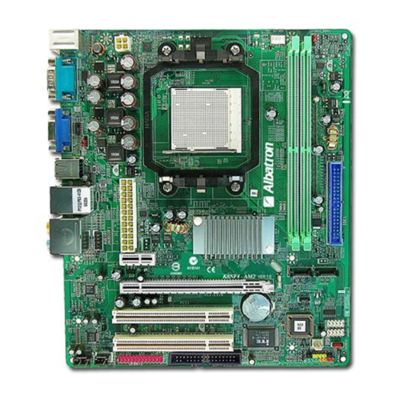
Page 9: Configuration
Mainboard KM61S-AM2 Configuration Layout of KM61S-AM2... -
Page 10: Hardware Installation
Mainboard KM61S-AM2 Hardware Installation This section will assist you in quickly installing your system hardware. Wear a wrist ground strap before handling components. Electrostatic discharge may damage your system components. CPU Processor Installation This mainboard supports AMD Athlon 64 FX/ Athlon... -
Page 11: Memory Installation: Dimma1/B1
Memory Installation: DIMMA1/B1 The KM61S-AM2 provides two DIMM (Dual In-Line Memory Modules) sockets with Dual Channel Technology supported. The sockets allow you to install 240-pin, non-ECC & unbuffered DDR II 800 (PC2-6400)/ DDR II 667 (PC2-5300)/ DDR II 533 (PC2-4300)/ DDR II 400 (PC2-3200) SDRAM, and support to install a total memory capacity of 2 GB. -
Page 12: Memory Installation Steps
Mainboard KM61S-AM2 How to Enable Dual-Channel functionality: This mainboard provides Dual-Channel functionality for the two DIMM sockets. Enabling Dual-Channel can significantly increase your data access rates. DIMMA1 and DIMMB1 share one channel. For enabling Dual-Channel, you have to install two memories in the DIMM sockets at the same time;... -
Page 13: Back Panel Configuration
Mainboard KM61S-AM2 Repeat steps 1, 2 & 3 for the remaining RAM modules. * The pictures above are for reference only. Your actual installation may vary slightly from the pictures. Back Panel Configuration PS/2 Mouse & PS/2 Keyboard Ports: JKBMS1 This mainboard provides a standard PS/2 mouse port and a PS/2 keyboard port on the back panel of your case. - Page 14 Mainboard KM61S-AM2 The VGA (D-SUB) Connector: JVGA1 Your VGA monitor can attach directly to this VGA connector. USB Ports/LAN Port: JUSB1, JUSBLAN1 There are four onboard USB 2.0/ 1.1 ports on the back panel. These USB ports are used to attach with USB devices, such as keyboard, mice and other USB supported devices.
-
Page 15: Connectors
Mainboard KM61S-AM2 Rear Surround-out(black) This port is only functional for the output of the surround sound rear speakers when the 8/6/4/2 channel audio driver is installed and enabled. This mainboard supports multi-channel audio system which allows you to transform your 2 speaker audio system into 8/ 6/ 4 speaker audio system. -
Page 16: Front Panel Headers: Jpanel1
Mainboard KM61S-AM2 Attention The FDD/ IDE cable is designed and should be attached with a specific direction. One edge of the cable will usually in color such as red, to indicate that should line up with the header pin-1. Front Panel Headers: JPANEL1... -
Page 17: Headers & Jumpers
Mainboard KM61S-AM2 Reset button Header (Red): RST This header can be attached to a momentary SPST switch (reset button) cable on your case front panel. The switch is normally left open. When the switch closed, it will cause the mainboard to reset and run the POST (Power-On Self Test). - Page 18 Mainboard KM61S-AM2 Power Source Headers for USB Ports: JUSBV1/JUSBV2 USB devices attached to USB ports can awaken the system from sleep mode. In order to enable this functionality, you must adjust the jumper caps on JUSBV1/ JUSBV2 headers for +5V or +5V Standby mode.
- Page 19 Mainboard KM61S-AM2 Printer Interface Header: JPRNT1 This mainboard provides one JPRNT1 header for you connecting an additional printer connector on your case back panel. Attach the cable of printer connector (Optional) onto this header, and then you can use the printer connector connecting with a printer.
-
Page 20: Audio Configuration
Mainboard KM61S-AM2 Audio Configuration CD-ROM Audio-In Connector: JCDIN1 The CD-IN connector is used to attach an audio cable to audio devices such as CD-ROMs, DVD-ROMs etc. Assignment Left channel input Ground JCDIN1 Ground Right channel input SPDIF Header: JSPDIF_OUT1 S/PDIF is a recent audio transfer file format, which provides high quality audio using optical fiber and digital signals. -
Page 21: Slots
Mainboard KM61S-AM2 JAUDIOF1 Assignment Assignment Mic in Ground Mic Power Audio Power Right Line Out Ground Reserved Left Line Out 10 Ground Slots PCI-Express x1 Slot: PCI-E x1_1 This mainboard is able to install an expansion card which the PCI-Express x1 interface compatible such as network card, SCSI card, etc. -
Page 22: Power Supply Attachments
Mainboard KM61S-AM2 Power Supply Attachments ATX Power Connector: JATXPWR1, JATXPWR2 This mainboard provides two ATX power connectors, a 24-pin JATXPWR1 connector and a 4-pin JATXPWR2 connector. You must use a power supply that has both of these connectors and both connectors must be attached before the system is powered on. These power connectors support several power management functions such as the instant power-on function. -
Page 23: Chapter 2. Bios Setup
Mainboard KM61S-AM2 Chapter 2. BIOS Setup Introduction This section describes PHOENIX-AWARD™ BIOS Setup program which resides in the BIOS firmware. The Setup program allows users to modify the basic system configuration. The configuration information is then saved to CMOS RAM where the data is sustained by battery after power-down. -
Page 24: Main Menu
Mainboard KM61S-AM2 Main Menu Standard CMOS Features Include all the adjustable items in standard compatible BIOS. Advanced BIOS Features Include all the adjustable items of Award special enhanced features. Advanced Chipset Features Include all the adjustable items of chipset special features. - Page 25 Mainboard KM61S-AM2 Performance Booster Zone It is for you to specify settings for Frequency and Voltage Control, such as the CPU’s clock and frequency ratio. Load Optimized Defaults It can load the preset system parameter values to set the system in its best performance configurations.
-
Page 26: Chapter 3: Software Setup
Mainboard KM61S-AM2 Chapter 3: Software Setup Software List Category Platform ® Windows 2000 /XP Microsoft DirectX 9.0c ® Windows 2000 /XP nForce Chipset Driver ® Windows 2000 /XP nVIDIA Firewall ® Windows 2000 /XP Realtek Audio Driver ® Windows 2000 /XP... - Page 27 Mainboard KM61S-AM2 Microsoft DirectX 9.0c – provides the software of Microsoft DirectX 9.0c. nForce Chipset Driver – provides all the drivers needed for the chipset. nVIDIA Firewall – provides firewall to protect your system from hackers and viruses. Realtek Audio Driver – provides the driver for being able to input/output audio.
- Page 28 Mainboard KM61S-AM2 Adobe Acrobat Reader 6 – Installing the Adobe Acrobat Reader program, you can browse files with PDF styled. Trend PC-Cillin 2005 – It provides the software of Trend PC-Cillin 2005 (Anti-virus program). Drive Clone – It provides the software of Drive Clone which is used to back up or clone hard drives or partitions.
-
Page 29: Chapter 4: Troubleshooting
Mainboard KM61S-AM2 Chapter 4: Troubleshooting Problem 1: No power to the system. Power light does not illuminate. Fan inside power supply does not turn on. Indicator lights on keyboard are not lit. Causes: 1. Power cable is unplugged. 2. Defective power cable. - Page 30 Mainboard KM61S-AM2 Problem 4: System only boots from the CD-ROM. The hard disk can be read and applications can be used but booting from the hard disk is impossible. Causes: Hard Disk boot sector has been corrupted. Solutions: Back up data and applications files. Reformat the hard drive. Re-install applications and data using backup disks.
- Page 31 Mainboard KM61S-AM2 Problem 10: Keyboard failure. Causes: Keyboard is disconnected. Solutions: Reconnect keyboard. Replace keyboard if you continue to experience problems. Problem 11: No color on screen. Causes: 1. Faulty Monitor. 2. CMOS incorrectly set up. Solutions: 1. If possible, connect monitor to another system. If no color appears, replace monitor.
-
Page 32: Appendix I: 8/6/4/2 Channel Audio Effect Setup
Mainboard KM61S-AM2 Appendix I: 8/6/4/2 Channel Audio Effect Setup Channels Setup After into the system, click the audio icon from the Windows screen. Click “Audio I/O” button, you can see the screen like the picture below. You can choose 2, 4, 6 or 8 channels by your speakers. -
Page 33: Appendix Ii: Raid Setup
Mainboard KM61S-AM2 Appendix II: RAID Setup Introduction to RAID RAID (Redundant Array of Independent Disks) technology is a sophisticated disk management system that manages multiple disk drives. It enhances I/O performance and provides redundancy in order to prevent the loss of data in case of individual disk failure. The RAID facility on this board provides RAID 0, RAID 1, RAID 0+1, RAID JBOD, and RAID 5.
Need help?
Do you have a question about the KM61S-AM2 and is the answer not in the manual?
Questions and answers