Table of Contents
Advertisement
KX400+ Series
®
VIA
VT8367 & VT8233A or VT8235
®
TM
TM
TM
Supports Socket 462 AMD
Athlon
XP / Athlon
/ Duron
Processor
(Version 3.0) 09/13/2002
Copyright
All rights are reserved. No part of this publication may be reproduced, transmitted,
transcribed, stored in a retrieval system or translated into any language or computer
language, in any form or by any means, electronic, mechanical, magnetic, optical,
chemical, manual or otherwise, without the prior written permission of the company.
Brands and product names are trademarks or registered trademarks of their
respective companies.
The vendor makes no representations or warranties with respect to the contents
herein and especially disclaim any implied warranties of merchantability or fitness for
any purpose. Further the vendor reserves the right to revise this publication and to
make changes to the contents herein without obligation to notify any party beforehand.
Duplication of this publication, in part or in whole, is not allowed without first obtaining
the vendor's approval in writing.
Disclaimer
We make no warranty of any kind with regard to the content of this user's manual.
The content is subject to change without notice and we will not be responsible for any
mistakes found in this user's manual. All the brand and product names are
trademarks of their respective companies.
FCC Compliance Statement
This equipment has been tested and found to comply with the limits of a Class B
digital device, pursuant to Part 15 of the FCC Rules. These limits are designed to
provide reasonable protection against harmful interference in a residential installation.
This equipment generates, uses and can radiate radio frequency energy and, if not
installed and used in accordance with the instructions, may cause harmful
interference to radio communications. Operation of this equipment in a residential
area is likely to cause harmful interference in which case the user will be required to
correct the interference at his own expense. However, there is no guarantee that
interference will not occur in a particular installation.
120410002E4N
Advertisement
Table of Contents

Related Manuals for Albatron KX400+ Pro-C


Summary of Contents for Albatron KX400+ Pro-C
- Page 1 KX400+ Series ® VT8367 & VT8233A or VT8235 ® Supports Socket 462 AMD Athlon XP / Athlon / Duron Processor (Version 3.0) 09/13/2002 Copyright All rights are reserved. No part of this publication may be reproduced, transmitted, transcribed, stored in a retrieval system or translated into any language or computer language, in any form or by any means, electronic, mechanical, magnetic, optical, chemical, manual or otherwise, without the prior written permission of the company.
-
Page 2: Table Of Contents
Contents CHAPTER 1. GETTING STARTED ................1 ......................1 NTRODUCTION ......................2 PECIFICATION ....................7 UICK ONTENT ABLE ......................8 ONFIGURATION ..................11 ARDWARE NSTALLATION CHAPTER 2. BIOS SETUP..................38 ......................38 NTRODUCTION ....................... 40 BIOS F ..................42 DVANCED EATURES .................. -
Page 3: Chapter 1. Getting Started
KX400+ series mainboard Chapter 1. Getting Started Introduction Congratulations on choosing the KX400+ Series mainboard! This series includes ® the KX400+、KX400+ PRO、KX400+ PRO-C, and is based on VIA VT8367 / ® VT8233A or VT8235 chipsets. It also supports AMD Athlon XP / Athlon Duron Processors with a FSB (Front Side Bus) frequency of 266 MHz. -
Page 4: Specification
KX400+ series mainboard Specification CPU: Socket-462 Supports Athlon , Athlon XP, Duron processors providing the new generation power for high-end workstations and servers Speed: 266 MHz Front Side Bus frequency 33MHz, 32 bit PCI interface (PCI 2.2 compliant) 66MHz AGP 2.0 compliant interface that supports 1x, 2x and 4x data transfer modes Chipset: North-bridge –... -
Page 5: Shadow Ram
KX400+ series mainboard Shadow RAM: This mainboard is equipped with a memory controller providing shadow RAM and support for ROM BIOS. BUS Slots: One AGP slot One CNR slot (AMR Type) (for CMV-KX400+ and CMV-KX400+ PRO) Six 32-bit PCI bus slots (5 master slots)* Six 32-bit PCI bus slots (6 master slots)** *Only for KX400+ **Only for KX400+ PRO &... - Page 6 KX400+ series mainboard AC’97 Sound Codec Onboard: AC-LINK protocol compliance Compliant with AC’97 2.2 specification 18-bit full duplex stereo ADC, DACs SNR>95 db through mixer and DAC AC-3 playback required for DVD title applications 6-channel playback capability. (Super 5.1 Channel Audio Effect) I/O facilities: One multi-mode Parallel Port capable of supporting the following specifications:...
-
Page 7: Universal Serial Bus
KX400+ series mainboard Universal Serial Bus: Supports four USB (USB1.1) ports for USB interface devices. * Supports six USB (USB 2.0) ports for USB interface devices. ** *Only for KX400+ **Only for KX400+ PRO& KX400+ PRO-C BIOS: Phoenix-Award™ BIOS Supports APM 1.2 Supports USB Legacy function Supports ACPI power management Supports “BIOS Mirror”... -
Page 8: Package Contents
KX400+ series mainboard Dimensions (ATX form-factor): 220mm x 305mm (WxL) Package Contents: IDE Cable FDC Cable Installation and Driver CD USB Cable (Optional) Rear I/O Panel for ATX Case (Optional) North bridge chip fan (Optional) -
Page 9: Quick Content Table
KX400+ series mainboard Quick Content Table Function Content Location Page CPU Socket 462 DDR DIMM 1、2、3 DDR DIMM Sockets ATX Power Connector ATX_ PWR IDE1、2 IDE Connectors FDC Connector AGP Slot CNR Slot* PCI 1、2、3、4、5、6 PCI Slots CPU FAN、System FAN、 CPUFAN、CHASFAN、AUXFAN Auxiliary FAN Front Panel Indicator... -
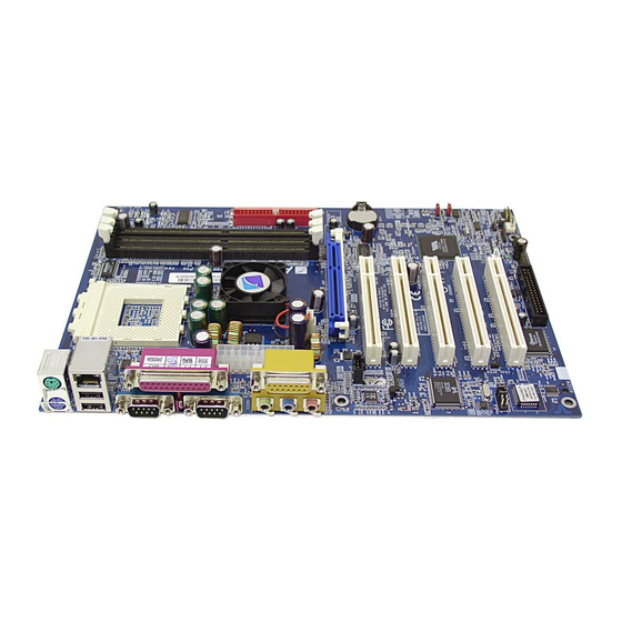
Page 10: Configuration
KX400+ series mainboard Configuration Layout of KX400+ PRO KB/MS CPUFAN PRT/COM ATX_PWR VT8367 AUXFAN SOUND CD-IN PCI 1 PCI 2 BAT1 SPDIF1 VT8235 PCI 3 PCI 4 CASE OPEN PCI 5 PCI 6 CHASFAN USB2 USB3 SW/LED IrDA SPEAKER FRONT AUDIO... - Page 11 KX400+ series mainboard Layout of KX400+ PRO-C KB/MS CPUFAN PRT/COM ATX_PWR VT8367 AUXFAN SOUND CD-IN PCI 1 PCI 2 BAT1 SPDIF1 VT8235 PCI 3 PCI 4 CASE OPEN J1 P PCI 5 PCI 6 CHASFAN US B2 US B3 SW/LED IrDA SPEAKER FRONT AUDIO...
- Page 12 KX400+ series mainboard Layout of KX400+ KB/MS CPUFAN PRT/COM FDC1 ATX_PWR VT8367 AUXFAN SOUND CD-IN PCI 1 PCI 2 BAT1 SPDIF1 VT8233A PCI 3 PCI 4 CASE OPEN PCI 5 PCI 6 CHASFAN USB2 SW/LED SPEAKER IrDA FRONT AUDIO...
-
Page 13: Hardware Installation
KX400+ series mainboard Hardware Installation This section will assist you in quickly installing your system hardware. Wear a wrist ground strap before handling components. Electrostatic discharge may damage your system components. Subject: CPU Processor Installation Memory Installation Back Panel Configuration Connector Configuration Header Configuration Jumper Settings... -
Page 14: Cpu Processor Installation
KX400+ series mainboard CPU Processor Installation ® This mainboard supports AMD Athlon XP / Athlon / Duron processors using a Socket A (Socket 462 Pin package). Before building your system, we suggest you visit the AMD website and review the processor installation procedures. - Page 15 KX400+ series mainboard 3. Lower the lever until it snaps back into position. This will lock down the CPU. 4. Smear thermal grease on the CPU. Lower the CPU fan onto the CPU and use the clasps on the fan to attach it to the socket. Finally, extend the power cable from the fan and insert it into the CPUFAN adapter.
-
Page 16: Fan Headers
KX400+ series mainboard Fan Headers There are three power headers used for cooling fans which play an important role in maintaining the ambient temperature in your system. We strongly recommend you attach the CPU fan to the CPUFAN Header. Ground KB/MS +12V CPUFAN... -
Page 17: Watch Dog Timer
KX400+ series mainboard Frequency / Voltage Control This Mainboard automatically detects and recognizes the CPU ratio. You can otherwise override these values using the BIOS setup. Configuration the CPU Frequency using BIOS Setup BIOS SETUP>>Advanced BIOS>>Features>>Frequency/Voltage Control>>CPU Speed Detected CPU Speed = CPU Ratio * CPU Clock DDR Speed = DDR: CPU Ratio * CPU Clock For more details, please refer to Frequency / Voltage Control in Chapter 2 BIOS Setup. -
Page 18: Memory Installation
KX400+ series mainboard Memory Installation The KX400+ Series contains 3 sockets for 184 pin DDR SDRAM with a total memory capacity of up to 3GB. You can install Unbuffered DDR 333/266/200 (PC2700/2100/1600) SDRAM. DDR DIMM1 DDR DIMM2 DDR DIMM3 The layout is KX400+ PRO... - Page 19 KX400+ series mainboard RAM Module Configuration Setup: Match the notch on the bottom of the RAM module with the corresponding pattern in the DIMM slot. This ensures that the module is inserted properly. Lower the RAM module into the DIMM Slot and press firmly using both thumbs until the module snaps into place.
-
Page 20: Back Panel Configuration
KX400+ series mainboard Back Panel Configuration PS/2 Print Port Game Port Mouse PS/2 COM1 COM2 Speaker Line Keyboard PS/2 Mouse & PS/2 Keyboard Connectors: KB/MS This mainboard provides a standard PS/2 mouse connector and PS/2 Keyboard connector. The pin assignments are described below: PS/2 Assignment Mouse... -
Page 21: Serial And Parallel Interface Ports
KX400+ series mainboard Serial and Parallel Interface Ports This system comes equipped with two serial ports and one parallel port. Print Port COM1 COM2 The Serial Interface: COM1/ COM2 The serial interface port is sometimes referred to as an RS-232 port or an asynchronous communication port. -
Page 22: Connector Configuration
KX400+ series mainboard Connector Configuration Front Panel Indicator: SW/LED SW/LED The layout is KX400+ PRO Assignment Function Assignment Function HD LED (+) Hard Drive Power LED (+) POWER HD LED (-) Power LED (-) Reset Control (-) Reset Power Button(+) Power-on Reset Control(+) Button... - Page 23 KX400+ series mainboard HD LED (Hard Drive LED Connector) This connector can be attached to an LED on the front panel of a computer case. The LED will flicker during disk activity. This disk activity only applies to those IDE drives directly attached to the system board.
- Page 24 KX400+ series mainboard SPEAKER (Speaker Connector) An off-board speaker can be installed on the mainboard as a manufacturing option. An off-board speaker can be connected to this connector. The speaker (onboard or off-board) provides error beep code information during the Power On Self-Test when the computer cannot access the video interface.
- Page 25 KX400+ series mainboard IrDA (Infrared Connector) This IrDA connector can be configured to support wireless infrared and is used to attach to an infrared sensing device. After the IrDA interface is configured, you can use this connector for connectionless data transfer to and from portable devices such as laptops and PDAs.
- Page 26 KX400+ series mainboard Floppy Disk Connector: FDC The mainboard provides a standard floppy disk connector (FDC) that supports 360K, 1.2M, 1.44M and 2.88M floppy disk types. This connector supports the floppy drive ribbon cables provided in the packaging. The layout is KX400+ PRO...
- Page 27 KX400+ series mainboard Hard Disk Connectors: IDE1/IDE2 This mainboard has a 32-bit Enhanced PCI IDE Controller that provides PIO Mode 0~4, Bus Master, and Ultra DMA / 33, Ultra DMA / 66, Ultra DMA / 100, Ultra DMA / 133 functionality. It has two HDD connectors, IDE1 (primary) and IDE2 (secondary).
- Page 28 KX400+ series mainboard Headers & Jumpers Front USB Headers: USB2 / USB3 USB2 USB3 The layout is KX400+ PRO KX400+ The KX400+ comes with one standard USB 1.1 Pin header USB2. KX400+ PRO & KX400+ PRO-C The KX400+ PRO / KX400+ PRO-C comes with two standard USB 2.0 Pin headers USB2 &...
- Page 29 KX400+ series mainboard Wake On LAN Header: WOL This mainboard supports the Wake On LAN function. To use this function, a network card with a chipset that supports this feature is required. A WOL network card will have a cable that you need to attach to this connector. Wake on LAN (WOL) The layout is KX400+ PRO Pin No.
- Page 30 KX400+ series mainboard Clear CMOS Jumper: JP1 Clear CMOS (JP1) The layout is KX400+ PRO Assignment P in 1 Pin 1-2 Close Normal (default) Pin 1 Pin 2-3 Close Clear CMOS The following procedures are for resetting the BIOS password. It is important to follow these instructions closely.
- Page 31 KX400+ series mainboard CPU Frequency Selection: JP2 Use this jumper to adjust the CPU frequency. CPU Frequency (JP2) The layout is KX400+ PRO CPU Frequency 100.0MHz 133.0MHz 166.0MHz...
- Page 32 KX400+ series mainboard OTP (Over Temperature Protection) function: JP4 This mainboard supports a special design for CPU Over Temperature Protection. If this function is “Enabled” and you use Athlon XP CPU, when the CPU temperature rises above the normal range, the system will automatically shut down. Remove and reinstall the CPU heat sink.
- Page 33 KX400+ series mainboard Case Open Warning function: CASE OPEN If this function is “Enabled” and the case had been previously opened, the system will automatically show alert messages on the screen display when you power on your computer. If this function is “Disabled”, the system will disregard any prior tampering with the computer case.
- Page 34 KX400+ series mainboard Voice Genie and BIOS Mirror Function: S1 (KX400+ & KX400+ PRO provide) This switch is used to configure the Voice Genie and BIOS Mirror functions. With S1-1 and S1-2, you can select the appropriate language for audio diagnostics during boot up.
- Page 35 KX400+ series mainboard CPU Ratio Select Switch: SW1 (Optional) This switch is used for CPU overclocking by specifying the ratio of the CPU’s internal clock. You can adjust this value using this switch or you can configure the value through the BIOS setup. Note that the CPU ratio select switch (SW1) takes precedence.
-
Page 36: Audio Function
KX400+ series mainboard Audio Function S/PDIF (SPDIF) CD-ROM Audio IN (CD_IN) Front Panel Audio (FRONT_ AUDIO) D DR DI MM 1 D DR DI MM 2 D DR DI MM 3 ID E1 ID E2 The layout is KX400+ CD-ROM Audio-In Header: CD-IN This header is used to connect to a CD-ROM / DVD audio cable. - Page 37 KX400+ series mainboard S/PDIF (Sony/Philips Digital Interface) Connector: SPDIF S/PDIF (Sony/Philips Digital Interface) is a recent audio transfer file format which provides high quality audio using optical fiber and digital signals. The devices attached to the SPD-OUT and SPD-IN connectors should be S/PDIF compliant for optimal effect.
- Page 38 KX400+ series mainboard Slots The slots in this mainboard are designed for expansion cards used to complement and enhance the functionality of the mainboard. CNR Slot AGP Slot PCI Slots The layout is KX400+ PRO AGP (Accelerated Graphics Port) Slot This mainboard is equipped with an Accelerated Graphics Port (AGP) to support video cards.
-
Page 39: Power Supply Attachments
KX400+ series mainboard Power Supply Attachments ATX 20-pin Power Connector: ATX_PWR This ATX power supply uses a 20-pin connector. Make sure the connector is properly inserted before applying power. ATX_PWR The layout is KX400+ PRO Assignment Assignment +3.3V +3.3V +3.3V -12V PS_ON PW_OK... -
Page 40: Chapter 2. Bios Setup
KX400+ series mainboard Chapter 2. BIOS Setup Introduction This section describes PHOENIX-AWARD™ BIOS Setup program which resides in the ROM BIOS firmware. The Setup program allows users to modify the basic system configuration. The configuration information is then saved to CMOS RAM where the data is sustained by battery after power-down. -
Page 41: Pci Bus Support
KX400+ series mainboard PCI Bus Support This PHOENIX-AWARD™ BIOS also supports Version 2.1 of the Intel PCI (Peripheral Component Interconnect) local bus specification. DRAM Support DDR (Double Data Rate) SDRAM (Synchronous DRAM) are supported. Supported CPUs This PHOENIX-AWARD™ BIOS supports the AMD Athlon , Athlon XP and Duron... -
Page 42: Main Menu
KX400+ series mainboard Main Menu When you enter the PHOENIX-AWARD™ BIOS CMOS Setup Utility, the Main Menu will appear on the screen. The Main Menu allows you to select from several setup functions. Use the arrow keys to select among the items and press <Enter> to accept and enter the sub-menu. -
Page 43: Main Menu Setup Configuration Options
KX400+ series mainboard Main Menu Setup Configuration Options Item Options Description Set the system date. Note that the ‘Day’ automatically Date mm dd yyyy changes when you set the date. Time Hh: mm: ss Set the current time of the system. IDE Primary Options contained in Press <Enter>... -
Page 44: Advanced Bios Features
KX400+ series mainboard Advanced BIOS Features First /Second/Third Boot Device Select your Boot Device Priority. Options: Floppy、LS120、HDD-0、SCSI、CDROM、 HDD-1、HDD-2、HDD-3、ZIP100、USB-FDD、USB-ZIP、USB-CDROM、USB-HDD、 LAN、Disabled Boot Other Device The setting allows the system to try to boot from other devices if the system fails to boot from the 1st/2nd/3rd boot devices. Options: Enabled、Disabled (default) Boot Up Floppy Seek The “Enabled”... -
Page 45: Virus Warning
KX400+ series mainboard Advanced BIOS Features Virus Warning This option allows you to choose the VIRUS warning feature for IDE Hard Disk boot sector protection. If this function is enabled and someone attempt to write data into this area, BIOS will show a warning message on the screen and alarm beep. Options: Disabled (default) Virus protection is disabled. -
Page 46: Gate A20 Option
KX400+ series mainboard Gate A20 Option Fast – let chipset control GateA20 and Normal – a pin in the keyboard controller controls GateA20. Options: Normal (default)、Fast Typematic Rate Setting Keystrokes repeat at a rate determined by the keyboard controller – when enabled, the typematic rate and typematic delay can be selected. -
Page 47: Advanced Chipset Features
KX400+ series mainboard Advanced Chipset Features DRAM Clock/Drive Control Press <Enter> to enter next page for DRAM Clock/Drive Control settings. DRAM CAS Latency This item determines DRAM CAS Latency. When synchronous DRAM is installed, the number of clock cycles of CAS latency depends on the DRAM timing. Do not reset this field from the default value specified by the system designer. -
Page 48: Agp Aperture Size
KX400+ series mainboard AGP Aperture Size Select the size of the Accelerated Graphics Port (AGP) aperture. The aperture is a portion of the PCI memory address range dedicated for graphics memory address space. Host cycles that hit the aperture range are forwarded to the AGP without any translation. -
Page 49: Pci Delay Transaction
KX400+ series mainboard PCI Delay Transaction The chipset has an embedded 32-bit poste write buffer to support delay transactions cycles. Select Enabled to support compliance with PCI specification. Options: Disabled (default)、Enabled Memory Hole When enabled, you can reserve an area of system memory for ISA adapter ROM. When this area is reserved, it cannot be cached. -
Page 50: Irq Resources
KX400+ series mainboard IRQ Resources When resources are controlled manually, assign each system interrupt a type, depending on the type of device using the interrupt. This is only configurable when “Resources Controlled By” is set to “Manual”. IRQ-3 assigned to: PCI device IRQ-4 assigned to: PCI device IRQ-5... -
Page 51: Cpu Ratio
KX400+ series mainboard Frequency/Voltage Control CPU Speed Detected This item displays the CPU speed information detected by the system. CPU Ratio Before you adjust the option, please make sure that your CPU ratio can be adjusted. This item displays the CPU ratio information detected by the system. Options: 5、 5.5、6、6.5、7、7.5、8、8.5、9、9.5、10、10.5、11、11.5、12、12.5 Spread Spectrum The Spread Spectrum function can reduces the EMI (Electromagnetic Interference) -
Page 52: Integrated Peripherals
KX400+ series mainboard Integrated Peripherals Init Display First With systems that have multiple video cards, this option determines whether the primary display uses a PCI Slot or an AGP Slot. Options: AGP (default)、PCI Slot. Voice Genie (with KX400+ & KX400+ PRO) This option allows to enable/disable diagnosis function of Voice Genie. -
Page 53: Via Onchip Ide Device
KX400+ series mainboard VIA OnChip IDE Device If you highlight the literal “Press Enter” next to the “VIA Onchip IDE Device” label and then press the enter key, it will take you a submenu with the following options: IDE Channel 0/1 The mainboard chipset contains a PCI IDE interface with support for two IDE channels. -
Page 54: Ac97 Audio
KX400+ series mainboard AC97 Audio This option allows you to control the onboard AC97 audio. Options: Auto (default)、Disabled Onboard Audio Codec This option allows you to control the onboard audio codec. Options: Enabled (default)、Disabled AC97 Modem (with KX400+ & KX400+ PRO) This option allows you to control the onboard AC97 modem. -
Page 55: Ir Transmission Delay
KX400+ series mainboard RxD, TxD Active This item determines the RxD and TxD frequencies. Options: Hi / Lo (default)、Hi / Hi、Lo / Hi、Lo / Lo. IR Transmission Delay This item allows you to enable/disable IR transmission delay. Options: Enabled (default)、Disabled. UR2 Duplex Mode Select the value required by the IR device connected to the IR port. -
Page 56: Power Management
KX400+ series mainboard Power Management The Power Management Setup Menu allows you to configure your system to utilize energy conservation features as well as power-up/ power-down options. ACPI Suspend Type The item allows you to select the suspend type using the ACPI operating system. Options: S1 (POS) (default) Power on Suspend S3 (STR) Suspend to RAM... -
Page 57: Hdd Power Down
KX400+ series mainboard When not disabled, each of the ranges is from 1 min. to 1 hr. except for HDD Power Down, which ranges from 1 min. to 15 min. and disable. HDD Power Down When enabled, the hard disk drive will power down after a certain configurable period of system inactivity. - Page 58 KX400+ series mainboard PWRON After PWR-Fail This option determines whether you want to restart the system after a power failure, select “On”, to boot the system whether or not the system was on before power failure. Choose Former-Sts, to restore the system to the status before the power failure.
-
Page 59: Irqs Activity Monitoring
KX400+ series mainboard LAN Wake Up To use this function, you need a LAN add-on card which supports power on functions. As well asthe wake-up on LAN jumper. Options: Disabled (default)、 Enabled. PCI PME Wake Up When you select “Enabled”, a PME signal from any PCI card awaken the system. Options: Disabled (default)、Enabled RTC Wake Up When “Enabled”, you can set the date and time at which the RTC (real-time clock) -
Page 60: Hardware Monitoring
KX400+ series mainboard Hardware Monitoring CPU FAN Warning This item is used to monitor CPU FAN status. If you use another method to cool your CPU instead of using the onboard CPUFAN header, you should disable this function. Options: Enabled (default)、Disabled Case Open Warning If this function is set to “Enabled”... -
Page 61: Load Defaults
KX400+ series mainboard Load Defaults Load System Default Settings Load System Default Settings Load System Turbo Settings Load System Turbo Settings Load CMOS From BIOS Load defaults from flash ROM for systems without batteries Save CMOS To BIOS Save defaults to flash ROM for systems without batteries... -
Page 62: Exit Menu
KX400+ series mainboard Exit Menu Save & Exit Setup Save all configuration changes to CMOS (memory) and exit setup. A confirmation message will be displayed before proceeding. Exit Without Saving Abandon all changes made during the current session and exit setup. A confirmation message will be displayed before proceeding. -
Page 63: Chapter 3: Software Setup
KX400+ series mainboard Chapter 3: Software Setup Software List Category Platform VIA Service Pack (4 In 1) USB 2.0 Driver Onboard Audio Driver Windows 9X/ ME/ WinXP USB Wake from S3 Driver 2000/ XP BIOS files PC-cillin 2002 Acrobat Reader... -
Page 64: Software Installation
KX400+ series mainboard Software Installation Place the Driver CD into the CD-ROM drive and the Installation Utility will auto-run. You can also launch the Driver CD Installation Utility manually. Follow the steps below: 1. The first screen (Main Screen) will display two buttons. Click 2. - Page 65 KX400+ series mainboard 3. On the “Onboard Driver Installation” screen, select from the buttons below to install the appropriate drivers. 4. By clicking on the picture in step 2, you will have two programs to choose from and install. Click the appropriate button and follow the instructions.
- Page 66 KX400+ series mainboard 5. Clicking the second button from the screen in step 1, we can browse all the files in the Driver CD. 6. You can click to exit the Drive CD program.
-
Page 67: Super 5.1 Channel Setup
KX400+ series mainboard Super 5.1 Channel Setup This section describes how to configure the Super 5.1 Channel Audio system to produce 2, 4 or 6 channel (speaker) output. 1. From your Windows desktop click the audio icon located in the lower right corner of the desktop. -
Page 68: Speaker Test
KX400+ series mainboard Speaker Test This section describes the steps to test the speakers previously configured as part of your Super 5.1 Channel Audio system. Make sure that all cable is firmly into the connector. from your Windows Desktop, locate the audio icon at the lower right corner of the desktop. -
Page 69: Chapter 4: Troubleshooting
KX400+ series mainboard Chapter 4: Troubleshooting Problem 1: No power to the system. Power light does not illuminate. Fan inside power supply does not turn on. Indicator lights on keyboard are not lit. Causes: 1. Power cable is unplugged. 2. Defective power cable. 3. - Page 70 KX400+ series mainboard Problem 4: System only boots from the CD-ROM. The hard disk can be read and applications can be used but booting from the hard disk is impossible. Causes: Hard Disk boot sector has been corrupted. Solutions: Back up data and applications files. Reformat the hard drive. Re-install applications and data using backup disks.
- Page 71 KX400+ series mainboard Problem 10: Keyboard failure. Causes: Keyboard is disconnected. Solutions: Reconnect keyboard. Replace keyboard if you continue to experience problems. Problem 11: No color on screen. Causes: 1. Faulty Monitor. 2. CMOS incorrectly set up. Solutions: 1. If possible, connect monitor to another system. If no color appears, replace monitor.
Need help?
Do you have a question about the KX400+ Pro-C and is the answer not in the manual?
Questions and answers