Table of Contents
Advertisement
Advertisement
Chapters
Table of Contents

Related Manuals for ADDER ePowerSwitch 8XS


Summary of Contents for ADDER ePowerSwitch 8XS
-
Page 1: User Guide
ePowerSwitch User guide Version 02 2011 www.neol.com... - Page 3 8XS © Copyright by NEOL S.A.S - 4 Rue Nationale, 67800 BISCHHEIM, France Printed in France All rights reserved. No part of this documentation, accompanying software or other components of the described product may be reproduced or transmitted in any form or by any means, electronic or mechanical, including photocopying and recording, for any purpose other than the personal use of the purchaser without the express written permission of NEOL S.A.S.
-
Page 4: Table Of Contents
User Guide CONTENTS SAFETY INSTRUCTIONS: To be read before use! ..................3 Consignes de sécurité : à lire avant utilisation ! .................... 4 1. DESCRIPTION ............................5 1.1. Package list ............................5 1.2 Compatibility tables ..........................5 ... -
Page 5: Safety Instructions: To Be Read Before Use
8XS SAFETY INSTRUCTIONS: To be read before use! NOTE • The ePowerSwitch devices can only be installed by qualified people with the following installation and use instructions. The manufacturer disclaims all responsibility in case of a bad utilization of the ePowerSwitch devices and particularly any use with equipments that may cause personal injury or material damage. -
Page 6: Consignes De Sécurité : À Lire Avant Utilisation
User Guide Consignes de sécurité : à lire avant utilisation ! Français Remarque • Les équipements ePowerSwitch ne peuvent être installés que par un personnel qualifié. Le fabricant décline toute responsabilité en cas de mauvaise utilisation des équipements ePowerSwitch et tout particulièrement en cas d’utilisation avec des équipements pouvant occasionner des blessures corporelles ou des dommages matériels. -
Page 7: Description
8XS is a power distribution and control unit that enables power management of 8 devices through an RS-232 or RS-485 connection. The ePowerSwitch 8XS has two separate power inputs of 10 Amp to increase the security and the load available on the power outlets. -
Page 8: Diagram
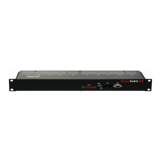
User Guide 3. Diagram 3.1. Front panel LEDs SUB-D9F Connector Terminal connection A = Power supply A B = Power supply B 1 - 8 = Status of outlets 1 - 8 Dip Switches RJ45 Connectors 1 - 4: physical address of device xBus RS485 5 - 6: xBus termination Cascading connection... -
Page 9: Back
8XS 3.2. Back Power outlets (Group A) Power outlets (Group B) Power outlets 1 – 4 Power outlets 5 – 8 230 VAC max 10 Amp 230 VAC max 10 Amp Power input A Power input B 230 VAC – 10 Amp 230 VAC –... -
Page 10: Connection To A Master
1. Connect the appropriate link-up cable to one of the xBus connector of the ePowerSwitch Master and to one of the xBus connector of the ePowerSwitch 8XS. To cascade several Satellites, link the second xBus connector of a Satellite with one of the xBus connector of the next Satellite. - Page 11 2. Allocate an address to each Satellite by positioning the address selection DIP-switches marked "Slct" on the front panel according to the following table. Remarks − Unplug the power cords of the ePowerSwitch 8XS before changing its DIP switches. − Do NOT use the same address for two different Satellites. Satellite...
-
Page 12: Controlling The Satellite Power Outlets Through The Master Web Server
User Guide 5. Controlling the Satellite power outlets through the Master Web Server Start your Web browser and type the IP address of your ePowerSwitch Master or your VizioGuard RMS system. The browser displays the authentication dialog box. Enter a user name and its corresponding password. If you log in as system administrator, you will be able to: - control individually all the power outlets and all the power outlets groups of the Master, - control all the power outlets and all the power outlet groups of the connected satellites,... -
Page 13: Controlling The Satellite Power Outlets Using A Terminal Connection
6.1. Using the RS232 port (SubD-9F connector marked RS232 on the front panel). In this case, use the supplied RS232 serial cable to connect the ePowerSwitch 8XS to an available serial port of your PC. 6.2. Using the RS485 port (RJ45 connector marked xBus on the front panel). -
Page 14: Controlling Of The Power Outlet(S)
10 sec., then switch all power outlets to On after a delay of 20 sec. The ePowerSwitch 8XS accepts lower case and upper case commands. The ePowerSwitch 8XS sends its reply only after having received a valid command terminated by the character [CR]. -
Page 15: Reading Out The Power Outlet Status
R168[CR] Read status of the power outlets #8 of ePowerSwitch #16 The ePowerSwitch 8XS accepts lower case and upper case commands. The ePowerSwitch 8XS sends its reply only after having received a valid command terminated by the character [CR]. Page | 13... -
Page 16: Setting Of The Power Up Delays
T163=10 Set power up delay of the power outlet #3 of ePowerSwitch #16 to 10 sec The ePowerSwitch 8XS accepts lower case and upper case commands. The ePowerSwitch 8XS sends its reply only after having received a valid command terminated by the character [CR]. -
Page 17: Setting The Restart Delays
TR31=17 Set Restart Delay of the Power Outlet #1 of ePowerSwitch #3 to 17 sec The ePowerSwitch 8XS accepts lower case and upper case commands. The ePowerSwitch 8XS sends its reply only after having received a valid command terminated by the character [CR]. -
Page 18: Setting The Power Up Default Status
DP165=OFF Set Power Up Default Status of the Power Outlet #5 of ePowerSwitch #16 to OFF The ePowerSwitch 8XS accepts lower case and upper case commands. The ePowerSwitch 8XS sends its reply only after having received a valid command terminated by the character [CR]. -
Page 19: Reading Out The Switching Counter Values Of The Relays
8XS 6.3.9. Reading out the switching counter values of the relays This command enables to read out the number of power up cycles of the ePowerSwitch 8XS and the number of switching cycles (Off to On) of each power outlet. -
Page 20: Resetting The Switching Counter Values Of The Relays
Reply from the ePowerSwitch 8XS: No reply The ePowerSwitch 8XS accepts lower case and upper case commands. The ePowerSwitch 8XS sends its reply only after having received a valid command terminated by the character [CR]. 6.3.11. Restoring to factory settings This command enables to restore all factory settings. -
Page 21: Technical Data
8XS Technical Data Network connection RJ-45 connector for UTP CAT5 Max. network cable length 100 meters (not included) Serial connection RS232, SUB-D 9 female Connection Bus RS-485, RJ-45 Nominal input voltage 230 V/50Hz Input power outlet IEC-320 Output voltage... -
Page 22: Statement Of Conformity
NEOL S.A.S. 4 Rue Nationale 67800 BISCHHEIM -FRANCE Type of Equipment: Power Control Unit Type Designation: ePowerSwitch 8XS Satellite Reference: EPS 8XS Years of Manufacture: 2010 -2011 We, the undersigned, hereby declare that the equipment specified above conforms to the above directives.
Need help?
Do you have a question about the ePowerSwitch 8XS and is the answer not in the manual?
Questions and answers