Table of Contents
Advertisement
Quick Links
Specifi cation
Number
INSTRUCTIONS
5240
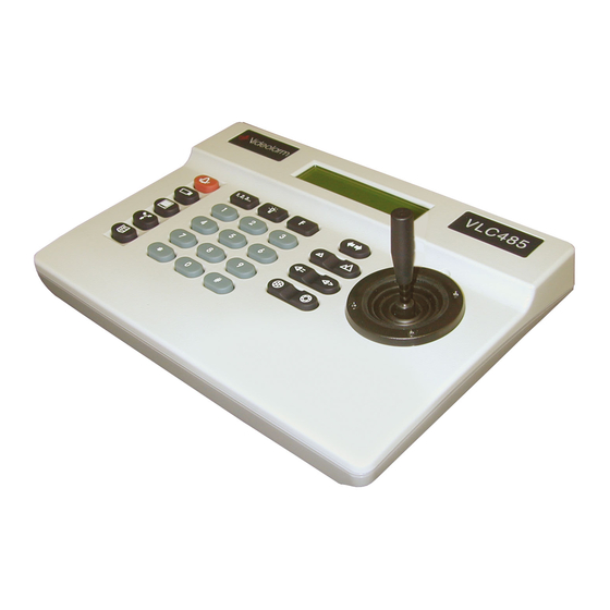
MODEL: Pan/Tilt Controller
VLC485
A NOTE BEFORE BEGINNING
Each camera controlled by the VLC485 must have a unique
address. The default address for most cameras is "1". See the
instructions for your camera for steps to change the address.
1.0 TABLE OF CONTENTS
1.2 Specifi cation
2.3 Pan/Tilt Movement
2525 Park Central Blvd. • Decatur, GA 30035 • (770) 987-7550 • 800-554-1124 • Fax 800-826-0366 • www.videolarm.com
Catalog
Section
2C
Page No.
1
1
1
2
2
2
3
3
3
3
3
3
4
4
4
4
4
4
4
5
5
5
6
6
6
6
6
6
6
7
7
7
for TOSHIBA
PRODUCT INSTRUCTIONS
1.1 GENERAL DESCRIPTION
The VLC485 is a pan/tilt controller that ties together the major
elements of an integrated system and provides a single human
interface for the system. As such, the VLC485 can control pan/tilt
units, interface to multiplexers, and communicate with a personal
computer for computer-controlled operation.
The LCD is used to display current status as well as to provide a
menu system for setting operational parameters.
The VLC485 is designed for desktop operation; all connectors are
located in the rear of the unit so that all cables can be routed from
the back of the unit.
1.2 SPECIFICATIONS
Power Source
Data Connections
Pan/Tilt Control
Camera Control
Multiplexer Control
Confi guration
Display
External Serial
Communications Port
Operating Environment
5v DC 250 ma.
4-pin compression connector:
RS485/422 Pan/Tilt control net-
work.
9-pin d-sub connector: RS232 mul-
tiplexer port.
9-pin d-sub connector: RS232
external serial communications
port.
Maximum number of pan/tilts: 99.
Protocols: Videolarm, Sensormatic,
Pelco, and Kalatel.
Manual control: pan, tilt via joy-
stick.
Speed: Variable.
Presets: go to, set, clear.
Autotour (Videolarm protocol): on,
off, set dwell, set speed.
Manual control: Zoom, focus, iris.
Auto: focus, iris (where supported
by camera).
Protocols: TBD.
Number of channels: up to 32.
Eight external alarm inputs and
one relay contact alarm output.
Menu driven, access controlled
by optional passcode.
LCD, 20 character x 2 lines.
9600 baud, 8 bits, 1 start, 1stop,
no parity
Protocols: Videolarm, Pelco P.
Temperature: 0˚ C - 50˚ C.
Humidity: 90% maximum (non-
condensing).
Altitude: 10,000 ft. maximum.
Advertisement
Table of Contents

Related Manuals for Moog Videolarm VLC485


Summary of Contents for Moog Videolarm VLC485
-
Page 1: Table Of Contents
4.6 Custom Controller LCD Messages Protocols: Videolarm, Pelco P. Operating Environment Temperature: 0˚ C – 50˚ C. Humidity: 90% maximum (non- condensing). Altitude: 10,000 ft. maximum. 2525 Park Central Blvd. • Decatur, GA 30035 • (770) 987-7550 • 800-554-1124 • Fax 800-826-0366 • www.videolarm.com... -
Page 2: Included Accessories
1.3 INCLUDED ACCESSORIES (1) Control Output Connector (1) Alarm Output Connector (1) 5 VDC AC Adapter 1.4 LOCATION AND DESCRIPTION OF CONTROLS Auxiliary Function (for future use) (for future use) Sequence Auto Tour Alarm 1, 2, 3... Camera Zoom Out / Zoom In Monitor Focus Far / Focus Near (for future use) -
Page 3: Connections
1.6 CONNECTIONS 2.0 CONTROL OF THE BASIC FUNCTIONS There are fi ve connectors on the VLC485 Controller. These connec- 2.1 CAMERA SELECTION tors are a 9-pin connector for RS232 connections to a PC, a 9-pin connector for RS232 connections to an external device, a 4-pin... -
Page 4: Autotour
MUX TYPE scroll to the Multiplexer Type. The current type will be dis- The VLC485 sends a command to that camera telling it to go to the played. preset point. When an alarm occurs at that position, the VLC485 will display that camera and alarm. -
Page 5: Autotour Dwell
This parameter is preset in the pan/tilt, but the fi lled a sequence and would like to add cameras to it, do the follow- VLC485 allows you to override that setting via the menu if this feature ing. -
Page 6: Sequence Dwell
4.0 PC PORT The sequence dwell interval defi nes how long the camera will stay The VLC485 uses the PC port to communicate with the serial com- active in the sequence. The factory default dwell time is 3 seconds, munications port of a PC or modem. The PC or other connected but this may be changed to any time between 1 and 99 seconds. -
Page 7: Preset And Dome Parameter Messages
0x0a ignored) FUNCTION BYTE #2 BYTE #3 DESCRIPTION Camera 0x01 - Current camera "C" A message sent to the VLC485 can be cleared at the controller by select 0x63 number pressing the Information button. Monitor "M" 0x01 - Current monitor... - Page 8 The VLC485 can be used in as a stand-alone unit or as part of a system. As part of a system, the unit may be used with another VLC485 or with a PC. Below are diagrams for these types of systems.
- Page 9 Videolarm (1-800-554-1124) for authorization to return and warranty of fi tness for a particular purpose. shipping instructions. In the event of a breach of the above warranty, Videolarm shall, TECHNICAL SUPPORT at its option, repair or replace said product. This is Videolarm's sole obligation under this warranty.
Need help?
Do you have a question about the VLC485 and is the answer not in the manual?
Questions and answers