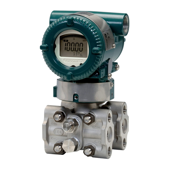
YOKOGAWA DpharpEJX vigilantplant EJX910A User Manual
Fieldbus communication type
Hide thumbs
Also See for DpharpEJX vigilantplant EJX910A:
- User manual (52 pages) ,
- User manual (66 pages) ,
- Installation manual (57 pages)
Table of Contents
Advertisement
Quick Links
Download this manual
See also:
Installation Manual
Advertisement
Table of Contents

Subscribe to Our Youtube Channel
Related Manuals for YOKOGAWA DpharpEJX vigilantplant EJX910A


Summary of Contents for YOKOGAWA DpharpEJX vigilantplant EJX910A
- Page 1 User’s Manual EJX910A Fieldbus Communication Type IM 01C25R03-01E IM 01C25R03-01E 2nd Edition Y okogawa Electric Corporation...
-
Page 2: Table Of Contents
5.6.1 Link Object .................. 5-5 5.6.2 Trend Object ................5-6 5.6.3 View Object ................. 5-6 5.6.4 Function Block Parameters ............5-10 FD No. IM 01C25R03-01E IM 01C25R03-01E 2nd Edition: Sep. 2006(KP) All Rights Reserved, Copyright © 2006, Yokogawa Electric Corporation... - Page 3 CONTENTS EXPLANATION OF BASIC ITEMS............... 6-1 Outline ....................6-1 Setting and Changing Parameters for the Whole Process ....6-1 SENSOR Transducer Block ..............6-1 6.3.1 Functional block ................6-1 6.3.2 Block Mode .................. 6-2 6.3.3 Functions Relating to Differential Pressure ........ 6-2 6.3.4 Functions Relating to Static Pressure .........
- Page 4 CONTENTS PARAMETER LISTS ..................9-1 Resource Block ................... 9-1 SENSOR Transducer Block ..............9-3 FLOW Transducer Block ..............9-7 LCD Transducer Block ..............9-10 Al Function Block ................9-12 Parameter Names Cross Reference ..........9-14 10. GENERAL SPECIFICATIONS ..............10-1 10.1 Standard specifications ..............
- Page 5 CONTENTS APPENDIX 3. INPUT SELECTOR (IS) BLOCK ..........A-21 A3.1 Input Selector Function Block Schematic ......... A-21 A3.2 Input Section ..................A-23 A3.2.1 Mode Handling ................A-23 A3.2.2 MIN_GOOD Handling..............A-23 A3.3 Selection ................... A-24 A3.3.1 OP_SELECT Handling .............. A-24 A3.3.2 SELECTION Handling ...............
- Page 6 CONTENTS A5.14 Initialization and Manual Fallback (IMan) ......... A-48 A5.15 Manual Fallback ................A-48 A5.16 Auto Fallback ..................A-48 A5.17 Mode Shedding upon Computer Failure ........... A-49 A5.17.1SHED_OPT ................A-49 A5.18 Alarms ....................A-49 A5.18.1Block Alarm (BLOCK_ALM) ............A-49 A5.18.2Process Alarms ................. A-49 A5.19 Example of Block Connections ............
-
Page 7: Introduction
Indicates that operating the hardware or software in this manner may damage it or lead to system • Yokogawa makes no warranty of any kind with failure. regard to this manual, including, but not limited to, implied warranty of merchantability and fitness for a particular purpose. -
Page 8: Safe Use Of This Product
(f) Modification contact of toxic process fluids with the skin or eyes. • Yokogawa will not be liable for malfunctions or damage resulting from any modification made to this • When removing the instrument from a hazardous instrument by the customer. -
Page 9: Warranty
- Malfunction or damage due to a failure to handle, operativi di prodotti Ex in lingua locale, mettersi in use, or store the instrument in accordance with the contatto con l’ufficio Yokogawa più vicino o con un design specifications. rappresentante. - Page 10 Si vous nécessitez des instructions relatives aux produits Ex dans votre langue, veuillez bien contacter votre représentant Yokogawa le plus proche. Alle Betriebsanleitungen für ATEX Ex bezogene Produkte stehen in den Sprachen Englisch, Deutsch und Französisch zur Verfügung.
-
Page 11: Handling Cautions
• Explosionproof for Class I, Division 1, to operate. Please contact Yokogawa before making Groups B, C and D. any repair or modification to an instrument. • Dust-ignitionproof for Class II/III, Division 1, Groups E, F and G. - Page 12 2. HANDLING CAUTIONS b. FM Nonincendive Type Note 1. Installation should be in accordance with the National Electrical Code ® (ANSI/NFPA 70) EJX910A Multivariable transmitter with optional code /FN15. Article 500. • Applicable Standard: Class 3600, Class 3611, Note 2. The configuration of Associated Nonincendive Class 3810,ANSI/NEMA250 Field Wiring Apparatus must be FM •...
-
Page 13: Csa Certification
2. HANDLING CAUTIONS FNICO Rules 2.1.2 CSA Certification The FNICO Concept allows the interconnection of a. CSA Explosionproof Type nonincendive field wiring apparatus to associated Caution for CSA explosionproof type. nonincendive field wiring apparatus not specifically Note 1. Model EJX910A Multivariable transmitter examined in such combination. -
Page 14: Cenelec Atex Certification
Equipment • The instrument modification or part replace- ment by other than an authorized representa- 32 V DC Max. 15 mA DC tive of Yokogawa Electric Corporation is Sealing Fitting Signal EJX 910A prohibited and will void KEMA Flameproof F0205E.EPS Certification. - Page 15 (5) Maintenance and Repair 2-9-32 Nakacho, Musashino-shi, Tokyo Japan WARNING The instrument modification or part replacement by other than an authorized Representative of Yokogawa Electric Corporation is prohibited and will void the certification. (6) Name Plate Name plate Tag plate for flameproof type No.
-
Page 16: About Fieldbus
• Carry out scaling, damping and square root extrac- the specification standardized by The Fieldbus Founda- tion. tion, and provides interoperability between Yokogawa (6)SC function block devices and those produced by other manufacturers. • Converts the input signal value based on the Fieldbus comes with software consisting of five AI segment table function. -
Page 17: Logical Structure Of Each Block
3. ABOUT FIELDBUS 3.3 Logical Structure of Each Block EJX910A System/network management VFD Fieldbus PD Tag Communication parameters Node address Function block execution schedule Link Master Function block VFD PID function Transducer block block (option) Block tag AR function block Parameters IS function block... -
Page 18: Getting Started
4. GETTING STARTED GETTING STARTED Fieldbus is fully dependent upon digital communica- Refer to Yokogawa when making arrangements to tion protocol and differs in operation from conven- purchase the recommended equipment. tional 4 to 20 mA transmission and the HART commu- Connect the devices as shown in Figure 4.1. -
Page 19: Host Setting
4. GETTING STARTED 4.2 Host Setting 0x00 Not used To activate Fieldbus, the following settings are 0x0F 0x10 required for the host. Set the available address range to Bridge device 0x13 cover the address set for EJX910A’s. 0x14 LM device V(FUN) Unused V(NUN) -
Page 20: Bus Power On
594543\000E Using the host device display function, check that the (594543 is the manufacturer number of Yokogawa EJX910A is in operation on the bus. Electric Corporation, and 000E is the EJX910A The device information, including PD tag, Node device number, respectively.) -
Page 21: Continuous Record Of Values
4. GETTING STARTED 4.6 Continuous Record of Values If the host has a function that continuously records the indications, use this function to list the indications (values). Depending on the host being used, it may be necessary to set the schedule of Publish (the function that transmits the indication on a periodic basis). -
Page 22: Configuration
5. CONFIGURATION CONFIGURATION • Terminator This chapter describes how to adapt the function and performance of the EJX910A to suit specific applica- Fieldbus requires two terminators. Refer to the tions. Because multiple devices are connected to supplier for details of terminators that are attached Fieldbus, it is important to carefully consider the to the host. -
Page 23: Definition Of Combining Function Blocks
5. CONFIGURATION (LM device) with bus control function (Link Master Table 5.2 Operation Parameter Values of the EJX910A to be Set to LM Devices function) is allocated from a smaller address number (20) side, and other devices (BASIC device) without Symbol Parameters Description and Settings... -
Page 24: Setting Of Tags And Addresses
5. CONFIGURATION 5.4 Setting of Tags and A maximum of 30 ms is taken for execution of AI block. For scheduling of communications for combina- Addresses tion with the next function block, the execution is so This section describes the steps in the procedure to set arranged as to start after a lapse of longer than 30 ms. -
Page 25: Communication Setting
5. CONFIGURATION 5.5 Communication Setting Table 5.4 VCR Static Entry Sub- Parameter Description To set the communication function, it is necessary to index change the database residing in SM-VFD. FasArTypeAndRole Indicates the type and role of communication (VCR). The 5.5.1 VCR Setting following 4 types are used for EJX. -
Page 26: Function Block Execution Control
5. CONFIGURATION 5.6 Block Setting Sub- Parameter Description index Set the parameter for function block VFD. FasDllSubsriberTime Not used for EJX. WindowSize 5.6.1 Link Object FasDllSubscriber Not used for EJX. A link object combines the data voluntarily sent by the SynchronizationDlcep function block with the VCR. -
Page 27: Trend Object
5. CONFIGURATION 5.6.2 Trend Object SMIB (System Transducer Resource AI1 OUT AI2 OUT Management It is possible to set the parameter so that the function block block Information block automatically transmits Trend. EJX910A has Base) NMIB seven Trend objects, six of which are used for Trend in Alert (Network FBOD... - Page 28 5. CONFIGURATION Table 5.11 View Object for Resource Block Relative VIEW VIEW VIEW VIEW Relative VIEW VIEW VIEW VIEW Parameter Mnemonic Parameter Mnemonic Index Index DEVICE_STATUS_2 ST_REV DEVICE_STATUS_3 TAG_DESC DEVICE_STATUS_4 STRATEGY DEVICE_STATUS_5 ALERT_KEY DEVICE_STATUS_6 MODE_BLK DEVICE_STATUS_7 BLOCK_ERR DEVICE_STATUS_8 RS_STATE SOFTDWN_PROTECT TEST_RW SOFTDWN_FORMAT DD_RESOURCE...
- Page 29 5. CONFIGURATION Table 5.12 View Object for SENSOR Transducer Block Relative VIEW VIEW VIEW VIEW VIEW VIEW VIEW Relative VIEW VIEW VIEW VIEW VIEW VIEW VIEW Parameter Mnemonic Parameter Mnemonic Index Index SIMULATE_DPRESS ST_REV TAG_DESC SIMULATE_SPRESS STRATEGY SIMULATE_ETEMP ALERT_KEY EXT_TEMP_SENSOR_SN MODE_BLK CLEAR_CAL CAP_TEMP_VAL...
- Page 30 5. CONFIGURATION Table 5.13 View Object for LCD Transducer Block Table 5.14 View Object for Flow Transducer Block Relative VIEW VIEW VIEW VIEW Relative VIEW VIEW VIEW VIEW VIEW Parameter Mnemonic Parameter Mnemonic Index Index ST_REV ST_REV TAG_DESC TAG_DESC STRATEGY STRATEGY ALERT_KEY ALERT_KEY...
-
Page 31: Function Block Parameters
5. CONFIGURATION Table 5.15 View Object for AI Function Block Table 5.16 Indexes of View for Each Block Relative VIEW VIEW VIEW VIEW VIEW_1 VIEW_2 VIEW_3 VIEW_4 Parameter Mnemonic Index Resourse Block 40100 40101 40102 40103 ST_REV SENSOR Transducer 40202 to 40204 to TAG_DESC 40200... -
Page 32: Explanation Of Basic Items
6. EXPLANATION OF BASIC ITEMS EXPLANATION OF BASIC ITEMS 6.1 Outline (2) Actual (Actual mode): Indicates the current operating condition. This chapter describes the SENSOR transducer block, (3) Permit (Permitted mode): the LCD transducer block, and the AI function block Indicates the operating condition that the block and explains basic parameter settings. -
Page 33: Block Mode
6. EXPLANATION OF BASIC ITEMS Simulation value Pressure Range Adjust- Damping Unit PRIMARY_VALUE /differential ment check processing Check (Channel1) pressure calculation Simulation H-side value static SECONDARY_VALUE Sensor pressure (Channel2) signals Static Range Adjust- Damping Unit pressure ment check processing Check L-side calculation TERTIARY_VALUE... -
Page 34: Functions Relating To Static Pressure
6. EXPLANATION OF BASIC ITEMS Zero-point adjustment by the external screw. CAUTION With pressure being exerted on the point where the adjustment is to be made, zero adjustment needs to be Span adjustment is a function for adjusting the performed. To do this, adjust the calculated value by gradient with respect to the point of zero adjust- turning the external Zero-point adjustment screw, so ment. -
Page 35: Functions Relating To External Temperature
6. EXPLANATION OF BASIC ITEMS Adjustment of static pressure signal: XD_SCALE.Unit in the AI block where The zero/span adjustment function can be used for EXT_TEMP_VAL is selected. Usually, the status static signals, as in the case of differential pressure indicates Good-Non Specific; however, it changes to signals. -
Page 36: Simulation Function
6. EXPLANATION OF BASIC ITEMS (3) The zero point/span adjustment point must be in The flow value becomes the simulation value which is the range -210ºC to 860ºC. calculated by using simulation value of DP, SP and ET. The LCD continuously displays the simulation value and Fixed external temperature mode: alarm (AL.080 SNR.SIM) in alternating sequence. -
Page 37: Block_Err
6. EXPLANATION OF BASIC ITEMS deviates from –50 to 95 C range, set the status of For normal operation, select the Automatic mode. To AMP_TEMP_VAL to Uncertain-Sensor Conversion change important parameters, the O/S mode must be not Accurate. The status under normal conditions is selected. -
Page 38: Flow Unit/Decimal Point Digit
6. EXPLANATION OF BASIC ITEMS • Temp K1 TEMP_K1_FOR_LIQUID ing table summarizes the content of supported • Tb REF_EXT_TEMP_TERATURE XD_ERRORs and error codes. • SPb REF_STATIC_PRESSURE When two or more error codes are being generated (6) Set the operation mode to AUTO. simultaneously, error codes are displayed with prefer- ence given to the largest error code. -
Page 39: Example Displays Of The Integral Indicator
6. EXPLANATION OF BASIC ITEMS Component Contents name Shows the value displayed in the center field for graph numerical values scaled in terms of percentage. Center Presents values of inputs and outputs. While the field for alarm is on, the alarm number alternates with numerical the displayed value here. -
Page 40: Procedure To Set The Built-In Display
6. EXPLANATION OF BASIC ITEMS 6.5.5 Procedure to Set the Built-in Display Select from Parameter Displays (1-4) Specify whether DISPLAY1, DISPLAY2, (DISPLAY_SEL) DISPLAY3, or DISPLAY4 should be displayed. Select items to be displayed in the lower Specify whether tag, parameter, unit, or status text field (INFO_SEL) should be displayed. - Page 41 6. EXPLANATION OF BASIC ITEMS Table 6.1 Parameters to be displayed on LCD Block Name Parameter PARAMETER_SEL Display PRIMARY_VALUE SENSOR PRIMARY_VALUE SECONDARY_VALUE SECONDARY_VALUE SP.HI TRANSDUCER TERTIARY_VALUE TERTIARY_VALUE SP.LO EXT_TEMP_VAL EXT_TMP_VAL EXT.TMP CAP_TEMP_VAL CAP_TEMP_VALUE CAP.TMP APM_TEMP_VAL APM_TEMP_VALUE AMP.TMP FLOW_VALUE FLOW_VALUE FLOW FLOW TRANSDUCER AI1_PV AI1_OUT...
-
Page 42: Units That Can Be Displayed On The Lcd By The Automatic Link Function
6. EXPLANATION OF BASIC ITEMS 6.5.6 Units That Can Be Displayed on the LCD by the Automatic Link Function Index Unit Display on the LCD Index Unit Display on the LCD 1000 1347 m3/s 1001 deg C 1348 m3/m /min 1002 deg F 1349... - Page 43 6. EXPLANATION OF BASIC ITEMS Index Unit Display on the LCD 1559 inH2Oa 1560 inH2Og 1561 Oa(4 C) inH2Oa 1562 Og(4 C) inH2Og 1563 Oa(68 F) inH2Oa 1564 Og(68 F) inH2Og 1565 mmH2Oa 1566 mmH2Og 1567 Oa(4 C) mmH2Oa 1568 Og(4 C) mmH2Og 1569...
-
Page 44: Ai Function Block
6. EXPLANATION OF BASIC ITEMS 6.6 AI Function Block 6.6.4 STATUS_OPT STATUS_OPT is a parameter to select options regard- The AI function block is a unit of the software and ing the status of signals. The AI function block offers executed according to the system schedule. -
Page 45: Basic Parameters Of The Ai Block
6. EXPLANATION OF BASIC ITEMS ALARM_OPTS=HI_HI LO_LO (HI_HI HI LO_LO A case of HI and LO_LO options are selected) HI_HI_LIM HI_HI_LIM OUT_D.value = 0 LO_LO_ OUT_D.value = 1 OUT_D.value = 1 OUT_D.value = 1 OUT_D.value = 1 F0610.EPS Figure 6.6 An Example of OUT_D.value 6.6.6 Basic Parameters of the AI Block Parameter Outline... -
Page 46: In-Process Operation
7. IN-PROCESS OPERATION IN-PROCESS OPERATION 7.2.2 Alarms and Events This chapter describes the procedure performed when changing the operation of the function block of the The following alarms or events can be reported by the EJX910A in process. EJX910A if Link object and VCR static entry are set. Analog Alerts (Generated when a process value 7.1 Mode Transition exceeds threshold) -
Page 47: Simulation Function
7. IN-PROCESS OPERATION 7.3 Simulation Function When Simulate En/Disable in Table 7.2 above is set to 2, the applicable function block uses the simulation There are two simulation functions in EJX910A; one is value set in this parameter instead of the data from the the function commonly offered in FOUNDATION transducer block. -
Page 48: Device Information
8. DEVICE INFORMATION DEVICE INFORMATION 8.1 DEVICE STATUS Device status for the EJX are indicated by using parameter DEVICE_STATUS_1 to DEVICE_STATUS_8 (index 1045 to 1052) in Resource Block. Table 8.1 Contents of DEVICE_STATUS_1 (index 1045) Table 8.2 Contents of DEVICE_STATUS_2 (index 1046) Display Display Hexadecimal... - Page 49 8. DEVICE INFORMATION Table 8.3 Contents of DEVICE_STATUS_3 (index 1047) Table 8.4 Contents of DEVICE_STATUS_4 (index 1048) Display Display Hexadecimal Description Hexadecimal Description through DD through DD 0x80000000 Diff Pressure Input Pressure is outside 0x80000000 AI1 Hi Hi Alarm Hi_Hi Alarm occurs in AI1 outside Range measurement range limit of occurs (AL-30)
- Page 50 8. DEVICE INFORMATION Table 8.5 Contents of DEVICE_STATUS_5 (index 1049) Table 8.7 Contents of DEVICE_STATUS_7 (index 1051) Display Display Hexadecimal Description Hexadecimal Description through DD through DD 0x80000000 Sensor TB Simulation function of Sensor 0x80000000 Diff Pressure Trimming range error for Simulation Active TB is active Span Trim Error...
-
Page 51: Status Of Each Parameter In Failure Mode
8. DEVICE INFORMATION 8.2 Status of each parameter in failure mode Following tables summarize the value of EJX910A parameters when LCD display indicates an Alaram. Table 8.9 Action of each parameters in failure mode related Resource block and Sensor Transducer block Resource SENSOR TB FLOW TB... - Page 52 8. DEVICE INFORMATION Table 8.11 Action of each parameters in failure mode related Function block ALARM Object Cause of Alarm BLOCK_ERR OUT.STATUS Display block AL.21 AI1 block is not scheduled HOLD HOLD NO.SCHD AL.22 AI2 block is not scheduled NO.SCHD AL.23 AI3 block is not scheduled NO.SCHD...
-
Page 53: Parameter Lists
9. PARAMETER LISTS PARAMETER LISTS Note: The Write Mode column contains the modes in which each parameter is write enabled. O/S: Write enabled in O/S mode. MAN: Write enabled in Man mode and O/S mode. AUTO: Write enabled in Auto mode, Man mode, and O/S mode. Resource Block Relative Factory... - Page 54 Version number of interoperability test by Fieldbus Foundation applied to EJX910A. 1042 SOFT_REV – EJX910A software revision number. 1043 SOFT_DESC – Yokogawa internal use. 1044 SIM_ENABLE_MSG Null AUTO Software switch for simulation function. 1045 DEVICE_STATUS_1 – Device status For details, refer to Table 8.1 T0901-2.EPS...
-
Page 55: Sensor Transducer Block
9. PARAMETER LISTS Relative Factory Write Index Parameter Name Explanation Index Default Mode 1046 DEVICE_STATUS_2 – Device status For details, refer to Table 8.2 1047 DEVICE_STATUS_3 Device status For details, refer to Table 8.3 – 1048 DEVICE_STATUS_4 – Device status For details, refer to Table 8.4 1049 DEVICE_STATUS_5 –... - Page 56 9. PARAMETER LISTS Relative Factory Write Index Parameter Name Explanation Index Default Mode 2013 PRIMARY_ 107: differential The type of measurement represented by primary value. VALUE_TYPE pressure 2014 PRIMARY_ – – The measured value and status available to the function VALUE block.
- Page 57 9. PARAMETER LISTS Relative Factory Write Index Parameter Name Explanation Index Default Mode 2037 SP_VALUE_ Range of – High and low range limit values, engineering units, and RANGE capsule decimal point place for static pressure. 2038 CAL_SP_ The highest calibrated value for static pressure POINT_HI 2039 CAL_SP_...
- Page 58 9. PARAMETER LISTS Relative Factory Write Index Parameter Name Explanation Index Default Mode 2059 SIMULATE_ AUTO Sets the differential pressure value and status for simulation. DPRESS 2060 SIMULATE_ AUTO Sets the static pressure value and status for simulation. SPRESS Sets the external temperature value and status for simulation. 2061 SIMULATE_ AUTO...
-
Page 59: Flow Transducer Block
9. PARAMETER LISTS FLOW Transducer Block Relative Factory Write Index Parameter Name Explanation Index Default Mode 2300 Block Header TAG: “FTB” Block Tag Information, such as Block Tag, DD Revision and Execution =O/S Time, relating to this block 2301 ST_REV –... - Page 60 9. PARAMETER LISTS Relative Factory Write Index Parameter Name Explanation Index Default Mode 2325 FIXED_FLOW_ Sets the flow calculation coefficient (Kfactor) used in the VALUE Basic Mode. 2326 REF_STATIC_ 0.101325 Sets the design reference static pressure value used in the PRESSURE Basic Mode.
- Page 61 9. PARAMETER LISTS CAUTION Indexes 2331 to 2353 are parameters for precision volume calculation, and data calculated by the MV setup tool must be written to these parameters. For this reason, these parameters must not be written with data other than that from the MV setup tool. When parameters marked by the “*1”...
-
Page 62: Lcd Transducer Block
9. PARAMETER LISTS LCD Transducer Block Relative Factory Write Index Parameter Name Explanation Index Default Mode 2500 Block Header TAG: “LTB” Block Tag Information on this block such as Block Tag, DD Revision, = O/S Execution Time etc. 2501 ST_REV –... - Page 63 9. PARAMETER LISTS Relative Factory Write Index Parameter Name Explanation Index Default Mode 2520 EXP_MODE1 Selection of the displayed value in exponent such as x1, x10, x100, and x1000. 2521 BLOCK_TAG2 2014 (PRIMARY_ – Block tag which includes a parameter to be displayed on VALUE) display2 2522...
-
Page 64: Al Function Block
9. PARAMETER LISTS Al Function Block Relative Index Index Index Index Index Parameter Factory Write Explanation Index Name Default Mode 4000 4100 4200 4300 4400 Block TAG: “AI1” or Block Tag Information on this block such as Block Tag, DD Header “AI2”... - Page 65 9. PARAMETER LISTS Relative Index Index Index Index Index Parameter Factory Write Explanation Index Name Default Mode 4017 4117 4217 4317 4417 LOW_ Linear: 0% AUTO Limit used in square root processing. A value of zero Square root: percent of scale is used in block processing if the transducer value falls below this limit, in % of scale.
-
Page 66: Parameter Names Cross Reference
9. PARAMETER LISTS Parameter Names Cross Reference Parameter’s name may appear differently according to the tool you use. If you cannot find the designated parameters in the parameters list in the former sections, please use the following cross lists. Sensor Transducer Block Relative Relative Parameter Name... - Page 67 9. PARAMETER LISTS Flow Transducer Block LCD Transducer Block Relative Relative Parameter Name Label Parameter Name Label Index Index BLOCK_HEADER Characteristics BLOCK_HEADER Characteristics ST_REV Static Revision ST_REV Static Revision TAG_DESC Tag Description TAG_DESC Tag Description STRATEGY Strategy STRATEGY Strategy ALERT_KEY Alert Key ALERT_KEY Alert Key...
- Page 68 9. PARAMETER LISTS AI Function Block Relative Parameter Name Label Index BLOCK_HEADER Characteristics ST_REV Static Revision TAG_DESC Tag Description STRATEGY Strategy ALERT_KEY Alert Key MODE_BLK Block Mode BLOCK_ERR Block Error Process Value Output SIMULATE Simulation Wizard XD_SCALE Transducer Scale OUT_SCALE Output Scale GRANT_DENY Grant Deny...
-
Page 69: General Specifications
10. GENERAL SPECIFICATIONS 10. GENERAL SPECIFICATIONS 10.1 Standard specifications Integral Indicator (LCD display) 5-digit Numerical Display, 6-digit Unit Display and Bar For items other than those described below, refer to graph. The indicator is configurable to display one or up to each User’s Manual. - Page 70 10. GENERAL SPECIFICATIONS 10.3 Optional specifications (For Explosion Protected type) Item Description Code FM Explosionproof Approval Applicable Standard: FM3600, FM3615, FM3810, ANSI/NEMA 250 Explosionproof for Class I, Division 1, Groups B, C and D Dust-ignitionproof for Class II/III, Division 1, Groups E, F and G in Hazardous locations, indoors and outdoors (NEMA 4X) Temperature class: T6, Amb.
- Page 71 10. GENERAL SPECIFICATIONS < Factory Setting > Tag Number (Tag plate) As specified in order Software Tag (PD_TAG) ‘FT1001’ unless otherwise both Tag Number and Software Tag specified in order Node Address ‘0xF5’ unless otherwise specified in order Operation Functional Class ‘BASIC’...
-
Page 72: Appendix 1. Signal Characterizer (Sc) Block
APPENDIX 1. SIGNAL CHARACTERIZER (SC) BLOCK APPENDIX 1. SIGNAL CHARACTERIZER (SC) BLOCK The Signal Characterizer (SC) block is used to convert the values of input signals according to a line-segment function. The line-segment function is created using 21 points of the X/Y coordinates specified by the user. This function block can also be used as a transmission line for control signals and supports backward control. - Page 73 APPENDIX 1. SIGNAL CHARACTERIZER (SC) BLOCK Line-segment factor determination section Input section Output section IN_1 OUT_1 Determining processing Determining BLOCK_ERR the gradient the mode and intercept IN_2 OUT_2 Determining the status and computing OUT X or Y CURVE_X SWAP_2 CURVE_Y 1 MODE = AUTO 2 MODE = MAN or O/S FA0102.EPS...
-
Page 74: A1.2 Input Section
APPENDIX 1. SIGNAL CHARACTERIZER (SC) BLOCK A1.2 Input Section The input section determines the mode and judges BLOCK_ERR. A1.2.1 Determining the Mode The following describes operations of the Signal Characterizer block. Supported Mode Rules • System-stopped status (Out of Service) •... -
Page 75: A1.3 Line-Segment Factor Determination Section
APPENDIX 1. SIGNAL CHARACTERIZER (SC) BLOCK A1.3 Line-segment Factor Determination Section When the mode is AUTO and no bit in BLOCK_ERR is set, the "gradient" and "intercept" of a line passing through two points that are considered line-segment approximation values are determined. A1.3.1 Conditions for Configuring Valid Coefficients (CURVE_X, CURVE_Y) No write error is generated with respect to the settings in CURVE_X and CURVE_Y. - Page 76 APPENDIX 1. SIGNAL CHARACTERIZER (SC) BLOCK Example of the case where SWAP_2 is on (monotone increase): The input range of IN_1 is always in CURVE_X. The following shows the input/output graph of the IN_1 values. Output (High limit) (Low limit) X7 =INFINITY Input FA0104.EPS...
-
Page 77: A1.4 List Of Signal Characterizer Block Parameters
APPENDIX 1. SIGNAL CHARACTERIZER (SC) BLOCK A1.4 List of Signal Characterizer Block Parameters View Relative Parameter Write Mode Valid Range Initial Value Description / Remarks Index Information relating to this function block, such as block tag, DD revision, BLOCK_HEADER Block Tag=O/S TAG: "SC"... -
Page 78: A1.5 Application Example
APPENDIX 1. SIGNAL CHARACTERIZER (SC) BLOCK A1.5 Application Example A1.5.1 Input Compensation The following is an application example of pH com- pensation made by performing feedback control. The pH is a value representing the degree of acidity or alkalinity and ranges from 0 to 14. pH 7 indicates neutral, a value smaller than 7 represents acidity, and a value larger than 7 denotes alkalinity. - Page 79 APPENDIX 1. SIGNAL CHARACTERIZER (SC) BLOCK To enable backward control (which inverts the X and Y axes), the line-segment function must be set so that the elements of the curve increase in a monotone manner.(As shown in Figure A1.11) If they do not increase in a monotone manner, the mode changes to O/S, disabling calculation.
-
Page 80: Appendix 2. Integrator (It) Block
APPENDIX 2. INTEGRATOR (IT) BLOCK APPENDIX 2. INTEGRATOR (IT) BLOCK The Integrator (IT) block adds two main inputs and integrates them for output. The block compares the integrated or accumulated value to TOTAL_SP and PRE_TRIP and generates discrete output signals OUT_TRIP or OUT_PTRIP when the limits are reached. -
Page 81: A2.2 Input Process Section
APPENDIX 2. INTEGRATOR (IT) BLOCK A2.2 Input Process Section When executed, the Integrator block first performs input processing in the order of: "Determining input status" "Converting Rate or Accum" "Determining the input flow direction" Switching between Convert Rate and Convert Accum is made using bit 0 (for IN_1) or bit 1 (for IN_2) of INTEG_OPTS. -
Page 82: A2.2.3 Converting Accumulation
APPENDIX 2. INTEGRATOR (IT) BLOCK A2.2.3 Converting Accumulation This following describes an example of accumulation conversion. In accumulation conversion, the difference between the value executed previously and the value executed this time is integrated or accumulated. This conversion applies when the output of a function block used as a counter is input to the input process of the Integrator block. -
Page 83: A2.3 Adder
APPENDIX 2. INTEGRATOR (IT) BLOCK A2.3 Adder When input processing is complete, two arguments that have been rate and accumulate converted will be passed to the adder. The adder adds these two values according to the option. A2.3.1 Status of Value after Addition If one of the statuses of two arguments is "Bad"... -
Page 84: A2.4 Integrator
APPENDIX 2. INTEGRATOR (IT) BLOCK A2.4 Integrator When addition is complete, its result will be passed to the integrator. Integration consists of combinations of a reset method and counting up/down. There are the following seven integration types, which can be set using INTEG_TYPE. 1. -
Page 85: A2.5 Output Process
APPENDIX 2. INTEGRATOR (IT) BLOCK A2.5 Output Process There are the following three output parameters: 1. OUT 2. OUT_TRIP 3. OUT_PTRIP Parameters OUT_TRIP and OUT_PTRIP are used only when INTEG_TYPE is a value from 1 to 4. A2.5.1 Status Determination The same criteria for determining the status of the output of the Integrator block are used in common for the above three parameters. -
Page 86: A2.5.2 Determining The Output Value
APPENDIX 2. INTEGRATOR (IT) BLOCK A2.5.2 Determining the Output Value The value of OUT.Value is determined as follows: For counting up OUT = integration start value (0) + Total For counting down OUT = integration start value (TOTAL_SP) _ Total Total: Total of integrated values. -
Page 87: A2.5.3 Mode Handling
APPENDIX 2. INTEGRATOR (IT) BLOCK For counting up, the OUT value is as follows: OUT < TOTAL_SP - PRE_TRIP OUT_TRIP = 0, COUT_PTRIP = 0 TOTAL_SP - PRE_TRIP <= OUT < TOTAL_SP OUT_TRIP = 0, COUT_PTRIP = 1 TOTAL_SP <= OUT OUT_TRIP = 1, COUT_PTRIP = 1 For counting down, the OUT value is as follows: PRE_TRIP <... -
Page 88: A2.6 Reset
APPENDIX 2. INTEGRATOR (IT) BLOCK A2.6 Reset A2.6.1 Reset Trigger There are the following five types of reset triggers: 1. An integrated value exceeds TOTAL_SP. 2. An integrated value falls below "0." 3. RESET_IN is "H." 4. Every period specified in CLOCK_PER (for more information, see CLOCK_PER in A2.6.2) 5. -
Page 89: A2.6.3 Reset Process
APPENDIX 2. INTEGRATOR (IT) BLOCK A2.6.3 Reset Process The basic reset process sequence is as follows: 1.) Snapshot 2.) Clearing the integrated values 3.) Reset count increment 4.) Judging OUT_TRIP and OUT_PTRIP (see A2.5) 1.) Snapshot Saves the following values in the specified parameters before clearing the integrated values. These values will be retained until the next reset is made. -
Page 90: A2.7 List Of Integrator Block Parameters
APPENDIX 2. INTEGRATOR (IT) BLOCK A2.7 List of Integrator Block Parameters View Parameter Initial Write Index Definition Name Value Mode 1 2 3 4 Block Tag Information relating to this function block, such as block tag, BLOCK_HEADER TAG: "IT" =o/s DD revision, execution time ST_REV 2 2 2 2... - Page 91 APPENDIX 2. INTEGRATOR (IT) BLOCK View Parameter Initial Write Index Definition Name Value Mode 1 2 3 4 CLOCK_PER 86400.0[sec] Specify the period at which a periodic reset is made. PRE_TRIP 100000.0 Set an allowance applied before an integrated value exceeds the setpoint. N_RESET Indicates the number of resets in the range of 0 to 999999.
-
Page 92: Appendix 3. Input Selector (Is) Block
APPENDIX 3. INPUT SELECTOR (IS) BLOCK APPENDIX 3. INPUT SELECTOR (IS) BLOCK The function of the Input Selector (IS) block is to automatically select one signal from multiple input signals using a specified selection method. The IS block is used for selective control in which one measured quantity is selected from multiple measured quanti- ties to be transmitted to the controller as a controlled variable. - Page 93 APPENDIX 3. INPUT SELECTOR (IS) BLOCK Output Parameters (Computation or Selection Results) OUT: Block output SELECTED: Indicates the input number selected using the alternatives. Other Parameters OUT_RANGE : Sets the OUT range. STATUS_OPTS : Option used to specify the handling of various statuses. SELECT_TYPE : Determines the input selection algorithm.
-
Page 94: A3.2 Input Section
APPENDIX 3. INPUT SELECTOR (IS) BLOCK A3.2 Input Section A3.2.1 Mode Handling The Input Selector block’s operations are determined by the mode (parameter name: MODE_BLK). The following describes operations in each mode. Supported Mode Role · System-stopped status (Out of Service) ·... -
Page 95: A3.3 Selection
APPENDIX 3. INPUT SELECTOR (IS) BLOCK A3.3 Selection The following processing is performed after completing input processing. If the number of valid inputs is less than the value of MIN_Good, no input selection is made. A3.3.1 OP_SELECT Handling When a value other than “0” (that is, 1 to 8) is selected for OP_SELECT: The IS block selects the input of the number specified by OP_SELECT regardless of the setting of SELECT_TYPE, propagates the value of that input to OUT, and transmits the input number to SELECTED. -
Page 96: A3.3.2 Selection Handling
APPENDIX 3. INPUT SELECTOR (IS) BLOCK A3.3.2 SELECTION Handling If the value of OP_SELECT is “0,” input selection using SELECT_TYPE is enabled. When SELECT TYPE is “first good” The IS block selects the input with the smallest input number among valid inputs and transmits the value of that input to OUT. - Page 97 APPENDIX 3. INPUT SELECTOR (IS) BLOCK When SELECT TYPE is “Minimum” The IS block selects the input with the minimum value among valid inputs and transmits the value of that input to OUT. The number of the selected input is transmitted to SELECTED. SELECTION IN_1 = 23 IN_2 = 34.5...
- Page 98 APPENDIX 3. INPUT SELECTOR (IS) BLOCK When SELECT TYPE is “Maximum” The IS block selects the input with the maximum value among valid inputs and transmits the value of that input to OUT. The number of the selected input is transmitted to SELECTED. SELECTION IN_1 = 23 IN_2 = 34.5...
- Page 99 APPENDIX 3. INPUT SELECTOR (IS) BLOCK When SELECT TYPE is “Middle” If there is more than one valid input and the number of such input is an odd number, the value of the middle input will be transmitted to OUT. If there is an even number of valid inputs, the average of the middle two inputs is transmitted to OUT.
- Page 100 APPENDIX 3. INPUT SELECTOR (IS) BLOCK If there is an odd number of valid inputs: SELECTION IN_1 = 23 IN_2 = 34.5 OUT = 23.6 IN_3 = 45 IN_4 = 2.34 IN_5 = 23.6 SELECTED = 5 IN_6 = 15.5 IN_7 = 32.5 IN_8 = 27.4 SELECT_TYPE = Middle...
- Page 101 APPENDIX 3. INPUT SELECTOR (IS) BLOCK When SELECT TYPE is “Average” The block calculates the average of the valid inputs and transmits it to OUT. The number of inputs used to calculate its value is indicated in SELECTED. SELECTION IN_1 = 23 IN_2 = 34.5 OUT = 25.48 IN_3 = 45...
-
Page 102: A3.4 Output Processing
APPENDIX 3. INPUT SELECTOR (IS) BLOCK A3.4 Output Processing A3.4.1 Handling of SELECTED For the value output to SELECTED when OP_SELECT has been selected (that is, not “0”), the number specified by OP_SELECT will be stored as is. However, “0” is stored in the SELECTED in the following cases: 1. -
Page 103: A3.4.2 Out Processing
APPENDIX 3. INPUT SELECTOR (IS) BLOCK A3.4.2 OUT Processing OUT is an output parameter used to send the value selected in the IS block to another function block. The following describes OUT processing. Table A3.3 Block Mode and Value Value MODE ·... -
Page 104: A3.4.3 Status_Opts
APPENDIX 3. INPUT SELECTOR (IS) BLOCK A3.4.3 STATUS_OPTS Description Use Uncertain as Good Causes all inputs (OP_SELECT, IN_n, and DISABLE_n) the status of which is “uncertain,” to be handled as “good” (NC) status inputs and the Uncertain if Man mode When the mode is Man, the status of OUT is interpreted as “uncertain.” (This does not apply to SELECTED.) TA0306.EPS A3.5 List of Input Selector Block Parameters... -
Page 105: A3.6 Application Example
APPENDIX 3. INPUT SELECTOR (IS) BLOCK A3.6 Application Example The following describes the temperature control system of a fixed bed-type reactor. In this case, there are instances where the point showing the maximum temperature changes due to catalytic deterioration, raw material flow, etc. Therefore, a large number of measurement points are provided, and the maximum value obtained among these measurement points is input to the controller to control reactor temperature. -
Page 106: Appendix 4. Arithmetic (Ar) Block
APPENDIX 4. ARITHMETIC (AR) BLOCK APPENDIX 4. ARITHMETIC (AR) BLOCK The Arithmetic (AR) block switches two main inputs of different measurement ranges seamlessly and combines the result with three auxiliary inputs through the selected compensation function (10 types) to calculate the output. A4.1 Arithmetic Function Block Schematic The diagram below shows the Arithmetic block schematic. -
Page 107: A4.2 Input Section
APPENDIX 4. ARITHMETIC (AR) BLOCK A4.2 Input Section PV is a parameter with status information, and PV status is determined by the value of “g.” There are five inputs: IN and IN_LO main inputs and If “g” < 0.5 The status of IN_LO is used. IN_1, IN_2, and IN_3 auxiliary inputs. -
Page 108: A4.2.3 Input_Opts
APPENDIX 4. ARITHMETIC (AR) BLOCK A4.2.3 INPUT_OPTS · If the status of IN is anything other than “good” and that of “IN_LO” is “good” INPUT_OPTS has an option that handles an input with IN_LO < RANGE_HI PV = IN_LO “uncertain” or “bad” status as a “good” status input. IN_LO RANGE_HI See A4.2.1. -
Page 109: A4.3 Computation Section
APPENDIX 4. ARITHMETIC (AR) BLOCK A4.3 Computation Section A4.3.2 Compensated Values In computing equations 1) to 5) in A4.3.1, the value A4.3.1 Computing Equations “f” is restricted by the COMP_HI_LIM or COMP_LO_LIM parameter. In this case, the value “f” This subsection shows computing equations used in the is treated as follows: computation section: If “f”... -
Page 110: A4.4.1 Mode Handling
APPENDIX 4. ARITHMETIC (AR) BLOCK A4.4.1 Mode Handling A4.4.2 Status Handling The setting of INPUT_OPTS is applied to the input Mode Output status. When INPUT_OPTS is applied, there are cases Auto OUT = PRE_OUT where the PV status becomes “good” even if the status of main inputs is “uncertain”... -
Page 111: A4.5 List Of The Arithmetic Block Parameters
APPENDIX 4. ARITHMETIC (AR) BLOCK A4.5 List of the Arithmetic Block Parameters View Relative Parameter Write Mode Valid Range Initial Value Description / Remarks Index BLOCK_HEADER TAG=“AR” Information relating to this function block, such as block tag, DD revision, and execution time Indicates the revision level of the set parameters associated with the Arithmetic ST_REV block. - Page 112 APPENDIX 4. ARITHMETIC (AR) BLOCK View Relative Parameter Write Mode Valid Range Initial Value Description / Remarks Index Computation algorithm identification no. Value Selection Name Description Flow compensation, linear Flow compensation (linear) Flow compensation, square root Flow compensation (square root) Flow compensation, approximate Flow compensation (approximate expression) BTU flow (*)
-
Page 113: Appendix 5. Pid Block
APPENDIX 5. PID BLOCK APPENDIX 5. PID BLOCK A PID block performs the PID control computation based on the deviation of the measured value (PV) from the setpoint (SV), and is generally used for constant-setpoint and cascaded-setpoint control. A5.1 Function Diagram The figure below depicts the function diagram of a PID block. - Page 114 APPENDIX 5. PID BLOCK A5.3 Parameters of PID Block NOTE: In the table below, the Write column shows the modes in which the respective parameters can be written. A blank in the Write column indicates that the corresponding parameter can be written in all modes of the PID block. A dash (-) indicates that the corresponding parameter cannot be written in any mode.
- Page 115 APPENDIX 5. PID BLOCK Parameter Default Index Write Valid Range Description Name (factory setting) SHED_OPT Action to be performed in the event of mode shedding. SHED_OPT defines the changes to be made to MODE.BLK.target and MODE.BLK.actual when the value of RCAS_IN.status or ROUT_IN.status becomes Bad if .MODE_BLK.actual = RCas or ROut.
-
Page 116: A5.4.1 Pv-Proportional And -Derivative Type Pid (I-Pd) Control Algorithm
APPENDIX 5. PID BLOCK A5.4 PID Computation Details A5.5 Control Output The final control output value, OUT, is computed A5.4.1 PV-proportional and -derivative based on the change in control output MVn, which is Type PID (I-PD) Control Algorithm calculated at each control period in accordance with the For PID control, the PID block employs the PV- aforementioned algorithm. - Page 117 APPENDIX 5. PID BLOCK A5.8 Feed-forward Block Description Mode Feed-forward is an action to add a compensation output IMan Initialization and manual mode, in which the control signal FF_VAL to the output of the PID control action is suspended. The PID block enters this mode when the specified condition is met computation, and is typically used for feed-forward (see Section A5.14).
- Page 118 APPENDIX 5. PID BLOCK A5.10 Bumpless Transfer A5.12 External-output Tracking Prevents a sudden change in the control output OUT at External tracking is an action of outputting the value of changes in block mode (MODE_BLK) and at switch- the remote output TRK_VAL set from outside the PID ing of the connection from the control output OUT to block, as illustrated in the figure below.
- Page 119 APPENDIX 5. PID BLOCK A5.15 Manual Fallback Options in Description CONTROL_OPTS Manual fallback denotes an action in which a PID Bypass Enable This parameter allows BYPASS to be set. block changes mode to Man and suspends the control SP-PV Track Equalizes SP to PV when action.
-
Page 120: A5.17.1Shed_Opt
APPENDIX 5. PID BLOCK A5.17 Mode Shedding upon Com- NOTE: If a control block is connected as a cascade primary block of the PID block in question, a mode transition of the PID block puter Failure to Cas occurs in the following sequence due to initialization of the cascade connection: RCas or ROut Auto Cas. -
Page 121: A5.19 Example Of Block Connections
APPENDIX 5. PID BLOCK A5.19 Example of Block Connec- A5.20 View Object for PID Func- tions tion Block Relative VIEW VIEW VIEW VIEW Parameter Mnemonic Index ST_REV TAG_DESC STRATEGY ALERT_KEY MODE_BLK BLOCK_ERR BKCAL_IN CAS_IN PV_SCALE OUT_SCALE BKCAL_OUT GRANT_DENY FA0106.EPS CONTROL_OPTS When configuring a simple PID control loop by combining an EJX transmitter with a fieldbus valve STATUS_OPTS... - Page 122 APPENDIX 5. PID BLOCK Relative VIEW VIEW VIEW VIEW Parameter Mnemonic Index SHED_OPT RCAS_OUT ROUT_OUT TRK_SCALE TRK_IN_D TRK_VAL FF_VAL FF_SCALE FF_GAIN UPDATE_EVT BLOCK_ALM ALARM_SUM ACK_OPTION ALARM_HYS HI_HI_PRI HI_HI_LIM HI_PRI HI_LIM LO_PRI LO_LIM LO_LO_PRI LO_LO_LIM DV_HI_PRI DV_HI_LIM DV_LO_PRI DV_LO_LIM HI_HI_ALM HI_ALM LO_ALM LO_LO_ALM DV_HI_ALM...
-
Page 123: Appendix 6. Link Master Functions
APPENDIX 6. LINK MASTER FUNCTIONS APPENDIX 6. LINK MASTER FUNCTIONS A6.1 Link Active Scheduler A link active scheduler (LAS) is a deterministic, centralized bus scheduler that can control communications on an H1 fieldbus segment. There is only one LAS on an H1 fieldbus segment. An EJX910A supports the following LAS functions. -
Page 124: A6.3 Transfer Of Las
APPENDIX 6. LINK MASTER FUNCTIONS A6.3 Transfer of LAS There are two procedures for an LM to become the LAS: • If the LM whose value of [V(ST) V(TN)] is the smallest on a segment, with the exception of the current LAS, judges that there is no LAS on the segment, in such a case as when the segment has started up or when the current LAS has failed, the LM declares itself as the LAS, then becomes the LAS. -
Page 125: A6.4 Lm Functions
APPENDIX 6. LINK MASTER FUNCTIONS A6.4 LM Functions Function Description LM initialization When a fieldbus segment starts, the LM with the smallest [V(ST) V(TN)] value within the segment becomes the LAS. At all times, each LM is checking whether or not a carrier is on the segment. -
Page 126: A6.5 Lm Parameters
APPENDIX 6. LINK MASTER FUNCTIONS A6.5 LM Parameters A6.5.1 LM Parameter List The tables below show LM parameters. Meanings of Access column entries: RW = read/write possible; R = read only Default Factory Index Sub-parameter Name Parameter Name Access Remarks (SM) (Sub Index) Setting... - Page 127 APPENDIX 6. LINK MASTER FUNCTIONS Index Sub-parameter Name Default Factory Access Parameter Name Remarks (SM) (Sub Index) Setting PLME_BASIC_ CHARACTERISTICS 1 ChannelStatisticsSupported 0x00 2 MediumAndDataRatesSupported 0x4900000000000000 3 IecVersion 1 (0x1) 4 NumOfChannels 1 (0x1) 5 PowerMode 0 (0x0) CHANNEL_STATES 1 channel-1 0 (0x0) 2 channel-2 128 (0x80)
-
Page 128: A6.5.2 Descriptions For Lm Parameters
APPENDIX 6. LINK MASTER FUNCTIONS (5) MaxTokenHoldTimeArray A6.5.2 Descriptions for LM Parameters An 8 64 byte array variable, in which each set of 2 The following describes LM parameters of an bytes represents the delegation time (set as an octet EJX910A transmitter. - Page 129 SchedulesPer of sub-schedules an LAS IceVersion 0x0403 IEC 4.3 is Schedule schedule can contain. (This is supported. fixed to 1 in the Yokogawa NumOf communication stacks.) Channels ActiveSchedule Indicates the version number of Power 0: Bus-powered; Version the schedule currently executed.
-
Page 130: A6.6 Faqs
APPENDIX 6. LINK MASTER FUNCTIONS • 0xFF (true) to Sub- Size Element Description index [bytes] PrimaryLinkMasterFlagVariable (index 364) Version Indicates the version number of in the EJX910A. the LAS schedule downloaded to the corresponding domain. On a segment where an EJX910A works as Macrocycle Indicates the macro cycle of the the LAS, another device cannot be connected. -
Page 131: Appendix 7. Software Download
Upon http://www.yokogawa.com/fld/fld-top-en.htm completion of a download, however, the devices will be reset internally to make the new, down- loaded software take effect, and this will halt... -
Page 132: A7.4 Software Download Sequence
APPENDIX 7. SOFTWARE DOWNLOAD CAUTION NOTE The current dissipation of the target field device The download tool can not execute downloading increases transitorily immediately after a down- during other system connects to the system/ load due to erasing of the FlashROM’s contents. network management VFD of the device. -
Page 133: A7.6 Steps After Activating A Field Device
APPENDIX 7. SOFTWARE DOWNLOAD The device type is “000E” for an EJX910A transmitter. The software name is “ORIGINAL” or “UPDATE.” The former indicates an original file and the latter an update file. Whenever performing a download to update the device revision, obtain the original file. In general, an addition to the parameters or blocks requires a device revision update. -
Page 134: A7.7 Troubleshooting
APPENDIX 7. SOFTWARE DOWNLOAD A7.7 Troubleshooting For information on the download tool’s error messages, see also the software’s User’s Manual. Table A7.2 Problems after Software Update Symptom Cause Remedy An error occurs before starting a The selected download file is not for the Check SOFTDWN_ERROR in the resource download, disabling the selected field device. - Page 135 APPENDIX 7. SOFTWARE DOWNLOAD Table A7.4 Download Error Codes Error Code Detail No error 32768 Unsupported header version 32769 Abnormal header size 32770 Abnormal manufacturer ID 32771 Abnormal device family 32772 Abnormal device revision 32773 Abnormal vendor specification version 32774 Abnormal number of modules 32775 Abnormal number of bytes in module 1...
-
Page 136: A7.9 System/Network Management Vfd Parameters Relating To Software Download
APPENDIX 7. SOFTWARE DOWNLOAD A7.9 System/Network Management VFD Parameters Relating to Soft- ware Download Table A7.5 System/Network Management VFD Parameters Write Mode: R/W = read/write; R = read only Index Default Write Parameter Name Sub-parameter Name Remarks (SM) Index (Factory Set) Mode DWNLD_PROPERTY Download Class... -
Page 137: A7.10 Comments On System/Network Management Vfd Parameters
APPENDIX 7. SOFTWARE DOWNLOAD A7.10 Comments on System/Network Management VFD Parameters Relating to Software Download IMPORTANT Do not turn off the power to a field device immediately after changing parameter settings. Data writing actions to the EEPROM are dual redandant to ensure reliability. If the power is turned off within 60 seconds after setup, the parameters may revert to the previous settings. - Page 138 APPENDIX 7. SOFTWARE DOWNLOAD (2) DOMAIN_DESCRIPTOR Size Element Description (Bytes) Index Command Reads/writes software download commands. 1: PREPARE_FOR_DWNLD (instruction of download preparation) 2: ACTIVATE (activation instruction) 3: CANCEL_DWNLD (instruction of download cancellation) State Indicates the current download status. 1: DWNLD_NOT_READY (download not ready) 2: DWNLD_PREPARING (download under preparation) 3: DWNLD_READY (ready for download) 4: DWNLD_OK (download complete)
-
Page 139: Revision Record
REVISION RECORD Title: Model EJX910A Fieldbus Communication Type Manual No.: IM 01C25R03-01E Edition Date Page Revised Item Jun. 2006 – New publication Sep. 2006 – Correct errors. 9-14 Add ‘9.6 Parameter Names Cross Reference.’ REVISION RECORD.EPS IM 01C25R03-01E...
Need help?
Do you have a question about the DpharpEJX vigilantplant EJX910A and is the answer not in the manual?
Questions and answers