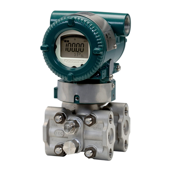
YOKOGAWA DpharpEJX vigilantplant EJX910A User Manual
Multivariable transmitter hart communication type
Hide thumbs
Also See for DpharpEJX vigilantplant EJX910A:
- User manual (66 pages) ,
- User manual (139 pages) ,
- Installation manual (57 pages)

Subscribe to Our Youtube Channel
Related Manuals for YOKOGAWA DpharpEJX vigilantplant EJX910A


Summary of Contents for YOKOGAWA DpharpEJX vigilantplant EJX910A
- Page 1 User’s Manual EJX910A Multivariable Transmitter HART Communication Type IM 01C25R02-01E IM 01C25R02-01E 1st Edition Y okogawa Electric Corporation...
-
Page 2: Table Of Contents
Flow Setup ..................3-15 DP Setup ..................3-15 SP Setup ..................3-15 ET Setup ..................3-16 Total Flow ..................3-16 FD No. IM 01C25R02-01E IM 01C25R02-01E 1st Edition: May 2005 (KP) All Rights Reserved, Copyright © 2005, Yokogawa Electric Corporation... - Page 3 CONTENTS 3.5.2 External Temperature Fixation Mode ......... 3-16 3.5.3 User unit configuration for total flow .......... 3-17 3.5.4 Integral Indicator Scale Setup ............ 3-17 Display Selection ................3-18 Cyclic Display ................3-18 Display Resolution ................ 3-18 User Setting of Engineering Unit and Scale ........ 3-18 3.5.5 Burst Mode .................
-
Page 4: Introduction
Yokogawa’s written understanding the operation and features. permission. • Yokogawa makes no warranty of any kind with regard to this manual, including, but not limited to, implied warranty of merchantability and fitness for a particular purpose. -
Page 5: Safe Use Of This Product
1. INTRODUCTION (e) Modification 1.1 Safe Use of This Product • Yokogawa will not be liable for malfunctions or For the safety of the operator and to protect the damage resulting from any modification made to this instrument and the system, please be sure to follow this instrument by the customer. -
Page 6: Atex Documentation
Se si desidera ricevere i manuali operativi di prodotti Ex in lingua locale, mettersi in Alle Betriebsanleitungen für ATEX Ex bezogene contatto con l’ufficio Yokogawa più vicino o con un Produkte stehen in den Sprachen Englisch, Deutsch rappresentante. -
Page 7: Matching Of Communicator Dd And Instrument Dd
1) Turn on only the communicator. 2) Call Utility from the main menu and press 3) Call Simulation and press 4) Select YOKOGAWA from the list of manufacturers by pressing and press 5) Select the model name of the instrument(i.e. -
Page 8: Conditions Of Communication Line
2. CONDITIONS OF COMMUNICATION LINE CONDITIONS OF COMMUNICATION LINE The HART communication signal is superimposed 2.2 Communication Line onto the 4 to 20 mA DC analog signal. Since the Requirements modulated wave is a communication signal, superim- posing it on the normal signal will, from basic prin- Specifications for communication line: ciples, cause no error in the DC component of the Supply voltage (general use type): 16.6 to 42 V DC... -
Page 9: Operation
3. OPERATION OPERATION 3.1 Basic Operation of the 275 HART Communicator 3.1.1 Keys and Functions Communication cable LCD (liquid crystal display) (21 characters 8 lines) Function keys Functions of the keys are indicated on the display. Pressing (HOME) when the display is as shown changes the display to the Online EJX: menu. -
Page 10: Display
Tag (8 characters) <a> current menu device, or mark because of a current menu data to send comunication error EJX :YOKOGAWA PGUP PGDN Online answer to move up one move down one answer to <b> 1 Device setup... -
Page 11: Entering, Setting, And Sending Data
Display appears when the 5 PV URV ENTER HART Communicator is turned on. Select Device setup. Example: To change from Tag YOKOGAWA to FI1-1A. Call up the Tag setting display. EJX-MV:YOKOGAWA Device setup 1 Process Varlables 2 Diag/Service 1. Device setup... -
Page 12: Parameter Usage And Selection
3. OPERATION 3.2 Parameter Usage and IMPORTANT Selection After setting and sending data with the HART communicator, wait 30 seconds before turning Before setting a parameter, please see the following off the transmitter. If it is turned off too soon, the table for a summary of how and when each parameter settings will not be stored in the transmitter. -
Page 13: Menu Tree
3. OPERATION 3.3 Menu Tree Online (Device setup) 1 Device setup 1 Process variables 2 PV 2 Diag/Servic 3 PV AO 3 Basic setup D, E 4 LRV 4 Detailed setup 5 URV 5 Review Hot key 1 Keypad input 1 PV is 2 Change PV Assgn 3 PV Unit... - Page 14 3. OPERATION 2 Diag/Service 1 Status 1 Status group 1 2 Status group 2 3 Status group 3 4 Status group 4 5 Status group 5 6 Status group 6 7 Status group 7 1 Loop test 8 Status group 8 2 Self test 3 Master test 2 Test...
- Page 15 3. OPERATION 1 Tag 3 Basic setup 1 Pres Unit 2 Units 2 SP Unit 3 ET Unit 4 Flow Unit 5 Total Flow Unit 3 Keypad input 1 PV is 2 Change PV Assgn 3 PV Unit 4 PV LRV 5 PV URV 6 PV Damp 4 Device infomation...
- Page 16 3. OPERATION 4 Detailed setup 1 Sensors 1 Pres 1 Pres LRV 2 SP 2 Pres URV 3 Cap temp 3 Pres Unit 5. Review 4 Amp temp 4 Pres LSL 1 Flow LRV 5 ET 5 Pres USL 2 Flow URV 6 Pres Min span 3 Flow Unit 7 Pres Damp...
- Page 17 3. OPERATION 4 Detailed setup 1 Sensors 1 Disp1 2 Disp2 2 Signal condition 3 Output condition 3 Disp3 5. Review 1 Disp select 4 Disp4 4 Display condition 2 Disp % Reso 1 Flow disp point 2 Pres disp point 3 Disp condition 3 SP disp point 4 ET disp point...
-
Page 18: Basic Setup
8. Output vars number of characters to be set for other items is as 2. SV shown below. 2. Change SV assgn Item Number of characters Descriptor EJX-MV:YOKOGAWA Current SV is Pres Message Select new SV 1 Flow Date 2/2/2 2 Pres... -
Page 19: Keypad Input
PV at that time is changed. For 3. Keypad input example, when PV LRV is changed in the state whose PV is Pres, Pres LRV is changed too. EJX-MV:YOKOGAWA Keypad input 1 PV LRV 0.0 mmH2O 2 PV URV 2500.0 mmH2O... -
Page 20: Pv Unit
SEND ‘0 . 5’ EJX-MV:YOKOGAWA F0309.EPS PV Damp 2.00 sec Note that the Yokogawa default setting for the standard (ENTER) temperature is 4 C (39.2 F). For the units of mmH HELP ENTER Enter 0.5 and press ENTER (F4). O, and ftH O, the pressure varies according to the standard temperature definition. -
Page 21: Sp Unit
Example: Change the unit for the temperature display from degC to degF. 3. Basic setup 2. Units 1. Device setup 3. SP Unit 3. Basic setup 2. Units EJX-MV:YOKOGAWA SP Unit 3. ET Unit mmH2O kg/cm2 torr EJX-MV:YOKOGAWA HELP SEND... -
Page 22: Flow Unit
Example: Change the unit for the flow display from kg/h to kg/d. 1. Device setup 1. Device setup 3. Basic setup 3. Basic setup 2. Units 2. Units 5. Total Flow Unit 4. Flow Unit EJX-MV:YOKOGAWA Flow Unit EJX-MV:YOKOGAWA Flow Unit Kg/h kg/min Kg/h Kg/d HELP SEND... -
Page 23: Output Signal Low Cut Mode Setup
OFF at the factory. 3. Basic setup 5. Others Example: To set the low cut range to 20% and the cut mode 3. H/L Swap to ZERO in the Pres output, proceed as follows. EJX-MV:YOKOGAWA H/L Swap Normal Normal Reverse HELP... -
Page 24: Et Setup
External. Temperature Fixation Mode. 8. Fixed ET e. Total Flow The Total Flow parameters allow the setting of the EJX-MV:YOKOGAWA Fixed ET unit for the total flow, the scaled pulse rate, and total 1 ET Fixed 2 Fixed Et Val flow measuring mode. -
Page 25: User Unit Configuration For Total Flow
2. Signal condition (Pres) –99999 to 99999. 5. Total Flow PRES 45.6 kPa 6. Config User Unit EJX-MV:YOKOGAWA Input static pressure Indicates values of input static Config User Unit 1 Cvt Val (SP) pressure with the indication limits 2 Set Base Unit 3 Modify Unit –99999 to 99999. -
Page 26: Display Selection
Select the unit from the Set Engr Unit list. 4. Display condition 1. Disp select ftH2O Nl/min 1. Disp1 gf/cm2 Nm3/h mbar kgf/cm2 Nm3/min kg/cm2G ACFH EJX-MV:YOKOGAWA Disp1 PV % kg/cm2A ACFM PV % Flow psia SCFH Pres mmH2O kg/h SCFM... -
Page 27: Burst Mode
Call up the Burst option, and set Xmtr Variables the data to be sent. HELP ENTER • PV: Primary variable (Pressure ‘– 5 0’ EJX-MV:YOKOGAWA value) Engr LRV • % range/current: Output in % and (ENTER) • Process vars/crnt: Output in mA and process variables (pressure ENTER Call up the Engr LRV Display.Set... -
Page 28: Multidrop Mode
3. OPERATION 3.5.6 Multidrop Mode Example: Communication when set in multidrop mode. ”Multidropping” transmitters refers to the connection of several transmitters to a single communications (1) The HART communicator HART Communicator transmission line. Up to 15 transmitters can be con- Online searches for a transmitter that is 1 EJX910A-1... -
Page 29: Cpu Failure Burnout Direction And Hardware Write Protect
3. OPERATION 3.5.8 CPU Failure Burnout Direction and 3.5.9 Simulation Mode Hardware Write Protect The flow value can be calculated by using pseudo There are two slide switches on the CPU assembly values instead of using actual measurements of board. One sets the burnout direction at CPU failure, differential pressure, static pressure, and external and the other sets a write protection function which temperature. - Page 30 3. OPERATION Example: Set the simulation mode to (DP, SP, ET) = (ON, ON, ON). 1. Device setup 4. Detailed setup 7. Simulation EJX-MV:Yokogawa Simulation 1 Simulation Mode 2 Sim Pres Unit 3 Sim Pres 0.000 4 Sim SP Unit To set the simulation mode, select 5 Sim SP 101.32...
- Page 31 3. OPERATION Example: Setting of simulation condition: ‘5’ DP = 5kPa, SP = 5MPa, ET = 98degC. EJX-MV:YOKOGAWA Sim Pres 101.32kPa 1. Device setup (ENTER) 4. Detailed setup HELP ENTER Set ’5’and press ENTER (F4). 7. Simulation EJX-MV:YOKOGAWA Simulation EJX-MV:YOKOGAWA...
-
Page 32: Basic Flow Calculation
This is called ”Basic mode.” Example: Enable Basic mode. 1. Device setup 4. Detailed setup 8. Basic Flow Calc EJX-MV:Yokogawa Basic Flow Calc 1 Flow Calc Mode 2 Fluid Type 3 Flow Calc Fixed 4 Ref Sp... - Page 33 3. OPERATION Table 3.4 Flow Factor Flow unit category Table 3.5 Mass Flow Unit Symbol Description Unit Communication Mass Flow grams per second Volume Flow grams per minute g/min Qv_norm Normal-Standard Volume Flow grams per hour Unit convert factor Kilograms per second kg/s Kfactor Basic flow Calcuration factor...
-
Page 34: Software Write Protection
3. OPERATION Table 3.7 Volume Flow Unit 3.5.11 Software Write Protection Unit Communication EJX configured data is saved by using a write protec- cubic feet per minute tion function. The write protection status is set to gallons per minute ”Yes” when 8 alphanumeric characters are entered in the New password field and transferred to the liters per minute L/min... -
Page 35: Setting Password
When you lose the password that has been registered, it is possible to release the Write Protect mode by using the general use password: “YOKOGAWA.” When the password is used, the status shown in the parameter of Software seal is changed from “KEEP”... -
Page 36: Alarm
3. OPERATION 3.5.12 Alarm 3.5.13 Status Output The function is used to display the alarm codes when This feature is used for a transistor output (open the input differential pressure exceeds the specified collector) of an on/off signal according to the status of value within the calibration range. -
Page 37: Pulse Output
3. OPERATION Display Item Contents Example: Status output operation of ON WHEN AL. DETECT Status output for higher alert value Press Output 5% of hysteresis Temp Press/SP DP/SP Setting value Press/Temp DP/ET SP/Temp SP/ET Press/SP/Temp DP/SP/ET Flow Flow Time (t) Press/Flow DP/Flow SP/Flow... -
Page 38: Do Test
4. Process Alerts 1. Device setup 5. DO Config 4. Detailed setup 3. DO Signal Type 2. Signal condition 5. Total Flow EJX-MV:Yokogawa 2. Total Flow Unit Do signal type Scaled Pulse On when Al. Detect (ENTER) Off when Al. Detect... - Page 39 3. Output condition 3. Output condition 4. Process Alerts 2. Process Alerts 5. DO Config 5. DO Config 4. DO Test 3. DO Signal Type EJX-MV:Yokogawa DO Test EJX-MV:Yokogawa 1 Status High Do signal type 2 Status Low Scaled Pulse (ENTER) 3 Frequency On when Al.
-
Page 40: Diag/Service
1. Loop test each transmitter sensor module over the entire pressure and temperature operating range. During the character- EJX-MV:YOKOGAWA ization process, this comparison information is stored WARN-loop should be removed from automatic control in the transmitter EEPROM. -
Page 41: Auto Sensor Trim
3. Calibration 2. Diag/Service 3. Pres sensor trim 3. Calibration 1. Pres Trim 3. Pres sensor trim 1. Pres Trim EJX-MV:YOKOGAWA Pres trim mode 1 Off 2 Auto, Lower Pt EJX-MV:YOKOGAWA 3 Auto, Upper Pt Select trim mode 4 Manual, Lower Pt... -
Page 42: Sensor Trim For Static Pressure Or External Temperature
3. OPERATION (3) Sensor Trim for Static Pressure or Exter- nal Temperature For the EJX multivariable transmitter, full sensor trim of the static pressure or external temperature is performed in the same way as with the differential pressure. (4) Reset Trim Adjustment to Factory Setting The Clear P trim, Clear SP trim and Clear ET trim commands can reset the trim adjustment to the initial calibrated values that were set. -
Page 43: Trim Analog Output
3. OPERATION 3.6.3 Trim Analog Output EJX-MV:YOKOGAWA Fine current output adjustment is carried out with D/A Fld dev output 4.000 mA equal to reference trim or Scaled D/A trim. meter? (ENTER) 1 Yes 2 No • D/A Trim Ammeter reading: 4.000... - Page 44 3. OPERATION Example 2: To adjust using a voltmeter ‘1 . 0 1’ EJX-MV:YOKOGAWA Enter meter value 1.000000 1. Device setup 1.010 (ENTER) 2 Diag/Service HELP ABORT ENTER Voltmeter reading: 1.010 3. Calibration Enter the reading of the voltmeter 2. Analog output trim (1.010), and press ENTER (F4).
-
Page 45: Self-Diagnostics
4. SELF-DIAGNOSTICS SELF-DIAGNOSTICS 4.1 Self-Diagnostics Diagnostic by “status” 1. Device setup 4.1.1 Identify Problems by Using the Communicator 2. Diag/Service 1. Status The HART communicator can be used to run self- diagnostics on a transmitter and check for incorrect 6. Status group 6 data settings. -
Page 46: Alarms And Countermeasures
4. SELF-DIAGNOSTICS 4.2 Alarms and Countermeasures Table 4.1 Alarm Message Summary Integral HART 4-20mA Output Status Cause Countermeasure indicator communicator display operation during error group AL. 01 P sensor error Sensor problem. Outputs the signal (High or Low) Replace capsule if the CAP.ERR set with burnout direction switch. - Page 47 4. SELF-DIAGNOSTICS Integral HART 4-20mA Output Status Cause Countermeasure indicator communicator display operation during error group AL. 50 Illegal P LRV Specified value is outside of Holds at the output value that Check settings and P. LRV setting range. existed immediately before the change them as error occurred.
- Page 48 4. SELF-DIAGNOSTICS Table 4.2 HART Communicator Error Messages Error message Probable cause Countermeasure — Invalid selection Passed Parameter Too Large Change the setting. Set value is too high. Passed Parameter Too Small Set value is too low. — — Too Few Data Bytes Received —...
-
Page 49: Parameter Summary
1, 3, 4, 2 Device information Dev id Device ID 1, 4, 5, 1, , 6 Distributor Yokogawa 1, 4, 5, 1, , 7 Drain vent matl Drain and vent plug material 1, 4, 5, 2, 5 Extra No. Customizaion number... - Page 50 5. PARAMETER SUMMARY Default value Handling Fast key Function Label Item Contents sequences Low cut Low cut Low cut 0.00 to 20.00% 10.00% 1, 3, 5, 1 Low cut mode Low cut mode Off or On 1, 3, 5, 2 Master test Master test Master test...
- Page 51 5. PARAMETER SUMMARY Default value Handling Fast key Function Label Item Contents sequences Trim information Trim Data Trim data **/**/** 1, 2, 3, 6, 2 Trim Desc Trim description 16 alphanumerics 1, 2, 3, 6, 4 Trim Loc Trim location 8 alphanumerics 1, 2, 3, 6, 3 Trim Who...
- Page 52 REVISION RECORD Title: EJX Series HART Communication Type Manual No.: IM 01C25R02-01E Edition Date Page Revised Item Mar. 2005 – New publication REVISION RECORD.EPS IM 01C25R02-01E...
Need help?
Do you have a question about the DpharpEJX vigilantplant EJX910A and is the answer not in the manual?
Questions and answers