
Subscribe to Our Youtube Channel
Related Manuals for YOKOGAWA DP Harp EJX118B


Summary of Contents for YOKOGAWA DP Harp EJX118B
- Page 1 User’s Manual EJX118B and EJX438B Diaphragm Sealed Differential Pressure and Pressure Transmitters IM 01C27H01-01EN IM 01C27H01-01EN 10th Edition Y okogawa Electric Corporation...
-
Page 2: Table Of Contents
Radio and Telecommunications Terminal Equipment Directive (R&TTE) ..................2-8 2.12.2 FCC compliance ................2-8 2.12.3 Industry Canada (IC) compliance ............2-9 2.13 RoHS ........................2-9 Component Names .................. 3-1 10th Edition: May 2017 (KP) IM 01C27H01-01EN All Rights Reserved, Copyright © 2010, Yokogawa Electric Corporation... - Page 3 Toc-2 Installation ....................4-1 Precautions ....................... 4-1 Mounting the Diaphragm Seals ............... 4-1 Transmitter Mounting ..................4-2 Mounting the Flushing Connection Ring ............4-4 4.4.1 Mounting to Pressure Detector Section ..........4-4 4.4.2 Mounting to Process Flange .............. 4-4 4.5 Affixing the Teflon Film ..................
- Page 4 Toc-3 7.3.8 Output Signal Low Cut Mode Setup ..........7-11 7.3.9 Impulse Line Connection Orientation Setup ........7-12 7.3.10 Integral Indicator Display Mode ............7-12 7.3.11 Integral Indicator Scale Setup ............7-12 7.3.12 Unit for Displayed Temperature ............7-13 7.3.13 Unit for Displayed Static Pressure ...........
-
Page 5: Introduction
• If the customer or any third party is harmed by antenna type. Users of the other models and the use of this product, Yokogawa assumes specifications should bear in mind that certain no responsibility for any such harm owing to features of their instrument will differ from those any defects in the product which were not shown in the illustrations of the EJX118B. -
Page 6: Safe Use Of This Product
If these instructions are not heeded, the protection Functional grounding terminal provided by this instrument may be impaired. In this case, Yokogawa cannot guarantee that the Caution instrument can be safely operated. Please pay This symbol indicates that the operator special attention to the following points: must refer to an explanation in the user’s... -
Page 7: Radio Wave
Then, contact a Yokogawa office regarding (g) Authorized Representative in EEA countermeasures to prevent interference, • In relation to the CE Marking, The authorized such as setting up partitions. representative for this product in the EEA (European Economic Area) is: Yokogawa Europe B.V. Euroweg 2, 3825 HD Amersfoort, The Netherlands IM 01C27H01-01EN... -
Page 8: Warranty
- Use of the product in question in a location not conforming to the standards specified by Yokogawa, or due to improper maintenance of the installation location. - Failure or damage due to modification or repair by any party except Yokogawa or an approved representative of Yokogawa. - Malfunction or damage from improper relocation of the product in question after delivery. -
Page 9: Atex Documentation
<1. Introduction> ATEX Documentation This is only applicable to the countries in European Union. IM 01C27H01-01EN... -
Page 10: Control Of Pollution Caused By The Product
<1. Introduction> Control of Pollution Caused by the Product This is an explanation for the product based on “Control of Pollution caused by Electronic Information Products” in the People’s Republic of China. 電子情報製品汚染制御管理弁法 (中国版RoHS) 产品中有害物质或元素的名称及含量 产品中有害物质或元素的名称及含量 有害物质 型号 部件名称 铅 汞... -
Page 11: Handling Cautions
<2. Handling Cautions> Handling Cautions Unpacking This chapter provides important information on how to handle the transmitter. Read this carefully before Keep the transmitter in its original packaging to using the transmitter. prevent it from being damaged during shipment. EJX Series transmitters are thoroughly tested at the Do not unpack the transmitter until it reaches the factory before shipment. -
Page 12: Selecting The Installation Location
<2. Handling Cautions> Selecting the Installation (b) Ambient Temperature Avoid locations subject to wide temperature Location variations or a significant temperature gradient. If the location is exposed to radiant heat from The transmitter is designed to withstand severe plant equipment, provide adequate thermal environmental conditions. However, to ensure insulation and/or ventilation. -
Page 13: Restrictions On Use Of Radio Transceivers
<2. Handling Cautions> Restrictions on Use of Radio 4) Turn ON the insulation tester power and measure the insulation resistance. The voltage Transceivers should be applied as briefly as possible to verify that the insulation resistance is at least 20 MΩ. IMPORTANT 5) After completing the test and being very careful not to touch exposed conductors disconnect the Although the transmitter has been designed to insulation tester and connect a 100 kΩ resistor resist high frequency electrical noise, if a radio... -
Page 14: Installation Of An Explosion-Protected Instrument
• Dust-tight conduit seal must be used when instrument may be hazardous to operate. Please installed in a Class II, III, Group E, F and G contact Yokogawa before making any repair or environments. modification to an instrument. • Note a warning label worded “SUBSTITUTION OF COMPONENTS MAY CAUTION IMPAIR INTRINSIC SAFETY,”... -
Page 15: Csa Certification
Hazardous Area • The instrument modification or parts Arrester Antenna replacement by other than authorized (*1, *2) (*1) representative of Yokogawa Electric Antenna connector Corporation is prohibited and will void Transmitter Canadian Standards Intrinsically safe and nonincendive Certification. Battery Pack *1: These apparatus are simple apparatus. - Page 16 MAX PROCESS TEMP.: 120°C POTENTIAL ELECTROSTATIC CHARGING HAZARD - SECURE DISTANCE WARNING OF 100MM FROM ANTENNA. • For applications in explosive atmospheres USE ONLY BATTERY PACK YOKOGAWA F9915MA OR F9915NS. POTENTIAL ELECTROSTATIC CHARGING HAZARD - SEE USER'S MANUAL. F0208.ai caused by gases, vapors or mists and MODEL: Specified model code.
-
Page 17: Iecex Certification
Please use this instrument in the industrial environment only. The instrument modification or parts replacement by other than an authorized Representative of 2.10 Pressure Equipment Yokogawa Electric Corporation is prohibited and will void the certification. Directive (PED) (1) General EJX Series pressure transmitters are categorized as piping under the pressure... -
Page 18: Low Voltage Directive
Sound Engineering Practice (SEP). Telecommunication (3) Operation Please confirm that a installation region fulfils a standards, require additional regulatory information CAUTION and approvals, contact to Yokogawa Electric Corporation. • The temperature and pressure of fluid should be maintained at levels that are consistent 2.12.1 Radio and Telecommunications with normal operating conditions. Terminal Equipment Directive • The ambient temperature should be... -
Page 19: Industry Canada (Ic) Compliance
<2. Handling Cautions> Antenna type: Gain: NOTE COLLINEAR 9 dBi, 50 Ω Sleeve 2.14 dBi, 50 Ω This equipment has been tested and found to comply with the limits for a Class A digital French: device, pursuant to part 15 of the FCC Rules. Cet appareil numérique de la classe A est conforme These limits are designed to provide reasonable à... -
Page 20: Component Names
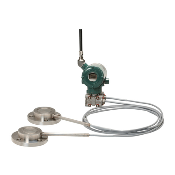
<3. Component Names> Component Names EJX118B EJX438B Transmitter Vent/drain plug Transmitter section * Flushing section * connection ring * See below for details * See below Capillary tube for details Diaphragm seal Cover flange with flushing connection ring Cover flange Diaphragm seal (high pressure side) Diaphragm seal... -
Page 21: Installation
<4. Installation> Installation Precautions Mounting the Diaphragm Seals Before installing the transmitter, read the cautionary notes in section 2.4, “Selecting the Installation Mount the diaphragm seals using the flanges as Location.” For additional information on the shown in Figure 4.1. Figure 4.2 and Figure 4.3 ambient conditions allowed at the installation shows how to mount the diaphragm seals on a location, refer to subsection 10.1 “Standard tank. The mating flange, gasket, bolts and nuts are... -
Page 22: Transmitter Mounting
<4. Installation> IMPORTANT pressure IMPORTANT side Install the sealed diaphragm • When measuring the liquid level of the tank, so that the shank positions the minimum liquid level (zero point) must downward. be set to a level at least 50 mm above the center of the high pressure side diaphragm seal (see Figure 4.2). - Page 23 <4. Installation> ■ When mounting the bracket on the transmitter, ■ When the transmitter can’t be installed at least tighten the (four) bolts that hold the transmitter 600 mm below the HP process connection. to a torque of approximately 39 N·m {4 kgf·m}. IMPORTANT IMPORTANT The transmitter should be installed at least • The transmitter should be installed at least 600 mm below the high pressure (HP) process 600 mm below the high pressure (HP)
-
Page 24: Mounting The Flushing Connection Ring
<4. Installation> Mounting the Flushing Connection Ring Low pressure side 4.4.1 Mounting to Pressure Detector Section The flushing connection ring is mounted to the pressure detector section as shown in Figure 4.7. High At the factory shipment, the flushing connection pressure side ring is already assembled and attached to process detector section. Pressure-detector section (–) F0405.ai Spiral gasket... -
Page 25: Affixing The Teflon Film
<4. Installation> IMPORTANT Spiral gasket 1) Position the diaphragm seal so that the Mating flange diaphragm is in a upward position. Ring 2) Pour the fluorinated oil on the diaphragm and gasket area covering it completely and evenly. Be careful not to scratch the diaphragm or change the its shape. 3) Affix the teflon film over the diaphragm and gasket area. -
Page 26: Changing The Direction Of Integral Indicator
<4. Installation> Changing the direction of The transmitter section can be rotated approximately 360° (180° to either direction or the antenna 360° to one direction from the original position at shipment, depending on the configuration of the Adjust the direction of the antenna to be in the instrument.) It can be fixed at any angle within upright position. -
Page 27: Wiring
<5. Wiring> Wiring Mounting Antenna and Wiring An antenna is not attached to the transmitter. The following provides the instructions for mounting the antenna and installing the remote antenna and wiring using antenna extension cable. IMPORTANT The antenna connector is covered with a cap at the time of delivery. -
Page 28: Mounting External Antenna And Wiring Antenna Extension Cable
<5. Wiring> 5.1.2 Mounting External Antenna and Mounting Procedure of External Wiring Antenna Extension Cable Antenna 1. Fix the bracket by U-bolt and nut to 50 mm (2- 5.1.2.1 Mounting of External Antenna inch) pipe. 2. Fix the antenna extension cable to the bracket Mount the external antenna at the proper location 1 using the provided nut with a torque of 6 to 7 according to the wireless environment described... - Page 29 Antenna extension cable 1: 3 m Antenna extension cable 1: 3 m Protect by self-bonding tape Transmitter body Transmitter body F0504.ai Figure 5.4 Wiring the antenna extension cable CAUTION Use the dedicated antenna extension cable provided by Yokogawa as accessories for the transmitters. IM 01C27H01-01EN...
-
Page 30: Mounting Of Arrester And Wiring
<5. Wiring> Grounding 5.1.2.3 Mounting of Arrester and Wiring Mount an arrester between the extension cables When using the antenna extension cable with an and connect the grounding cable to the grounding arrestor, Class C grounding with the grounding terminal of the arrester as required. resistance of 10 Ω is required. Always ground the transmitter case in accordance with national and Connect the grounding cable to the grounding... -
Page 31: Operation
<6. Operation> Operation Preparation for Starting Operation This section describes the operation procedure for the EJX118B as shown in Figure 6.1 when Diaphragm seal measuring liquid level in a closed tank, and EJX438B as shown in Figure 6.2 when measuring pressure in a tank. -
Page 32: Zero Point Adjustment
<6. Operation> ■ Confirm that transmitter is operating (1) When you can obtain the Low Range Value properly by integral indicator. from the actual measured value of 0% (0 kPa, atmospheric pressure); • If the transmitter is faulty, an error code is displayed. ■ Using the transmitter’s zero-adjustment screw Before adjusting zero point, make sure followings. -
Page 33: Starting Operation
<6. Operation> Connecting to the Field ■ Using the Device Configuration Tool Wireless Network Refer to subsection 7.3.14 “Zero-point Adjustment and Span Adjustment”. ■ Preparation work prior to connecting to a (2) When you cannot obtain the Low Range Field Wireless Network Value from the actual measured value of This transmitter does not need to be connected with a physical wire. - Page 34 When the Field Wireless Integrated Gateway is not transmitter glass window and the infrared device found and a specified time based on the silence should be within 30cm. For details of Yokogawa- mode has elapsed, a cycle of a one-hour pause and recommended infrared device, refer to subsection six-minutes search is repeated until the instrument 8.2 “Calibration Instruments Selection”.
-
Page 35: Shutting Down The Transmitter
<6. Operation> (a) Deep sleep NOTE If the transmitter searches the Field Wireless Network for long time at low ambient temperature condition, sometimes error “AL.70 LOWBAT” is displayed on the Integral Indicator. Even though using new batteries, it can occur. It occurs because of battery characteristics. -
Page 36: Draining Condensate For Flushing Connection Ring
<6. Operation> WARNING Since the accumulated liquid (or gas) may be toxic or otherwise harmful, take appropriate care to avoid contact with the body, or inhalation of vapors. 6.6.1 Draining Condensate for Flushing Connection Ring 1) Gradually open the drain screw to drain from the flushing connection ring.(See figure 6.7.) 2) When the flushing connection ring is completely drained, close the drain screw. -
Page 37: Setting Parameters
After setting and sending data with the field configuration tool. wireless configuration tool or the device Refer to the following website for the latest configuration tool, wait 30 seconds before information on CF/DD and DeviceDTM. turning off the transmitter. If it is turned off <http://www.yokogawa.com/> too soon, the settings will not be stored in the transmitter. IM 01C27H01-01EN... - Page 38 <7. Setting Parameters> Table 7.1 Parameter Usage and Selection Item Description Tag No. Sets the tag No. as Device Tag (Software Tag). Sixteen characters (alphanumeric characters, including - and •) can be set. Output The process variable and the diagnostic result can be output. Either or all of differential pressure (AI1:Process Value), static pressure (AI2:Process Value), temperature(AI3:Process Value) of capsule or amplifier and self-diagnostic information (UAPMO:Diagnostic Status) can be set to the output...
-
Page 39: Function Block And Menu Tree
<7. Setting Parameters> 7.3.2 Function Block and Menu Tree (1) Function Block The function of this transmitter is shown below. A specific function might not be able to be used according to the field wireless configuration tool used. When the field wireless configuration tool of our recommendation is used, the software attached to the Field Wireless Integrated Gateway is necessary for setting the dotted line part. Refer to Subsection 8.2 “Calibration Instruments Selection” for the field wireless configuration tool of our recommendation. Online Menu (UAPMO) (Configuration) • UAPMO • Configuration •... - Page 40 <7. Setting Parameters> Online Menu (continued) (AI1 DP) (Block Info) • Tag Description • Block Info • Block Mode • Dynamic Variables (Block Mode ) • Configuration • Mode.Target • Calibration • Mode.Actual • Others • Mode.Permitted • Mode.Normal (Process Value) (Dynamic Variables) •...
- Page 41 <7. Setting Parameters> Online Menu (continued) (AI2 SP) (Block Info) • Tag Description • Block Info • Block Mode • Dynamic Variables (Block Mode ) • Configuration • Mode.Target • Others • Mode.Actual • Mode.Permitted • Mode.Normal (Dynamic Variables) (Process Value) •...
- Page 42 <7. Setting Parameters> Online Menu (continued) (Block Info) (AI3 Temp) • Tag Description • Block Info • Block Mode • Dynamic Variables (Block Mode ) • Configuration • Mode.Target • Others • Mode.Actual • Mode.Permitted • Mode.Normal (Dynamic Variables) (Process Value) •...
- Page 43 <7. Setting Parameters> (2) Menu Tree The menu tree of the device configuration tool of our recommendation is shown below. Refer to Subsection 8.2 “Calibration Instruments Selection” for the device configuration tool of our recommendation. (Alerts) Menu (Online) (Device Configuration) (UAPMO) (Configuration) • Device Configuration • UAPMO • Configure/Setup • UAP Option • Other Faults Alert • Diagnostic • TRANSDUCER • Hardware Write Protect • Faults Non-compliance •...
- Page 44 <7. Setting Parameters> Menu (Online) Device Configuration (continued) (continued) (Block Info) (AI2 SP) • Configure/Setup • Tag Description (Block Mode) • Mode.Target • Mode.Actual • Mode.Permitted • Mode.Normal (Configuration) (Block Mode) • Block Mode • Mode.Target • Concentrator OID • Mode.Actual •...
- Page 45 <7. Setting Parameters> Menu (Online) (continued) (UAPMO) (Diagnostics) (Diagnostic) (Diagnostic Configuration) • UAPMO • Device Diagnostics • Diagnostic Status • Diagnostic.Other Faults • Diagnostic Status Detail.1 • Diagnostic.Faults Non-Compliance • Diagnostic Status Detail.2 • Diagnostic.Faults Process Influence • Diagnostic Switch •...
-
Page 46: Parameters For Wireless Communication
7-10 <7. Setting Parameters> 7.3.3 Parameters for Wireless (6) LCD display Communication The following steps describe how to set LCD display. (1) Network Information 1. On/Off of display Concentrator object block : Configuration When “Enable” in LCD Mode is selected, the Allows confirming the network information. LCD displays a set of screens to be shown and turns off for the specified time based on LCD (2) Update Time Intermittent Time, and the display keeps the... -
Page 47: Unit
7-11 <7. Setting Parameters> • When changing the device information, input 7.3.8 Output Signal Low Cut Mode Setup the information based on the following limitation Low cut mode can be used to stabilize the output on the number of characters. signal near the zero point. - Message function (up to 32 characters) ( There is 10% of hysteresis at only point of TRANSDUCER block : Tag Description... -
Page 48: Impulse Line Connection Orientation Setup
7-12 <7. Setting Parameters> 7.3.11 Integral Indicator Scale Setup The low cut point has hysterisis so that the output around the point is behaved as below figure. The following three displays are available for <Example> the integral indictor: differential pressure, static Output mode: Linear pressure, and temperature. The following three Low cut mode: Zero variables can be displayed on the integral indicator: % of differential pressure range, % of static... -
Page 49: Unit For Displayed Temperature
7-13 <7. Setting Parameters> 7.3.12 Unit for Displayed Temperature 7.3.14 Zero Point Adjustment and Span Adjustment When the instrument is shipped, the temperature units are set to C (Centigrade). Follow the Each EJX-B Series Differential Pressure/Pressure procedure below to change this setting. Transmitter is characterized by factory. - Page 50 7-14 <7. Setting Parameters> To match current input and output value, Using External Zero-adjustment Screw follow procedure External Zero-adjustment parameter (External Like tank level measurement that is impossible to Zero Trim) can set permission or prohibition to set actual level to zero, output value is adjustment adjustment by External Zero-adjustment Screw.
-
Page 51: Software Write Protect
7-15 <7. Setting Parameters> • Procedure to call up the calibration adjustment (4) Reset Adjustment parameter (Cal Cmd). Reset Adjustment clear the amount of adjustment. AI1 block : Cal Cmd : CAL_LOW Reset Ajustment can be performed using CAL_ Confirm the lower limit of the measurement CLEAR of the differential pressure (AI1 block) Cal Cmd parameter for the input pressure and using range in CAL_LOW of the differential pressure (AI1 block) Cal Cmd parameter. -
Page 52: Switching To Deep Sleep Mode
7-16 <7. Setting Parameters> 7.3.16 Switching to Deep Sleep Mode 7.3.17 Switching to Silence Mode When the instrument will not be used for a long This is a function to pause the instrument when time, switch the instrument to deep sleep mode to it cannot join the field wireless network after a conserve battery power. -
Page 53: Self-Diagnostics
7-17 <7. Setting Parameters> Self-Diagnostics UAPMO block: Diagnostic Status Any of the four categories (Check function, 7.4.1 Identify Problems by Using the Maintenance required, Failure, and Off Device Configuration Tool specification) according to NAMUR NE107* is supplied to Diagnostic Status of each diagnostic First, check Diagnostic Status of the self-diagnostic result. -
Page 54: Alert Report
7-18 <7. Setting Parameters> 7.4.2 Alert Report EJX generates alert information related to Diagnostic Status and automatically sends to a field wireless gateway. To use this function, the following alert setting is necessary. When “Out of Service” for Diagnostic Status alert is required, choose “FALSE” for [Out of Service.Alert Disable] in the UAPMO block. Refer to the field wireless gateway User’s Manual for the setting procedure to obtain the alert information from the gateway. - Page 55 7-19 <7. Setting Parameters> Table 7.5 Diagnostic Results Summary NAMUR Diagnostic Status Alert NE107 Diagnostic Status Detail Description Contents Type Category AMP_EEPROM_FAIL Amplifier EEPROM failure AMP_EEP_IRREGULAR AMP EEPROM version not correct G_A_COMM_FAIL G/A failure Faults in electronics FC_DELTA_T_FAIL C-side delta T circuit failure FR_DELTA_T_FAIL R-side delta T circuit failure Battery voltage not detected (AMP...
-
Page 56: Checking With Integral Indicator
7-20 <7. Setting Parameters> 7.4.3 Checking with Integral Indicator NOTE If an error is detected by running self-diagnostics, an error number is displayed on the integral indicator. If there is more than one error, the error number changes at three-second intervals. See Table 8.3 regarding the error codes. -
Page 57: Maintenance
<8. Maintenance> Maintenance Overview Calibration Use the procedure below to check instrument WARNING operation and accuracy during periodic maintenance or troubleshooting. Since the accumulated process fluid may be 1) Insert the battery pack and then perform toxic or otherwise harmful, take appropriate care provisioning to have the transmitter join the to avoid contact with the body or inhalation of field wireless network or preparing the infrared vapors when draining condensate or venting gas... - Page 58 <8. Maintenance> Table 8.1 Instruments Required for Calibration Name Yokogawa-recommended Instrument Remarks Provisioning • FieldMate (R2.02.01 or later) device tool • Provisioning Device Tool • Infrared Adapter certified by Yokogawa Supplier: ACTiSYS Product name: IrDA InfraRed USB Adaptor Product number: IR224UN Field wireless • Field Wireless Integrated Gateway attached Software configuration Field Wireless Configurator tool Field Wireless Management Tool • Field Wireless System related Product...
-
Page 59: Disassembly And Reassembly
<8. Maintenance> Disassembly and CAUTION Reassembly Always remove Battery pack and shut off CAUTION pressures before disassembly and assembly. Use proper tools for all operations. Precautions for the intrinsic safety explosion prevention type instrument 8.4.1 Replacing the Integral Indicator Intrinsic safe type transmitters must be, as This subsection describes the procedure for a rule, removed to a non-hazardous area replacing an integral indicator. (See figure 8.2) -
Page 60: Replacing The Rf Assembly
<8. Maintenance> 8.4.2 Replacing the RF Assembly 4) Use a socket driver (width across flats, 5.5 mm) to loosen the two bosses. This subsection describes how to replace the RF 5) Carefully pull the CPU assembly straight assembly (see Figure 8.2). forward to remove it. 6) Disconnect the flat cable (cable with white ■ Removing the RF assembly connector at the end) that connects the CPU 1) Remove the cover. -
Page 61: Replacing The Battery Pack
<8. Maintenance> 8.4.4 Replacing the Battery Pack 8.4.5 Replacing the Batteries Regarding the transmitter with intrinsically safe The batteries in the battery pack can be replaced. approval, the battery pack can be replaced without Batteries are not installed when shipped from the removing the device in hazardous area. -
Page 62: Handling Batteries
<8. Maintenance> 8.4.6 Handling Batteries ■ Transportation of products containing lithium batteries: This battery pack uses two primary lithium/ Batteries used for this transmitter contain thionyl chloride batteries. Each battery contains approximately 5 grams of lithium, for a total of 10 lithium. Primary lithium batteries are regulated in transportation by the U.S. -
Page 63: Troubleshooting
Abnormalities appear in measurement. use the troubleshooting flow chart below to isolate and remedy the problem. Since some problems have complex causes, these flow charts may Is process variable not identify all. If you have difficulty isolating or itself abnormal? correcting a problem, contact Yokogawa service personnel. Inspect the Measurement system problem process system. 8.5.1 Basic Troubleshooting First determine whether the process variable... -
Page 64: Troubleshooting Flowcharts
Is the Field Wireless Network Is zero point setting correct? adjusted correctly? Reconnect to the Field Wireless Network. Adjust the zero point. Contact Yokogawa service personnel. Contact Yokogawa service personnel. F0807.ai F0806.ai IM 01C27H01-01EN... - Page 65 Provide lagging and/or heat insulation, or allow adequate ventilation. Were appropriate instruments used for calibration? Refer to 8.2 “Calibration Instruments Selection”. Is output adjusted correctly? Adjust the output. Contact Yokogawa service personnel. F0808.ai IM 01C27H01-01EN...
-
Page 66: Errors And Countermeasures
8-10 <8. Maintenance> 8.5.3 Errors and Countermeasures Table 8.3 Error Message Summary (Causes and Actions) Release/ Factory recovery Integral NAMUR Diagnostic Diagnostic Status Detail Cause conditions Action indicator category Status (except restart) FC_SENSOR_FAIL Recovers only when AUTO FR_SENSOR_FAIL RECOVER is ON and within the range Pressure sensor... - Page 67 8-11 <8. Maintenance> Release/ Factory recovery Integral NAMUR Diagnostic Diagnostic Status Detail Cause conditions Action indicator category Status (except restart) DP_TRIM_SPAN_OUTSIDE Pressure span Recovers Check adjustment when span the span AL.53 variable outside adjustment adjustment P. ADJ of range variable/point variable for returns within the Pressure.
- Page 68 8-12 <8. Maintenance> Release/ Factory recovery Integral NAMUR Diagnostic Diagnostic Status Detail Cause conditions Action indicator category Status (except restart) SimulationActive AI1 block is Returns when Check the (AI1) simulate mode. the simulate simulate AL. 63 mode of AI1 mode of AI1 AI SIM block is set block.
- Page 69 8-13 <8. Maintenance> Table 8.4 Error Message Summary (Output Actions) Output actions Factory Integral Diagnostic Capsule NAMUR Diagnostic Status Detail Static Indicator Status Pressure Temp Temp category Pressure Value Value FC_SENSOR_FAIL Output value Output value (hold value) (hold value) FR_SENSOR_FAIL Output status Output status Normal action...
- Page 70 8-14 <8. Maintenance> Output actions Factory Integral Diagnostic Capsule NAMUR Diagnostic Status Detail Static Indicator Status Pressure Temp Temp category Pressure Value Value DP_OUTSIDE_LIMIT Output value Output value (calculated in (calculated in a normal way) a normal way) AL. 10 Output status Output status Normal action Normal action...
- Page 71 8-15 <8. Maintenance> Output actions Factory Integral Diagnostic Capsule NAMUR Diagnostic Status Detail Static Indicator Status Pressure Temp Temp category Pressure Value Value AL. 30 Environmental DP_OUTSIDE_RANGE Normal action Normal action Normal action Normal action RANGE conditions out Bit 22 of device SP_OUTSIDE_RANGE AL.
-
Page 72: Parameter Summary
<9. Parameter Summary> Parameter Summary Table 9.1 Parameter Object Attribute Default Label Description Handling value Version Revision Indicates the application revision of EJX This revision UAPMO when the application software is downloaded. block Static Revision Indicates the revision level of the fixed parameters of UAP Used, for example, to check whether parameters have been change. - Page 73 <9. Parameter Summary> Object Attribute Default Label Description Handling value Power Supply Indicates the predicted battery level and the power UAPMO Status supply method. block 0 = external power supply (continued) 1 = battery level 75% or more 2 = battery level 25% ~ 75% 3 = battery level 25% or less EHType Available to write note into this parameter.
- Page 74 <9. Parameter Summary> Object Attribute Default Label Description Handling value Faults Sensor or The On/Off or priority for Faults Sensor or actuator 1. TRUE UAPMO actuator Alert Alert can be set. 2. 15 block 1. On/Off setting (continued) 0 = FALSE, 255 =TRUE 2.
- Page 75 <9. Parameter Summary> Object Attribute Default Label Description Handling value PUB_ITEM_MAX Maximum PUB_ITEM value PUB_ITEM_NUM PUB_ITEM number block PUB_ITEM Indicates the PUB_ITEM information. The following (continued) shows the components 1. ObjectID 2. AttributeID 3. AttributeIndex 4. Size Tag Description Memo field available to write anything. Transducer TRANSDUCER Auto Recovery...
- Page 76 <9. Parameter Summary> Object Attribute Default Label Description Handling value Special Order ID Displays the special order number, if applicable. TRANSDUCER Unit Sel1 Selects whether to automatically apply the unit to the Auto block word for the parameter for which the unit display is (continued) selected, or apply the characters that are written to Display Unit1.
- Page 77 <9. Parameter Summary> Object Attribute Default Label Description Handling value Lower Limit Indicates the lower limit (LRL) for the pressure. PV Range Sets the measurement range. EU at 100% block 1. EU at 100% : Indicates input value of the upper = 100 (continued) limit.
- Page 78 <9. Parameter Summary> Object Attribute Default Label Description Handling value T Zero Cmp Parameter to select the temperature zero shift compensation mode block 0 = OFF : Does not perform temperature zero shift (continued) compensation. 1 = ON : Performs temperature zero shift compensation.
- Page 79 <9. Parameter Summary> Object Attribute Default Label Description Handling value PV Range Sets the measurement range. 1. EU at 1. EU at 100% : Indicates input value of the upper 100% = block limit. 25000.000000 (continued) 2. EU at 0% : Indicates input value of the lower limit. EU at 0% 3.
- Page 80 <9. Parameter Summary> Object Attribute Default Label Description Handling value Block Mode A universal parameter to indicate the block’s operation 1. Target = status. O/S, Auto, and Man can be selected. Auto block 1. Target : Specify Al object mode. 2.
- Page 81 9-10 <9. Parameter Summary> Table 9.2 Diagnostic Status Detail[0] Diagnostic Status Diagnostic Status Detail Description NAMUR assignment bit DiagnosticDetail_1 FC_SENSOR_FAIL C sensor frequency error Bit26 FR_SENSOR_FAIL R sensor frequency error Bit26 CAP_T_SENSOR_FAIL Capsule temperature sensor failure Bit26 CAP_EEPROM_FAIL Capsule EEPROM failure Bit26 CAP_EEP_IRREGULAR CAP EEPROM version not correct...
-
Page 82: General Specifications
10-1 <10. General Specifications> 10. General Specifications 10.1 Standard Specifications Power Supply Specifications Battery: Use the dedicated battery pack. Communication protocol Rated voltage: 7.2 V ISA100.11a protocol Rated capacity: 19 Ah Data rate Output 250 kbps Wireless (ISA100.11a protocol) 2.4 GHz signal. Output mode for EJX118B, linear or square Frequency root, is selectable. - Page 83 Note: The differential pressure transmitter should be installed at least 600 mm below the high pressure (HP) process connection. However, this value (600 mm) may be affected by ambient temperature, operating pressure, fill fluid or material of the wetted diaphragm. Contact YOKOGAWA when the transmitter can not be installed at least 600 mm below the HP process connection.. Process temperature...
- Page 84 10-3 <10. General Specifications> EMC Conformity Standards Gasket Contact Surface EN61326-1 Class A, Table 2 (For use in See the following table. industrial locations), EN61326-2-3 Table 10.3 Gasket contact surface Immunity influence during the test Flange JIS/JPI/DIN ANSI Differential pressure/ pressure: Output shift is Wetted parts material code specified within ±1% of 1/10 Max span.
- Page 85 10-4 <10. General Specifications> Weight EJX118B Flush type: 18.2 kg (40.1 lbs) (3-inch ANSI Class150 flange, capillary length 5 m; without integral indicator and mounting bracket.) Extended type: 23.8 kg (52.5 lbs) (4-inch ANSI Class150 flange, extension length )=100 mm, capillary length 5 m; without integral indicator and mounting bracket.) Combination type: 21.0 kg (46.3 lbs) (4-inch and 3-inch ANSI Class150 flange, extension length (X ) =100 mm, capillary length...
-
Page 86: Model And Suffix Codes
10-5 <10. General Specifications> 10.2 Model and Suffix Codes Instruction The model and suffix codes for EJX118B and EJX438B consist of two parts; a transmitter body section (I) and a diaphragm seal section (II). This specification sheet introduces these two parts separately. The transmitter body section is shown in one table, and the diaphragm seal section specifications are listed according to the process connection style. First select the model and suffix codes of transmitter body section and then continue on one of the diaphragm seal section. EJX118B EJX438B I Transmitter body section II Diaphragm seal section F1003.ai I. Transmitter body section EJX118B EJX438B Model Suffix codes Description EJX118B ........Diaphragm sealed differential pressure transmitter EJX438B . - Page 87 10-6 <10. General Specifications> Diaphragm seal section (Flush type) Process connection size: 3-inch (80 mm) / 2-inch (50 mm) EJX118B EJX438B F1004.ai Model Suffix codes Description EJX118B ....Transmitter body section (I) EJX438B Process connection style...
- Page 88 10-7 <10. General Specifications> *6: In case of wetted parts material code HW (Hastelloy C), TW (Tantalum), and UW (Titanium) for 2-inch pressure flange, specify capillary length from 1 to 5 m. *7: Not applicable for flashing connection ring code 1 and 2. Not applicable for gasket contact surface code 1. Hastelloy C-276 or N10276. *10: Users must consider the characteristics of selected wetted parts material and the influence of process fluids. The use of inappropriate materials can result in the leakage of corrosive process fluids and cause injury to personnel and/or damage to plant facilities. It is also possible that the diaphragm itself can be damaged and that material from the broken diaphragm and the fill fluid can contaminate the user’s process fluids. Be very careful with highly corrosive process fluids such as hydrochloric acid, sulfuric acid, hydrogen sulfide, sodium hypochlorite, and high-temperature steam (150˚C [302˚F] or above). Contact Yokogawa for detailed information of the wetted parts material. IM 01C27H01-01E...
- Page 89 See table 10.3 ‘Gasket contact surface.’ *2: When specified flushing connection ring code 3, 4, C, or D, exclusive gasket is provided for transmitter side. *3: Even in case where fill fluid code D (fluorinated oil) is selected, if degrease cleansing treatment or both degrease cleansing and dehydrating treatment for the wetted parts is required, specify option code K1 or K5. Not applicable for gasket contact surface code 1. Users must consider the characteristics of selected wetted parts material and the influence of process fluids. The use of inappropriate materials can result in the leakage of corrosive process fluids and cause injury to personnel and/or damage to plant facilities. It is also possible that the diaphragm itself can be damaged and that material from the broken diaphragm and the fill fluid can contaminate the user’s process fluids. Be very careful with highly corrosive process fluids such as hydrochloric acid, sulfuric acid, hydrogen sulfide, sodium hypochlorite, and high-temperature steam (150˚C [302˚F] or above). Contact Yokogawa for detailed information of the wetted parts material. IM 01C27H01-01E...
- Page 90 Option codes / Optional specification T12E.ai The “►” marks indicate the most typical selection for each specification. Example: EJX118B-LMSCG-98JDN-EA14B1SE02-BB25/ EJX438B-LASCG-98JDN-EA14B1SE01-BB25/ See table 10.3 ‘Gasket contact surface.’ *2: Even in case where fill fluid code D (fluorinated oil) is selected, if degrease cleansing treatment or both degrease cleansing and dehydrating treatment for the wetted parts is required, specify option code K1 or K5. *3: The specified capillary length includes the extension length (X2) and the flange thickness (t). Users must consider the characteristics of selected wetted parts material and the influence of process fluids. The use of inappropriate materials can result in the leakage of corrosive process fluids and cause injury to personnel and/or damage to plant facilities. It is also possible that the diaphragm itself can be damaged and that material from the broken diaphragm and the fill fluid can contaminate the user’s process fluids. Be very careful with highly corrosive process fluids such as hydrochloric acid, sulfuric acid, hydrogen sulfide, sodium hypochlorite, and high-temperature steam (150˚C [302˚F] or above). Contact Yokogawa for detailed information of the wetted parts material. IM 01C27H01-01E...
- Page 91 K1 or K5. *3: The specified capillary length of high pressure side (extended side) includes the extension length (X2) and the flange thickness (t). Users must consider the characteristics of selected wetted parts material and the influence of process fluids. The use of inappropriate materials can result in the leakage of corrosive process fluids and cause injury to personnel and/or damage to plant facilities. It is also possible that the diaphragm itself can be damaged and that material from the broken diaphragm and the fill fluid can contaminate the user’s process fluids. Be very careful with highly corrosive process fluids such as hydrochloric acid, sulfuric acid, hydrogen sulfide, sodium hypochlorite, and high-temperature steam (150°C [302°F] or above). Contact Yokogawa for detailed information of the wetted parts material. IM 01C27H01-01E...
-
Page 92: Optional Specifications
10-11 <10. General Specifications> 10.3 Optional Specifications OPTIONAL SPECIFICATIONS (For Explosion Protected type) Item Description Code Factory Mutual (FM) FM Intrinsically safe Approval FS17 ATEX ATEX Intrinsically safe Approval KS27 Canadian Standards Association (CSA) CSA Intrinsically safe Approval CS17 IECEx IECEx Intrinsically safe Approval SS27 ... - Page 93 Alternatively, Tadiran SL-2780/S or TL-5930/S batteries can be purchased from your local distributor. If you need F9915NS, please purchase F9915NK. F9915NK is a set of F9915NS and instruction manual. Use of high gain antenna is limited by local regulation of radio and telecommunication law. Consult Yokogawa for details. IM 01C27H01-01E...
-
Page 94: Dimensions
10-13 <10. General Specifications> 10.4 Dimensions Unit: mm (approx. inch) <Transmitter body section> (Amplifier housing code 8) For EJX118B For EJX438B 191 (7.52) 122 (4.80) (0.94) Zero adjustment Integral indicator (1.61) (2.52) (1.54) For electrical Open to connection code Ground terminal (5.51) atmosphere 5, 9, A, and D... - Page 95 10-14 <10. General Specifications> Unit: mm (approx. inch) Extended type Extension length øD Extension code øC 50(1.97) øg 100(3.94) øA 150(5.91) n-øh Capillary length ø30 (ø1.18) Combination type for EJX118B øD øC øg n-øh (0.98) øA *3*4 n-øh ød Capillary ø30 length...
- Page 96 10-15 <10. General Specifications> Unit: mm (Approx.: inch) Process flange size: 4 inch (100 mm) Bolt holes *3 *4 Code Flange rating øD øC øg ød øA No.(n) Dia.(øh) JIS 10K 210 (8.27) 175 (6.89) 155 (6.10) — 18 (0.71) 19 (0.75) —...
- Page 97 10-16 <10. General Specifications> Infrared Configuration Infrared port F1010.ai IM 01C27H01-01E...
-
Page 98: Revision Information
Revision Information Title : EJX118B and EJX438B Diaphragm Sealed Differential Pressure and Pressure Transmitters Manual No. : IM 01C27H01-01EN Edition Date Page Revised Item Aug. 2010 — Release of ISA100.11a protocol Apr. 2011 — • Adapted to device configuration tool with infrared communication function. • Part number change Battery pack: F9915MA →...
Need help?
Do you have a question about the DP Harp EJX118B and is the answer not in the manual?
Questions and answers