YOKOGAWA DPharp EJX110A User Manual
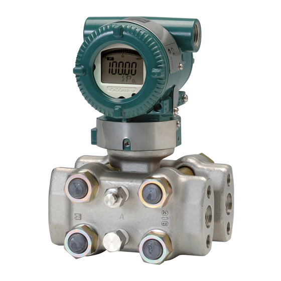
Differential pressure and pressure transmitters
Hide thumbs
Also See for DPharp EJX110A:
- User manual (66 pages) ,
- Installation manual (57 pages) ,
- Installation manual (60 pages)

Related Manuals for YOKOGAWA DPharp EJX110A


Summary of Contents for YOKOGAWA DPharp EJX110A
- Page 1 User’s Manual EJX110A, EJX120A, EJX130A, EJX310A, EJX430A, and EJX440A Differential Pressure and Pressure Transmitters IM 01C25B01-01E IM 01C25B01-01E 10th Edition...
-
Page 2: Table Of Contents
Rotating Pressure-detector Section 180° ......... 4-3 4.4.2 Using the Communicator ..............4-3 Rotating Transmitter Section ................4-4 Changing the Direction of Integral Indicator ..........4-4 10th Edition: Apr. 2010 (YK) IM 01C25B01-01E All Rights Reserved, Copyright © 2004, Yokogawa Electric Corporation... - Page 3 Installing Impulse Piping ................. 5-1 Impulse Piping Installation Precautions ............5-1 5.1.1 Connecting Impulse Piping to a Transmitter ........5-1 5.1.2 Routing the Impulse Piping ..............5-3 Impulse Piping Connection Examples ............5-4 Wiring ......................6-1 Wiring Precautions ................... 6-1 Selecting the Wiring Materials .................
- Page 4 8.5 Troubleshooting ....................8-6 8.5.1 Basic Troubleshooting ............... 8-6 8.5.2 Troubleshooting Flowcharts ............... 8-7 8.5.3 Alarms and Countermeasures ............8-9 General Specifications ................9-1 9.1 Standard Specifications ................... 9-1 9.2 Model and Suffix Codes ................... 9-5 9.3 Optional Specifications ................. 9-12 Dimensions ...................... 9-15 Revision Information When using the EJX in a Safety Instrumented Systems(SIS) application, refer to Appendix A in either IM 01C25T01-01E for the HART protocol or IM 01C25T03-01E for the BRAIN protocol.
-
Page 5: Introduction
For FOUNDATION Fieldbus protocol type, written permission. please refer to IM 01C25T02-01E. • Yokogawa makes no warranty of any kind with To ensure correct use of this instrument, read regard to this manual, including, but not limited both the hardware and software manuals to, implied warranty of merchantability and thoroughly before use. -
Page 6: Safe Use Of This Product
If these instructions are not heeded, injury. the protection provided by this instrument may be impaired. In this case, Yokogawa cannot guarantee that the instrument can be safely operated. Please CAUTION pay special attention to the following points:... -
Page 7: Warranty
(f) Modification • Yokogawa will not be liable for malfunctions or - Improper and/or inadequate maintenance by damage resulting from any modification made the purchaser. to this instrument by the customer. -
Page 8: Atex Documentation
<1. Introduction> ATEX Documentation This is only applicable to the countries in European Union. IM 01C25B01-01E... -
Page 9: Handling Cautions
<2. Handling Cautions> Handling Cautions 2.1 Model and Specifications This chapter provides important information on how to handle the transmitter. Read this carefully before Check using the transmitter. The model name and specifications are written on EJX Series transmitters are thoroughly tested at the the name plate attached to the case. factory before shipment. -
Page 10: Selecting The Installation Location
<2. Handling Cautions> Selecting the Installation The following precautions must be observed in order to safely operate the transmitter under Location pressure. The transmitter is designed to withstand severe (a) Make sure that all the process connector bolts environmental conditions. However, to ensure are tightened firmly. -
Page 11: Installation Of An Explosion-Protected Instrument
Please 2) Turn OFF the insulation tester. Then connect contact Yokogawa before making any repair or the insulation tester plus (+) lead wire to the modification to an instrument. shorted SUPPLY terminals and the minus (–) leadwire to the grounding terminal. - Page 12 Ci = 6 nF replacement by other than authorized Imax = 200 mA Li = 0 µH representative of Yokogawa Electric Pmax = 1 W Corporation is prohibited and will void Factory Mutual Intrinsically safe and * Associated Apparatus Parameters Nonincendive Approval.
-
Page 13: Csa Certification
• The instrument modification or parts CAN/CSA E60079-11, CAN/CSA E60079-15, replacement by other than authorized IEC 60529:2001-02 representative of Yokogawa Electric • Ex ia IIC T4, Ex nL IIC T4 Corporation is prohibited and will void • Ambient Temperature: –50* to 60°C Factory Mutual Explosionproof Approval. - Page 14 • The instrument modification or parts • Supply Voltage: 42 V dc max. replacement by other than authorized • Output Signal: 4 to 20 mA dc representative of Yokogawa Electric Note 2. Wiring Corporation and Yokogawa Corporation • All wiring shall comply with Canadian...
- Page 15 T120°C (Tamb.: –40* to 60°C, Tp.: 120°C) * –15°C when /HE is specified. replacement by other than authorized representative of Yokogawa Electric • Enclosure: IP66 and IP67 Corporation and Yokogawa Corporation of Note 2. Electrical Data America is prohibited and will void Canadian • In type of explosion protection intrinsic Standards Explosionproof Certification.
- Page 16 * –15°C when /HE is specified. • The instrument modification or parts • Maximum Process Temperature (Tp.) for replacement by other than authorized gas-proof: representative of Yokogawa Electric 85°C (T6), 100°C (T5), and 120°C (T4) Corporation is prohibited and will void KEMA • Maximum Surface Temperature for dust- Intrinsically safe Certification.
- Page 17 (4) Operation Note 3. Maintenance and Repair WARNING • The instrument modification or parts replacement by other than authorized representative of Yokogawa Electric • OPEN CIRCUIT BEFORE REMOVING Corporation is prohibited and will void Type COVER. INSTALL IN ACCORDANCE WITH of Protection “n”. THIS USER’S MANUAL •...
-
Page 18: Iecex Certification
The instrument modification or parts replacement Model EJX Series pressure transmitters with by other than an authorized Representative of optional code /SU2 can be selected the type of Yokogawa Electric Corporation is prohibited and protection (IECEx Intrinsically Safe/type n or will void the certification. flameproof) for use in hazardous locations. Note 1. For the installation of this transmitter,... -
Page 19: Emc Conformity Standards
IECEx Flameproof Type Caution for IECEx flameproof type. CAUTION Note 1. Model EJX Series pressure transmitters To meet EMC regulations, Yokogawa with optional code /SF2 or /SU2 are recommends that customers run signal applicable for use in hazardous locations: wiring through metal conduits or use shielded •... -
Page 20: Low Voltage Directive
2-12 <2. Handling Cautions> (3) Operation • EJX110A-MS, EJX110A-HS, EJX110A-VS, EJX130A, EJX440A, CAUTION EJX510A-D, and EJX530A-D can be used above 200 bar and therefore considered as • The temperature and pressure of fluid should a part of a pressure retaining vessel where category III, Module H applies. These models be maintained at levels that are consistent with option code /PE3 conform to that category.
Need help?
Do you have a question about the DPharp EJX110A and is the answer not in the manual?
Questions and answers