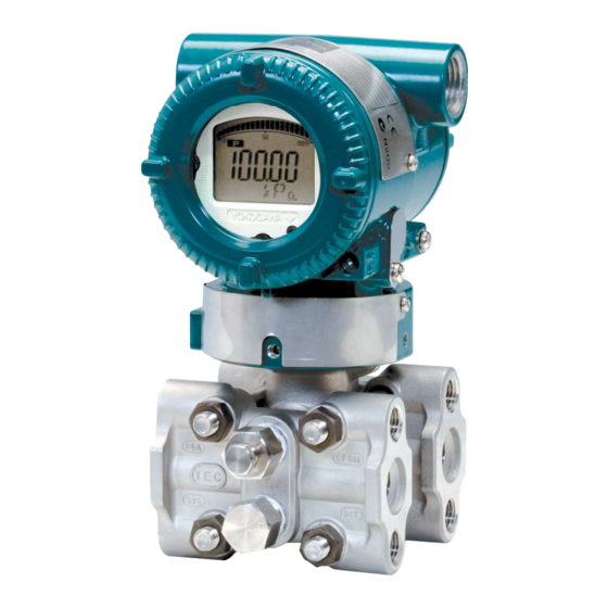
YOKOGAWA DPharp EJX Series Installation Manual

YOKOGAWA DPharp EJX Series Installation Manual

Differential pressure and pressure transmitters
Hide thumbs Also See for DPharp EJX Series:

Advertisement

User's
Manual
EJX and EJA-E Series
Differential Pressure and
Pressure Transmitters
Installation Manual
Contents
1.
1.1
1.2
2.
3.
3.1
3.2
4.
5.
5.1
5.3
5.5
6.
6.1
7.
For Safe Use of Product ..............................................3
Warranty ......................................................................5
.................................7
..................................................7
..................................... 31
................................................... 32
................................ 33
Mounting................................................................... 34
......................................34
............................................. 37
.................................... 38
Wiring Precautions ................................................... 44
Wiring ....................................................................... 47
Grounding ................................................................ 51
Preparation for Starting Operation ........................... 52
.............................................. 52
.......................................... 53
..............................7
......7
...................... 31
............ 35
.................. 36
............. 38
................... 39
..................... 42
115
42
...... 44
......... 49
........... 51

Advertisement

Table of Contents
loading
Need help?

Need help?

Do you have a question about the DPharp EJX Series and is the answer not in the manual?

Questions and answers

Subscribe to Our Youtube Channel

Summary of Contents for YOKOGAWA DPharp EJX Series

  • Page 1: Table Of Contents

    User’s Manual EJX and EJA-E Series Differential Pressure and Pressure Transmitters Installation Manual Contents Introduction For Safe Use of Product ..........3 Warranty ..............5 Handling Cautions .........7 ......7 ..........7 ..7 ........31 ...... 31 ........... 32 ........ 33 Installation Mounting..............34 ........34 ....
  • Page 2: Introduction

    <1. Introduction> Introduction Table 1.1 PDF Manual List and Applicable Style Code [EJX series Hardware Manual] Models Document No. Style — WARNING — [EJX series Communication Manual] Models Document No. Style — — operating it. — — — — — [EJA-E series Hardware Manual] Models Document No.
  • Page 3 <1. Introduction> Regarding This Manual Model Document No. purpose. WARNING CAUTION IM 01C25A01-01E...
  • Page 4: For Safe Use Of Product

    <1. Introduction> (b) Wiring IMPORTANT WARNING NOTE operators. (c) Operation WARNING For Safe Use of Product (d) Maintenance WARNING (a) Installation WARNING (e) Explosion Protected Type Instrument for operators. WARNING location. IM 01C25A01-01E...
  • Page 5 <1. Introduction> WARNING (g) Product Disposal (h) Authorized Representative in EEA Control of Pollution Caused by the Product Cr(VI) PBDE × × Series × × GB/T26572 GB/T26572 SJ /T11364 Morocco conformity mark IM 01C25A01-01E...
  • Page 6: Warranty

    <1. Introduction> Warranty installation location. Trademarks: IM 01C25A01-01E...
  • Page 7: Handling Cautions

    <2. Handling Cautions> Handling Cautions EJX910A EJX930A included. EJ 210 Table 2.1 Applicable Model Code for Mounting Hardware EJ 510 Applicable Part name EJ 530 model EJX610A EJX630A Process Process connector connections EJ 118 Process connector EJ 438 Process Process connector connections EJ 115 Process connector...
  • Page 8 <2. Handling Cautions> Pressure Connection Check WARNING F0203.ai Figure 2.2 Name Plate Selecting the Installation Location piping. Installation of an Explosion- Protected Instrument location. CAUTION WARNING IM 01C25A01-01E...
  • Page 9 Groups A, B, C, D, F, G Class III, Division 1 Class I, Zone 2, Group IIC General Purpo se EJX Series Equipment Pressure Transmitter Suppl (Refer to Note 4) Rev.2: July 16, 2019 Doc. No.: IFM022-A12 Yokogawa Electric Corpor ation IM 01C25A01-01E...
  • Page 10 Model: EJX-F Series Date: January 27, 2005 Rev.3: July 16, 2019 Doc. No.: IFM022-A12 Yokogawa Electric Corpor ation Control drawing (intrinsic safety) FM Intrinsically Safe/Nonincendive for Fieldbus Type (Except for EJX9 0A) locations. Clas s I, II, III, Divis ion 1...
  • Page 11 AND SU ITABILITY FOR HAZARDOUS LOCATION Rev.4: July 16, 2019 Doc. No.: IFM024 -A12 Rev.1: July 16, 2019 Doc. No.: IFM024 -A12 Yokogawa Electric Corpor ation Yokogawa Electric Corpor ation IFM024 IFM024 Model: EJX-F Series Date: May 9, 2006 Model: EJX-F Series...
  • Page 12 Rev.2: July 16, 2019 Doc. No.: IFM024-A12 P.4-2 Clas s I, II, III, Divis ion 1 Yokogawa Electric Corpor ation IFM024 Groups A, B, C, D , E, F, G Clas s I, Zone 0 , Group IIC FM Intrinsically Safe/Nonincendive for...
  • Page 13 Rev.2: July 16, 2019 Doc. No.: IFM026 -A12 Rev.1: July 16, 2019 Doc. No.: IFM026 -A12 P.3-1 Yokogawa Electric Corpor ation Yokogawa Electric Corpor ation IFM026 IFM026 Model: EJX910A-F Series Date: September 9, 2005 Model: EJX910A-F Series Date: May 22, 2006...
  • Page 14 SUPPLY Three-Wire Connection Pressure Transmitters SUPPLY Voltmeter Power Supply – – SUPPLY Rev.1: July 16, 2019 Doc. No.: IFM026-A12 P.3-3 Four-Wire Connection Yokogawa Electric Corpor ation F0218.ai IFM026 • FM Explosionproof • • • • • • • IM 01C25A01-01E...
  • Page 15 <2. Handling Cautions> FM Intrinsically Safe and Explosion Proof • Combination for HART/BRAIN Protocol Type • • • • • • • • • CSA Intrinsically Safe for HART/BRAIN Protocol Type (Except for EJX9 0A) • • • • IM 01C25A01-01E...
  • Page 16 <2. Handling Cautions> • [Intrinsically Safe] Hazardous Location Nonhazardous Location Group IIC, Zone 0 Class I, II, III, Division 1, General Groups A, B, C, D, E, F, G Purpose Safety Barrier Pressure Transmitters Equipment – – – Supply – F0206.ai [Nonincendive] Hazardous Location...
  • Page 17 <2. Handling Cautions> Electrical Data: Caution for CSA Non-incendive Type. (Following contents refer to “DOC. No. ICS018) Installation Diagram for Non-incendive or Type of protection “n” (Division 2 Installation) Terminator SUPPLY – Pressure Transmitter Transmitter – Transmitter – Hazardous location Non-Hazardous location Terminator –...
  • Page 18 <2. Handling Cautions> CSA Explosionproof Type Non-Hazardous Hazardous Locations Division 1 Locations Non-hazardous 45 cm Max. Location Equipment 42 V DC Max. Conduit Sealing Fitting 4 to 20 mA DC • Signal Transmitter F0208.ai Non-Hazardous Hazardous Locations Division 2 Locations Non-hazardous Location Equipment 42 V DC Max.
  • Page 19 <2. Handling Cautions> • (1) Technical Data ATEX Intrinsically Safe for HART/BRAIN Protocol Type (Except for EJX9 0A) • • • • • • • • CSA Intrinsically Safe and Explosion-proof Combination for HART/BRAIN Protocol Type (Except for EJX9 0A) •...
  • Page 20 <2. Handling Cautions> ATEX Intrinsically Safe for Fieldbus Type (Except for EJX9 0A) [Control Drawing] Hazardous Location Nonhazardous Location Pressure Transmitters Safety Barrier *1 Supply – WARNING F0210.ai • NOTE conditions of use. WARNING Ambient Process temperature range temperature range 6 or later Maximum Ambient...
  • Page 21 <2. Handling Cautions> Screw Size Marking ISO M20 × 1.5 female ANSI 1/2 NPT female A or N or F0239.ai IM 01C25A01-01E...
  • Page 22 <2. Handling Cautions> ATEX Intrinsically Safe for Fieldbus Type for EJX9 0A WARNING [Installation Diagram] Terminator Pt100.3wire Pressure SUPPLY Transmitter Transmitter Transmitter Hazardous Location Non-Hazardous Location Terminator Safety Barrier F0232.ai IM 01C25A01-01E...
  • Page 23 <2. Handling Cautions> ATEX Flameproof Type Supply circuit • • • Sensor circuit IM 01C25A01-01E...
  • Page 24 <2. Handling Cautions> • WARNING • conductor. • Pressure Transmitters SUPPLY Voltmeter Power Supply – – SUPPLY Three-Wire Connection Pressure Transmitters SUPPLY Voltmeter Power Supply – – ATEX Intrinsically Safe and ATEX SUPPLY Flameproof Combination for HART/BRAIN Four-Wire Connection Protocol Type (Except for EJX9 0A) F0220.ai •...
  • Page 25 <2. Handling Cautions> ATEX Intrinsically Safe Ex ic for Fieldbus ATEX Intrinsically Safe Ex ic Type (Except for EJX9 0A) Ambient Process Type of O-ring temperature range temperature range Screw Size Marking ISO M20 × 1.5 female ANSI 1/2 NPT female A or N or F0239.ai...
  • Page 26 <2. Handling Cautions> (3) Installation WARNING (4) Operation WARNING (5) Maintenance and Repair WARNING (2) Electrical Connection Screw Size Marking ISO M20 × 1.5 female ANSI 1/2 NPT female N or Location of the mark F0214.ai IM 01C25A01-01E...
  • Page 27 <2. Handling Cautions> (6) Name Plate Tag plate for intrinsically safe Ex ic for Fieldbus Ex ic IIC T4 Gc Name plate IP66 Tamb -30(-15) TO 60°C MAX. PROCESS TEMP. 120°C Ui=32V, Ci=3.52nF, Li=0µH WARNING POTENTIAL ELECTROSTATIC CHARGING HAZARD - SEE USER'S MANUAL. Tag plate for flameproof type [EJX9 0A] Ex db IIC T6...T4 Gb...
  • Page 28 <2. Handling Cautions> locations. [Ex ia] Hazardous Location Nonhazardous Location Group IIC, Zone 0 IECEx certified EJX/EJA-E Series Safety Barrier Pressure Transmitters – – Supply (*1) *1: When using non isolation barrier, connect (*1) to IS barrier system. F0236.ai WARNING IECEx Intrinsically Safe Ex ia for HART/ BRAIN Protocol Type (Except for EJX9 0A) IECEx Intrinsically Safe Ex ic for HART/...
  • Page 29 <2. Handling Cautions> IECEx Intrinsically Safe Ex ia for Fieldbus Type (Except for EJX9 0A) WARNING NOTE [Ex ic] Hazardous Location Nonhazardous Location EJX/EJA-E Series Associated apparatus conditions of use. Pressure Transmitters Supply – – F0237.ai WARNING Ambient Process temperature range temperature range 5 or later IM 01C25A01-01E...
  • Page 30 <2. Handling Cautions> Screw Size Marking ISO M20 × 1.5 female A or N or ANSI 1/2 NPT female F0239.ai IM 01C25A01-01E...
  • Page 31 <2. Handling Cautions> IECEx Intrinsically Safe Ex ic for Fieldbus Type (Except for EJX9 0A) WARNING NOTE conditions of use. Ambient Process Type of O-ring temperature range temperature range IECEx Flameproof Type Screw Size Marking ISO M20 × 1.5 female ANSI 1/2 NPT female A or N or...
  • Page 32 <2. Handling Cautions> • • Screw Size Marking ISO M20 × 1.5 female ANSI 1/2 NPT female N or Location of the mark F0222.ai Pressure Transmitters SUPPLY EMC Conformity Standards Voltmeter Power Supply – – SUPPLY CAUTION Three-Wire Connection Pressure Transmitters SUPPLY Voltmeter Power Supply...
  • Page 33 <2. Handling Cautions> (2) Technical Data (3) Operation CAUTION PS.V Model code conditions. EU RoHS Directive AAnnnnnnn IM 01C25A01-01E...
  • Page 34 <2. Handling Cautions> Safety Requirement Standards (1) Pollution Degree 2 (2) Installation Category I (3) Indoor/Outdoor use (4) Altitude of installation site IM 01C25A01-01E...
  • Page 35: Installation

    <3. Installation> Installation Vertical pipe mounting Vertical pipe mounting IMPORTANT (Process connector upside) (Process connector downside) Mounting bracket 50 mm (2-inch) pipe U-bolt nut U-bolt Transmitter mounting bolt F0303.ai not face upward. Figure 3.3 Transmitter Mounting (Vertical Impulse Piping Type) Vertical pipe mounting Horizontal pipe mounting Pipe...
  • Page 36 <3. Installation> Diaphragm Seals Installation 3.2.1 EJ 210 Consideration IMPORTANT Gasket Stud bolt F0305.ai Figure 3.5 EJ 210 Mounting 3.2.2 EJ 118 and EJ 438 IMPORTANT pressure Flange side Diaphragm Bolt Install the sealed diaphragm so that the shank positions downward.
  • Page 37 <3. Installation> Low pressure side IMPORTANT High pressure side (P–P0) (–) × 0.102 [mm] F0308.ai Figure 3.8 Example of Installation to Tank (Caution on Installation) Mounting the Flushing Connection Ring 3.4.1 Mounting to Pressure Detector Wetted parts Process connection size Capillary Section material...
  • Page 38 <3. Installation> 3.4.2 Mounting to Process Flange IMPORTANT Spiral gasket Mating flange is in an upward position. Ring area. Diaphragm Gasket Pressure-detector section F0310.ai Teflon film Figure 3.10 Mounting to Process Flange PART No. EJ 210 F9347YD 2 inch EJ 118 F9347YA IMPORTANT EJ 438...
  • Page 39 <3. Installation> Rotating Transmitter Section Changing the Direction of Integral Indicator IMPORTANT designated position. WARNING F0313.ai Figure 3.13 Integral Indicator Direction IMPORTANT IMPORTANT Vertical impulse piping type Pressure-detector section Stopper Conduit connection Transmitter section Horizontal impulse piping type Transmitter section CPU assembly 90°...
  • Page 40: Installing Impulse Piping

    <4. Installing Impulse Piping> Installing Impulse Piping Impulse Piping Installation (3) Tightening the Process Connector Mounting Bolts Precautions IMPORTANT 4.1.1 Connecting Impulse Piping to the Transmitter (4) Removing the Impulse Piping Connecting (1) Check the High and Low Pressure Port Dustproof Cap Connections on the Transmitter (Figure 4.1) (5) Connecting the Transmitter and 3-Valve Differential Pressure Transmitter...
  • Page 41 <4. Installing Impulse Piping> Pipe-Mounting Type 3-Valve Manifold Direct-Mounting Type 3-Valve Manifold Impulse piping Nipple Vent plug 3-valve (optional) manifold Ball head lock nut Stop valve (low pressure side) Pipe Pipes Equalizing valve Impulse Bolts (balancing) piping Process Stop valve Ball head connector 3-valve...
  • Page 42 <4. Installing Impulse Piping> 4.1.2 Routing the Impulse Piping (4) Temperature Difference Between Impulse Piping (for differential pressure (1) Process Pressure Tap Angles transmitters) (5) Condensate Pots for Steam Flow NOTE Measurement (for differential pressure transmitters) [Gas] [Liquid] [Steam] (6) Preventing Wind Speed Effects in Very Low 45°...
  • Page 43 <4. Installing Impulse Piping> Impulse Piping Connection Liquid Steam Examples Tap valve Union or flange Union or flange Tap valve Drain plug Drain valve Union or flange Union or flange Tap valve Drain valve Drain valve Drain plug Drain plug F0408.ai conditions.
  • Page 44 <4. Installing Impulse Piping> (2) Tightening the Process Connector (3) Preventing Freezing Mounting Bolts (4) Process Piping Connection Examples IMPORTANT (3) Removing the Process Connector Port Dustproof Cap conditions. 4.3.2 Routing the Process Piping application. (1) Relationship between Process Fluid Union or flange Gas flow measurement and Manifold Locations (For the vertical...
  • Page 45: Wiring

    <5. Wiring> Wiring Connections of External NOTE Wiring to Terminal Box For F RTD cable connection* Wiring Precautions IMPORTANT Terminal [B]* Terminal Terminal Terminal wiring. *For EJX9 A only. F0527.ai Power supply and output terminals SUPPLY – External indicator (ammeter) terminals CHECK *1*2 –...
  • Page 46 <5. Wiring> 5.2.1 Power Supply Wiring Connection 5.2.3 Status Output Connection IMPORTANT Transmitter 24V DC terminal box Shielded cable Distributor – Transmitter terminal box Magnetic Power supply valve External power – supply 30V DC, 120mA max Load resistance is not F0502.ai Use two-wire separately shielded cables.
  • Page 47 <5. Wiring> 5.2.4 Connection Example for EJX910A and EJX930A Table 5.1 The connection example for simultaneous analog and pulse and alarm, status output. (For HART protocol type) Description Connection Analog Output Transmitter Electrical Terminal Distributor In this case, 24V DC SUPPLY Communication is –...
  • Page 48: Wiring

    <5. Wiring> 5.2.5 External Temperature Connection • Pulse output and Alarm, Status Output or (for EJX910A and EJX930A) Simultaneous Analog-Pulse Output (for EJX910A and EJX930A) Hazardous Location Nonhazardous Location Transmitter terminal box Distributor (Power supply unit) Receiver instrument F0505.ai Figure 5.8 External Temperature Connection Wiring Receiver...
  • Page 49 <5. Wiring> • Simultaneous Analog-Pulse Output • Four wire connection Hazardous Location Nonhazardous Location Transmitter terminal box I/O module Hazardous Location Nonhazardous Location Safety barrier (Isolated type) Transmitter terminal box Distributor Power (Power supply unit) supply Analog input Power supply Receiver instrument Pulse input...
  • Page 50 <5. Wiring> (2) Flameproof Type Electrical connection Cable gland RTD cable with connector Flameproof packing Detail of connector adapter Transmitter Flexible metal conduit Wiring metal F0514.ai Apply a non-hardening conduit sealant to the threads for waterproofing. Drain plug F0512.ai Figure 5.16 Typical Cable Wiring Using Flameproof Packing Adapter Protection Cap...
  • Page 51 <5. Wiring> Procedure CAUTION connection. 5.4.2 Connecting Shielded Cable for Con- duit Use (External temperature input code: -B, -C, and -D) F0517.ai F0518.ai F0522.ai Procedure F0519.ai F0523.ai F0520.ai CAUTION F0521.ai IM 01C25A01-01E...
  • Page 52: Grounding

    <5. Wiring> Grounding 5.4.3 Cable Connection RTD Terminal Box Side type. NOTE Ground terminal (inside) CAUTION Ground terminal (outside) F0525.ai Figure 5.19 Ground Terminals insulation or its core. Power Supply Voltage and Load Resistance 2-Wire 3-Wire 4-Wire B b A E–10.5 External F0524.ai...
  • Page 53: Operation

    <6. Operation> Operation NOTE Burnout direction switch For F BO H Slide switch WR E Write protection switch CPU assembly Burnout direction switch (BO) Burnout Direction Preparation for Starting Switch Position Operation Burnout Direction HIGH Hardware write protection switch (WR) Write Protection Properly Switch Position...
  • Page 54 <6. Operation> Local Parameter Setting WARNING location. IMPORTANT 6.2.2 Adjusting Zero Point for Gauge/ Absolute Pressure Transmitters setting. (1) When you can obtain the Low Range Value from the actual measured value of 0% (0 kPa, atmospheric pressure); procedure. 6.3.1 Local Parameter Setting (LPS) Overview is carried out.
  • Page 55 <6. Operation> screw Process Zero adjustment Measurement Display push Activate LPS mode push 1. Loop Test Select Output Current Run/Cancel 2. Tag Number Edit Tag number Save/Cancel the value push 3. Press Unit Select Press unit Save/Cancel the value 4. Press LRV Edit Press LRV Save/Cancel the value push...
  • Page 56: Errors And Countermeasures

    <7. Errors and Countermeasures> Errors and Countermeasures NOTE Table 7.1 Alarm Message Summary (Except EJX910A and EJX930A) Output Operation Indicator Cause Countermeasure during Error None AL. 01 CAP. ERR AL. 02 AMP. ERR AL. 10 PRESS necessary. AL. 11 ST. PRSS AL.
  • Page 57 <7. Errors and Countermeasures> Table 7.2 Alarm Message Summary (For EJX910A and EJX930A, HART protocol type) Integral 4-20mA Output Cause Countermeasure indicator operation during error AL. 01 CAP.ERR AL. 02 AMP.ERR AL. 03 ET.ERR disconnection. — AL. 10 PRESS necessary. AL.
  • Page 58 <7. Errors and Countermeasures> Integral 4-20mA Output Cause Countermeasure indicator operation during error AL. 79 OV. DISP needed. AL.87 FLG. HI setting. AL.87 FLG. LO AL.88 INVR.DP out. AL.88 INVR.SL AL.88 INVR.SH AL.88 INVR.F AL.89 ILBD.OV AL.89 B BLK detected. setting.
  • Page 59 Revision Information Page 7 to 14 41 to 43 13 to 14 16 and 17 28 to 34 5.2.1 Add note for power supply. 37 to 42 16 to 17 6.3.11 IM 01C25A01-01E...
  • Page 60 Page 7 to 28 26 to 31 for code Z. 8 to 12 16 to 23 safe type. 8 to 13 IM 01C25A01-01E...

Table of Contents