Advertisement
Quick Links
User's
Manual
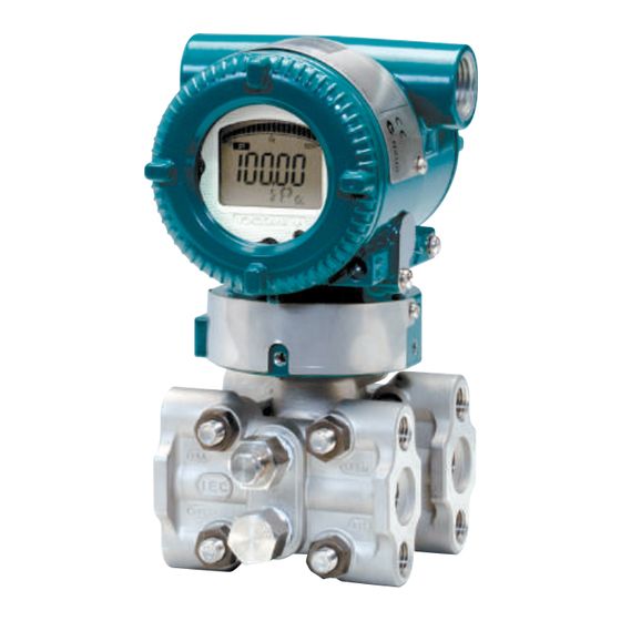
EJX and EJA-E Series
Differential Pressure and
Pressure Transmitters
Installation Manual
Contents
1.
Introduction
1.1
1.2
2.
Handling Cautions
2.1
2.2
2.3
2.4
2.5
2.6
2.7
2.8
3.
Installation
3.1
3.2
3.3
3.4
3.5
3.6
3.7
4.
Installing Impulse Piping
4.1
4.2
4.3
5.
Wiring
5.1
5.2
5.3
5.4
5.5
5.6
6.
Operation
6.1
6.2
6.3
7.
Errors and Countermeasures
IM 01C25A01-01E
For Safe Use of Product ..............................................3
Warranty ......................................................................5
Model and Specifications Check .................................7
Selecting the Installation Location ..............................7
Pressure Connection ..................................................7
Installation of an Explosion-Protected Instrument ......8
EMC Conformity Standards ..................................... 33
Pressure Equipment Directive (PED) ...................... 33
EU RoHS Directive ................................................... 34
Safety Requirement Standards ................................ 34
Mounting................................................................... 35
Mounting the Diaphragm Seals ......................................37
Diaphragm Seals Installation Consideration ............ 38
Mounting the Flushing Connection Ring .................. 39
Affixing the Teflon Film ............................................. 40
Rotating Transmitter Section .................................... 41
Changing the Direction of Integral Indicator............. 41
Impulse Piping Installation Precautions ................... 42
Impulse Piping Connection Examples ..................... 45
Process Piping Installation Precautions (EJ115) 45
Wiring Precautions ................................................... 47
Connections of External Wiring to Terminal Box ...... 47
Wiring ....................................................................... 50
RTD Cable Connection (EJX910A/EJX930A) ......... 52
Grounding ................................................................ 56
Power Supply Voltage and Load Resistance ........... 56
Preparation for Starting Operation ........................... 57
Zero Point Adjustment .............................................. 57
Local Parameter Setting .......................................... 58
IM 01C25A01-01E
16th Edition
Advertisement

Subscribe to Our Youtube Channel
Related Manuals for YOKOGAWA DP harp EJX Series


Summary of Contents for YOKOGAWA DP harp EJX Series
- Page 1 User’s Manual EJX and EJA-E Series Differential Pressure and Pressure Transmitters Installation Manual IM 01C25A01-01E Contents Introduction For Safe Use of Product ..........3 Warranty ..............5 Handling Cautions 2.1 Model and Specifications Check .........7 2.2 Selecting the Installation Location ......7 2.3 Pressure Connection ..........7 2.4 Installation of an Explosion-Protected Instrument ..8 2.5 EMC Conformity Standards ........33 2.6 Pressure Equipment Directive (PED) ......
- Page 2 EJX910A and EJX930A including safety manual for safety instrumented system. IM 01C25R03-01E — Fieldbus Communication Type The specifications of each product including external EJX910A and EJX930A Modbus dimensions and detailed model and suffx codes are IM 01C25R05-01E — Communication Type described in General Specifications sheet(GS.) [EJA-E series Hardware Manual] These manuals and GSs can be downloaded from the Models Document No. Style website of Yokogawa, and printed manuals can also be EJA110E, EJA120E purchased from the Yokogawa representatives. IM 01C25B01-01E S1,S2 EJA130E, EJA310E, EJA430E Website address: and EJA440E https://www.yokogawa.com/solutions/products-platforms/field-instruments/ EJA210E IM 01C25C01-01E S1,S2 EJA510E and EJA530E IM 01C25F01-01E S1,S2 EJA118E and EJA438E IM 01C25H01-01E S1,S2...
- Page 3 GS 01C25B01-01EN • The contents of this manual are subject to change EJX120A GS 01C25B03-01EN without prior notice. EJX130A GS 01C25B04-01EN • All rights reserved. No part of this manual may be EJX210A GS 01C25C01-01EN reproduced in any form without Yokogawa’s written EJX310A GS 01C25D01-01EN permission. EJX430A GS 01C25E01-01EN EJX440A GS 01C25E02-01EN • Yokogawa makes no warranty of any kind with regard EJX510A, EJX530A GS 01C25F01-01EN to this manual, including, but not limited to, implied EJX610A, EJX630A GS 01C25F05-01EN warranty of merchantability and fitness for a particular EJX118A GS 01C25H01-01EN purpose. EJX118A GS 01C25H01-11EN • If any question arises or errors are found, or if any EJX438A GS 01C25J03-01EN information is missing from this manual, please inform EJX438A GS 01C25J03-11EN the nearest Yokogawa sales office.
- Page 4 • Wait 5 min. after power is turned off, before in order to avoid the risk of injury or death of opening the covers. personnel or damage to the instrument. • Do not open the cover in wet weather or humid environment. If the cover is opened, stated For Safe Use of Product enclosure protection is not applicable. For the protection and safety of the operator and the (d) Maintenance instrument or the system including the instrument, please be sure to follow the instructions on safety described in this manual when handling this instrument. In case WARNING the instrument is handled in contradiction to these instructions, Yokogawa does not guarantee safety. • Please do not carry out except being written Please give your attention to the followings. to maintenance descriptions. When these procedures are needed, please contact nearest (a) Installation YOKOGAWA office. • Care should be taken to prevent the build up of WARNING drift, dust or other material on the display glass and name plate. In case of its maintenance, soft and dry cloth is used. • The instrument must be installed by an expert engineer or a skilled personnel. The procedures described about INSTALLATION are not permitted (e) Explosion Protected Type Instrument for operators.
- Page 5 <1. Introduction> (f) Modification WARNING • Yokogawa will not be liable for malfunctions or damage resulting from any modification made to this instrument by the customer. (g) Product Disposal The instrument should be disposed of in accordance with local and national legislation/regulations. (h) Authorized Representative in EEA and the importer into the EU/EEA market In relation to the CE Marking, The authorized representative for this product in the EEA (European Economic Area) is: Yokogawa Europe B.V. Euroweg 2, 3825 HD Amersfoort,The Netherlands and the importer for this product into the EU/EEA market via the YOKOGAWA sales channel is: Yokogawa Europe B.V. Euroweg 2, 3825 HD Amersfoort,The Netherlands Control of Pollution Caused by the Product This is an explanation for the product based on “Control...
- Page 6 <1. Introduction> Warranty • The warranty shall cover the period noted on the quotation presented to the purchaser at the time of purchase. Problems occurred during the warranty period shall basically be repaired free of charge. • In case of problems, the customer should contact the Yokogawa representative from which the instrument was purchased, or the nearest Yokogawa office. • If a problem arises with this instrument, please inform us of the nature of the problem and the circumstances under which it developed, including the model specification and serial number. Any diagrams, data and other information you can include in your communication will also be helpful. • Responsible party for repair cost for the problems shall be determined by Yokogawa based on our investigation. • The Purchaser shall bear the responsibility for repair costs, even during the warranty period, if the malfunction is due to: - Improper and/or inadequate maintenance by the purchaser. - Failure or damage due to improper handling, use or storage which is out of design conditions. - Use of the product in question in a location not conforming to the standards specified by Yokogawa, or due to improper maintenance of the installation location. - Failure or damage due to modification or repair by any party except Yokogawa or an approved representative of Yokogawa.
- Page 7 <2. Handling Cautions> Handling Cautions When the transmitter is delivered, visually check them Applicable Suffix code Part name to make sure that no damage occurred during shipment. model Also check that all transmitter mounting hardware shown U-bolt EJ110 in Figure 2.1 is included. If the transmitter was ordered U-bolt nut EJ120 without the mounting bracket or without the process Mounting bracket EJ130 (L or flat type) EJ310 connector, the transmitter mounting hardware is not Mounting bracket EJ430 Plate included. EJ440 Position adjusting EJ115 Table 2.1 Applicable Model Code for Mounting screw Hardware EJX910A...
- Page 8 <2. Handling Cautions> Selecting the Installation Cable gland and RTD cable (EJX910A and EJX930A only) Location Bolt The transmitter is designed to withstand severe environmental conditions. However, to ensure that it will provide years of stable and accurate performance, take Process connector the following precautions when selecting the installation location. Process connector Gasket (a) Ambient Temperature U-bolt Avoid locations subject to wide temperature variations or a significant temperature gradient. If the location is exposed to direct sunlight or radiant heat from plant equipment, provide adequate shade, thermal insulation and/or ventilation. Mounting bracket (Flat type) (b) Ambient Atmosphere Mounting bracket Do not install the transmitter in a corrosive (L type) atmosphere. If this cannot be avoided, there must be...
- Page 9 Installation of an Explosion- IMPORTANT Protected Instrument All the blind plugs which accompany the EJX/EJA-E If a customer makes a repair or modification to an transmitters upon shipment from the factory are intrinsically safe or explosionproof instrument and the certified by the applicable agency in combination with instrument is not restored to its original condition, its those transmitters. The plugs which are marked with intrinsically safe or explosionproof construction may be the symbols “◊ Ex” on their surfaces are certified only compromised and the instrument may be hazardous to in combination with the EJX/EJA-E series transmitters. operate. Please contact Yokogawa before making any repair or modification to an instrument. 2.4.1 FM Approval CAUTION FM Intrinsically Safe/Nonincendive for This instrument has been tested and certified as being HART/BRAIN Protocol Type (Except for intrinsically safe or explosionproof. Please note that EJX90A) severe restrictions (e.g. IEC 60079-14) apply to this instrument’s construction, installation, external wiring, Note 1. EJX/EJA-E Series pressure transmitters with maintenance and repair. A failure to abide by these optional code /FS1 are applicable for use in restrictions could make the instrument a hazard to hazardous locations.
- Page 10 Groups A, B, C, D, F, G T4 Class III Division 1 T4 Class I, Zone 2 Group IIC T4 • Ambient temperature: –55 to 60 °C Rev.2: July 16, 2019 Doc. No.: IFM022-A12 • Enclosure: Type 4X Yokogawa Electric Corporation • Electrical Connection: 1/2 NPT female, M20 female Model: EJX Series Date: October 22, 2003 Note 2. Installation Specific conditions of use: Installation should be in accordance with Control Precautions shall be taken to minimize the risk from electrostatic discharge of painted parts.
- Page 11 Groups A, B, C, D, E, F, G Class I, Zone 0, Group IIC Associated Apparatus (Safety Barrier) Rev.1: July 16, 2019 Doc. No.: IFM024-A12 P.2-1 Yokogawa Electric Corporation IFM024 Rev.1: July 16, 2019 Doc. No.: IFM024-A12 Yokogawa Electric Corporation Model: EJX-F Series Date: January 27, 2005...
- Page 12 Division 2 Groups A, B, C, D, F, G T4 Class III Division 1 T4 Class I, Zone 2 Group IIC T4 • Ambient temperature: –40 to 60°C Rev.5: July 16, 2019 Doc. No.: IFM024-A12 P.4-1 • Enclosure: Type 4X Yokogawa Electric Corporation IFM024 • Electrical Connection: 1/2 NPT female, M20 female Model: EJX-F Series Date: August 19, 2005 Note 2. Installation FNICO Rules Installation should be in accordance with Control The FNICO Concept allows the interconnection of nonincendive field wiring apparatus to associated nonincendive field wiring apparatus not specifically examined in such combination.
- Page 13 C = 0 ..2.2 μF Rev.1: July 16, 2019 Doc. No.: IFM026-A12 Rev.2: July 16, 2019 Doc. No.: IFM026-A12 Yokogawa Electric Corporation Yokogawa Electric Corporation IFM026 IFM026 Model: EJX910A-F Series Date: September 9, 2005 Model: EJX910A-F Series Date: May 22, 2006...
- Page 14 • Output signal: 4 to 20 mA 15 mA (F Fieldbus and PROFIBUS PA OUNDATION Rev.3: July 16, 2019 Doc. No.: IFM026-A12 P.3-2 type) Yokogawa Electric Corporation IFM026 1 to 5 V (Low Power type) RS485 Modbus (RS485 Modbus Communication Type) Model: EJX910A-F Series Date: May 22, 2006 FNICO Rules Note 2. Wiring The FNICO Concept allows the interconnection of nonincendive field wiring apparatus to associated nonincendive field wiring apparatus not specifically examined in such combination.
- Page 15 • Nonincendive for Class I, Division 2, Groups A, B, devices in a hazardous location. C & D, Class II, Division 2, Groups F & G, Class III, Division 1 Note 4. Maintenance and Repair • Enclosure: Type 4X • The instrument modification or parts replacement • Temp. Code: T4 by other than authorized representative of • Amb. Temp.: –50* to 60°C Yokogawa Electric Corporation is prohibited and * –15°C when /HE is specified. will void Factory Mutual Explosionproof Approval. • Process Temperature: 120°C max. [For Zone system] FM Intrinsically Safe and Explosion Proof • Ex ia IIC T4, Ex nL IIC T4 Combination for HART/BRAIN Protocol • Ambient Temperature: –50 to 60°C Type • Max. Process Temp.: 120°C EJX/EJA-E Series pressure transmitters with •...
- Page 16 <2. Handling Cautions> • The instrument modification or parts replacement • CSA Intrinsically Safe Approval by other than authorized representative of Class I, Division 1, Groups A, B, C, & D; Class II, Yokogawa Electric Corporation and Yokogawa Division 1, Groups E, F & G; Class III; Ex ia IIC T4 Corporation of America is prohibited and will Ambient Temperature: –55* to 60 °C * –15°C when /HE is specified. void Canadian Standards Intrinsically safe and Type 4X, IP66/IP67 nonincendive Certification. • CSA Nonincendive Approval [Intrinsically Safe] Class I, Division 2, Groups A, B, C, & D; Class II, Hazardous Location Nonhazardous Location Division 2, Groups F & G; Class III; Ex nL IIC T4 Group IIC, Zone 0 Ambient Temperature: –55* to 60 °C Class I, II, III, Division 1, General * –15°C when /HE is specified.
- Page 17 <2. Handling Cautions> Electrical Data: Caution for CSA Non-incendive Type. (Following contents refer to “DOC. No. • Rating 1 (Entity) ICS018) For Groups A, B, C, D, E, F, and G or Group IIC Ui (vmax) = 24 V dc Installation Diagram for Non-incendive or Type of Ii (Imax) = 250 mA protection “n” (Division 2 Installation) Pi (Pmax) = 1.2 W Terminator Ci = 3.52 nF Li = 0 μH SUPPLY – Pressure • Rating 2 (FISCO) Transmitter...
- Page 18 <2. Handling Cautions> CSA Explosionproof Type Non-Hazardous Hazardous Locations Division 1 Locations Caution for CSA explosionproof type. Non-hazardous 45 cm Max. Location Equipment Note 1. EJX/EJA-E Series pressure transmitters with optional code /CF1 or /V1F are applicable for use in hazardous locations. 42 V DC Max. • Certificate: 2014354 Conduit Sealing Fitting 4 to 20 mA DC • Applicable Standard: Signal Transmitter C22.2 No. 25 F0208.ai...
- Page 19 EN IEC 60079-0, EN 60079-11 when accessing to the instrument and peripheral • Certificate number: DEKRA 11ATEX0228 X devices in a hazardous location. • Specific Ex marking: II 1 G Ex ia IIC T4 Ga Note 4. Maintenance and Repair II 2 D Ex ia IIIC T85°C T100°C T120°C Db • The instrument modification or parts replacement • Ambient temperature: by other than authorized representative of EPL Ga −50°C ≤ Ta ≤ +60°C Yokogawa Electric Corporation and Yokogawa EPL Db −30°C ≤ Ta ≤ +60°C Corporation of America is prohibited and will void EPL Db * −15°C ≤ Ta ≤ +60°C Canadian Standards Explosionproof Certification. • Process temperature: CSA Intrinsically Safe and Explosion-proof EPL Ga −50°C ≤ Tp ≤ +120°C Combination for HART/BRAIN Protocol EPL Db T120°C −30°C ≤ Tp ≤ +120°C...
- Page 20 KEMA 04ATEX1116 X explosive atmospheres may be present, it must be installed in such a way that the risk from electrostatic NOTE discharges and propagating brush discharges caused by rapid flow of dust are avoided. The symbol “X” placed after the certificate number Note 5. Maintenance and repair indicates that the equipment is subject to specific conditions of use. WARNING Applicable Standard: A modification of the equipment would no longer EN IEC 60079-0 comply with the construction described in the EN 60079-11 certificate documentation. Only personnel authorized by Yokogawa Electric Note 2. Rating Corporation can repair the equipment. Ex Marking: II 2 G Ex ia IIC/IIB T4 Ga II 2 D Ex ia IIIC T85°C T100°C T120°C Db Yokogawa Electric Corporation EJX Series Model Control drawing (General) Title Temperature Specifications: IKE045-A91 2020-08-07 Page Revision Date Ambient Temperature range and Process...
- Page 21 <2. Handling Cautions> Enclosure: Note 6. Maintenance and Repair: IP66/IP67 in accordance with only EN60529 • Only personnel authorized by Yokogawa Electric Electrical Parameters: Corporation can repair the equipment. Intrinsically safe ratings are as follows: Note7. Control drawing [Entity] Ui = 24 V Ii = 250 mA Pi = 1.2 W Ci = 3.52 nF Li = 0 μH [FISCO IIC] Ui = 17.5 V Ii = 380 mA Pi = 5.32 W Ci = 3.52 nF Li = 0 μH [FISCO IIB] Ui = 17.5 V Ii = 460 mA Pi = 5.32 W Ci = 3.52 nF Li = 0 μH Note 3. Installation: • Refer to the control drawing IKE022-A12 P.1 and P.2. (Note 7.) • The type of threads is indicated at the cable entry, using the following marking.
- Page 22 P P t t 1 1 0 0 0 0 , , 3 3 w w i i r r e e from electrostatic discharges or propagating brush discharges on the non-metallic parts (excluding glass parts) or coated parts of the equipment. The dielectric strength of at least 500 V of the intrinsically safe circuits of the equipment is limited only by the overvoltage protection. From the safety point of view, the intrinsically safe circuit of the equipment shall be assumed to be connected to earth. Rev. Doc. No.: IKE032-A12 P.1 Drawing: M.Takeuchi Approved: H. Sugiyama Yokogawa Electric Corporation IKE032 IM 01C25A01-01E...
- Page 23 Rev.1: December 14, 2006 M.Takeuchi Doc. No.: IKE032-A12 P.2 Rev.2: October 15, 2011 T.Itou Drawing: M. Takeuchi • In order to prevent the earthing conductor from Approved: H. Sugiyama loosening, the conductor must be secured to the Yokogawa Electric Corporation IKE032 terminal, tightening the screw with appropriate torque. Care must be taken not to twist the ATEX Flameproof Type conductor. Caution for ATEX flameproof type. • Cable glands, adapters and/or blanking elements with a suitable IP rating shall be of Ex d IIC/Ex tb Note 1. EJX/EJA-E Series pressure transmitters with IIIC certified by ATEX and shall be installed so as...
- Page 24 Note 1. For the installation of this transmitter, once a devices in a hazardous location. particular type of protection is selected, any other type of protection cannot be used. The Note 6. Maintenance and Repair installation must be in accordance with the • Warning:When maintenance and repair are description about the type of protection in this performed, confirm the following conditions and user’s manual. the then perform works. Confirm the power supply is cut off and the voltage Note 2. For combined approval types of power supply terminal is not supplied. Once a device of multiple approval type is • Only personnel authorized by Yokogawa installed, it should not be re-installed using any Electric Corporation can repair the equipment other approval types. Apply a permanent mark in accordance with the relevant standards: IEC in the check box of the selected approval type / EN 60079-19 (Equipment repair, overhaul and on the certification label on the transmitter to reclamation) and IEC / EN 60079-17 (Electrical distinguish it from unused approval types. installation inspection and maintenance); ATEX Intrinsically Safe Ex ic otherwise the certification will be voided. Caution for ATEX intrinsically safe Ex ic Note 7. Specific Conditions of Use • Applicable standards:...
- Page 25 Screw Size Marking Only personnel authorized by Yokogawa Electric Corporation can repair the equipment. ISO M20 × 1.5 female ANSI 1/2 NPT female A or N or Yokogawa Electric Corporation EJX Series Model F0239.ai M. Inatomi Prepared by Control drawing Title D. Harada Approved by IKE046-A70...
- Page 26 <2. Handling Cautions> (3) Name Plate Note 7. Control drawing Name plate Tag plate for flameproof type No. KEMA 07ATEX0109 X Enlcosure : IP66/IP67 Ex db IIC T6...T4 Gb TEMP. CLASS PROCESS TEMP.(Tp.) -50 TO 85 120 °C Tamb. -50 TO 75 75 °C ...
- Page 27 <2. Handling Cautions> 2.4.4 IECEx Certification Tag plate for intrinsically safe Ex ic for Fieldbus Ex ic IIC T4 Gc Model EJX Series pressure transmitters with optional IP66 Tamb -30(-15) TO 60°C MAX. PROCESS TEMP. 120°C code /SU21 or /SU22 can be selected the type of Ui=32V, Ci=3.52nF, Li=0µH protection (IECEx Intrinsically Safe Ex ia, Ex ic or flameproof) for use in hazardous locations. WARNING EJX Series pressure transmitters with optional code /SS26 can be selected the type of protection (IECEx intrinsically safe Ex ia or Ex ic) for use in hazardous POTENTIAL ELECTROSTATIC CHARGING HAZARD - SEE USER'S MANUAL.
- Page 28 <2. Handling Cautions> Note 2. Specific condition of use Yokogawa Electric Corporation EJX Series Model Control drawing (General) When the equipment is mounted in an area where Title IKE045-A91 2020-08-07 Page Revision Date the use of EPL Ga equipment is required, it shall be installed in such a way that, even in the event of rare incidents, an ignition source due to impact and/or Hazardous Area Non−Hazardous Area friction sparks is excluded. Associated Transmitter Precaution shall be taken to minimize the risk Apparatus SUPPLY+ from electrostatic discharges or propagating brush SUPPLY− discharges on the non-metallic parts (excluding glass (Note 1) parts) or coated parts of the equipment. The dielectric strength of at least 500 V of the Ui= 30 V Ii= 200 mA intrinsically safe circuits of the equipment is limited Pi= 0.9 W...
- Page 29 • Applicable Standard • Cable glands, adapters and/or blanking elements IEC 60079-0 shall be of Ex “n”, Ex “e” or Ex “d” and shall be IEC 60079-11 installed so as to maintain the specified degree of protection of the equipment. Note 2. Rating • The instrument modification or parts replacement Ex Marking: by other than authorized representative of Ex ia IIC/IIB T4 Ga Yokogawa Electric Corporation is prohibited and Temperature specifications: will void IECEx certification. Ambient Temperature range and Process Temperature range for Gas: [Ex ic] Ambient temperature range Process temperature range Hazardous Location Nonhazardous Location –55 to 60°C –55 to 120°C EJX/EJA-E Series Associated apparatus...
- Page 30 • When the pressure transmitter is made of aluminum alloy, if it is mounted in an area where the use of EPL Ga equipment is required, it shall be installed such that, even in the event of rareincidents, an ignition source due to impact and friction sparks is excluded. • Precautions shall be taken to minimize the risk from electrostatic discharge of painted parts. • The dielectric strength of at least 500 V of the intrinsically safe circuits of the pressure transmitter is limited only by the overvoltage protection. Note 6. Maintenance and Repair • Only personnel authorized by Yokogawa Electric Corporation can repair the equipment. Note7. Control drawing IECEx Intrinsically Safe Ex ic for Fieldbus Type (Except for EJX90A) Caution for IECEx Intrinsically safe Ex ic. Note 1. EJX/EJA-E Series pressure transmitters with optional code /SS26 are applicable for use in hazardous locations. Certification Information: WARNING A modification of the equipment would no longer comply with the construction described in the certificate documentation.
- Page 31 Note 1. EJX/EJA-E Series pressure transmitters with from electrostatic discharges and propagating optional code /SF2 or /SU21 are applicable for brush discharges caused by rapid flow of dust are use in hazardous locations: avoided. • No. IECEx CSA 07.0008 Note 5. Specific conditions of use • Applicable Standard: IEC60079-0:2011, • See control drawing IIE020-A70 (Note 7.) IEC60079-1:2007-4 • Flameproof for Zone 1, Ex d IIC T6...T4 Gb Note 6. Maintenance and Repair • Enclosure: IP66/IP67 • Only personnel authorized by Yokogawa Electric • Maximum Process Temperature: 120°C (T4), Corporation can repair the equipment. 100°C (T5), 85°C (T6) • Ambient Temperature: –50 to 75°C (T4), –50 to 80°C (T5), –50 to 75°C (T6) • Supply Voltage: 42 V dc max. 32 V dc max. (F Fieldbus and OUNDATION PROFIBUS PA type) 9 to 28 V dc, 27 mW (Low Power type) 9 to 30 V dc, 250 mW (RS485 Modbus Communication Type) •...
- Page 32 • Maximum Surface Temperature for dust-proof: devices in a hazardous location. T85°C (Tamb.: –30* to 75°C, Tp.: –30* to 85°C) • Electrostatic charge may cause an explosion * –15°C when /HE is specified. hazard. Avoid any actions that cause the Note 2. Electrical Data generation of electrostatic charge, such as rubbing • Supply voltage: 42 V dc max. with a dry cloth on coating face of the product. 32 V dc max. (F Fieldbus and OUNDATION PROFIBUS PA type) Note 4. Maintenance and Repair 9 to 30 V dc, 250 mW (RS485 Modbus • The instrument modification or parts replacement Communication Type) by other than authorized representative of 9 to 28 V dc, 27 mW (Low Power type) Yokogawa Electric Corporation is prohibited and • Output signal: 4 to 20 mA, 15 mA (F will void IECEx Certification. OUNDATION Fieldbus and PROFIBUS PA type) • Electrical Connection RS485 Modbus (RS485 Modbus Communication A mark indicating the electrical connection type is Type), 1 to 5 Vdc (Low Power type) stamped near the electrical connection port. These marks are as followed. IM 01C25A01-01E...
- Page 33 • In order to prevent the earthing conductor from Note 6. Maintenance and Repair loosening, the conductor must be secured to the • WARNING: terminal, tightening the screw with appropriate - W hen maintenance and repair are performed, torque. Care must be taken not to twist the confirm the following conditions and the then conductor. perform works Confirm the power supply is cut • Cable glands, adapters and/or blanking elements off and the voltage of power supply terminal is not with a suitable IP rating shall be of Ex d IIC/Ex tb supplied. IIIC certified by IECEx and shall be installed so as • Only personnel authorized by Yokogawa to maintain the specific degree of protection (IP Electric Corporation can repair the equipment Code) of the equipment. in accordance with the relevant standards: • Wiring connection for output signal code Q (Low IEC 60079-19 (Equipment repair, overhaul Power type) shall follow the diagram below. and reclamation) and IEC 60079-17 (Electrical installation inspection and maintenance); Pressure Transmitters otherwise the certification will be voided. SUPPLY + Voltmeter Note 7. Specific Conditions of Use Power Supply • WARNING...
- Page 34 (°C) EN 61326-1 Class A, Table 2 EJA110E M, H, V EN 61326-2-3 0.01 F, L EJ110 EN 61326-2-5 (for Fieldbus) Article 4, -40 to Paragraph 3 EJX110A (SEP) EJA110E CAUTION M, H, V 0.01 with code To meet EMC regulations, Yokogawa recommends EJ110 -29 to that customers run signal wiring through metal with code M, H, V 0.01 conduits or use shielded twisted-pair cabling when /PE3 installing EJX/EJA-E Series transmitters in a plant. Article 4, EJ130 M, H, V 0.01 Paragraph 3 This equipment is a Class A product, and it is designed (SEP) -40 to for use in the industrial environment. Please use this EJ130 instrument in the industrial environment only.
- Page 35 <2. Handling Cautions> Safety Requirement (3) Operation Standards CAUTION Applicable standard: EN 61010-1, EN 61010-2-30, C22.2 No.61010-1, C22.2 No.61010-2-030 • The temperature and pressure of fluid should be maintained at levels that are consistent with (1) Pollution Degree 2 normal operating conditions. • The ambient temperature should be maintained "Pollution degree" describes the degree to which at a level that is consistent with normal operating a solid, liquid, or gas which deteriorates dielectric conditions. strength or surface resistivity is adhering. " 2 " applies • Please take care to prevent water hammer and the to normal indoor atmosphere. Normally, only non- like from inducing excessive pressures in pipes conductive pollution occurs. Occasionally, however, and valves. If phenomena are likely, install a safety temporary conductivity caused by condensation must valve or take some other appropriate measure to be expected. prevent pressure from exceeding PS. (2) Installation Category I • Take appropriate measures at the device or system level to protect transmitters if they are to be "Overvoltage category(Installation category)"...
- Page 36 <3. Installation> Installation Vertical pipe mounting Vertical pipe mounting IMPORTANT (Process connector upside) (Process connector downside) • When welding piping during construction, take Mounting bracket care not to allow welding currents to flow through the transmitter. • Do not step on this instrument after installation. 2-inch pipe • For EJ430, EJ440 and EJ438, the atmospheric opening is located on the low U-bolt nut pressure side cover flange. For EJ530 and EJX630A whose capsule code is A, B, or C, the pipe of the atmospheric opening is located on the pressure detecting section. These openings must U-bolt Transmitter not face upward. mounting bolt ...
- Page 37 <3. Installation> 3.1.1 How to install the position adjustable *1: The position adjustment plate can be adjusted in the bracket range of 75 to 132 mm depending on the mounting direction to the bracket. The adjustment range varies The procedures for mounting the transmitter with the depending on the model and specifications. (see position adjustable bracket (L type) are described below. Figures 3.6 to 3.7) (see Figure 3.5) *2: When the EJX930A specified as “process connector (1) Securely fix the transmitter and the position downside”, the position adjustment plate can be used adjustable plate using the transmitter mounting bolts. only in the inverted state shown in Figure 3.7. Tighten the transmitter mounting four bolts with a torque of approximately 39 N·m {4 kgf·m}. (2) Attach the bracket to the 2-inch pipe while adjusting the height to the process piping. (3) Loosen the position adjustment screw and slide the position adjustable plate on the bracket to align the position of the 2-inch pipe and the process piping.* 1 (4) Tighten each of the position adjustment four bolts to firmly fix the position adjustable plate and the bracket. After fixing, check that it does not move. Process connection upside Process Connector Position adjustment screw (4 places)
- Page 38 <3. Installation> The state of the plate seen The state of the plate seen from the above from the side (EJX110A) Plate in minimum position (75 mm) Inverted Plate in maximum position (110 mm) Inverted plate in maximum position (132 mm) F0317.ai Figure 3.7 The adjustable range by the mounting direction of the plate...
- Page 39 <3. Installation> Diaphragm Seals Installation 3.2.1 EJ210 Consideration The transmitter is mounted on a process using its high pressure side flange as shown in Figure 3.8. The IMPORTANT customer should prepare the mating flange, gasket, stud bolts and nuts. • When measuring the liquid level of the tank, the minimum liquid level (zero point) must be set to a level at least 50 mm above the center of the high Gasket pressure side diaphragm seal (see Figure 3.10). • Correctly install the diaphragm seals on the high and low pressure sides of the process, checking the label on each seal. • To avoid measuring error duets temperature Stud bolt difference between the two diaphragm seals, capillary tube must be bound together. The F0305.ai capillary tube must be securely fixed to the tank Figure 3.8 EJ210 Mounting wall to prevent movement by wind or vibration. If the capillary tube is too long, loosely coil the IMPORTANT extra tube portion (coil diameter of 300 mm or more) and secure the coiled tube with a clamp. When measuring the liquid level of the tank, the minimum liquid level (zero point) must be set to a level at least 50 mm above the center of the high pressure...
- Page 40 <3. Installation> IMPORTANT Low pressure side The transmitter should be installed at least 600 mm below the high pressure (HP) process connection to ensure a positive head pressure of fill fluid. Pay special attention to High vacuum applications. pressure side If it can not be installed at least 600 mm below the HP process connection, please use the equation below: (P–P0) (–) × 0.102 [mm] h: Vertical height between the HP process connection and the transmitter (mm) F0308.ai h≤0: I nstall the transmitter at least h (mm) below the Figure 3.11 Example of Installation to Tank HP process connection (Caution on Installation) h>0: I nstall the transmitter at most h (mm) above the HP process connection Mounting the Flushing P: Pressure in the tank (Pa abs)
- Page 41 <3. Installation> Affixing the Teflon Film 3.4.2 Mounting to Process Flange Tighten the bolts to completely close the gap between the IMPORTANT ring and the pressure detector section. The mating flange, gasket, stud bolts and nuts are to The FEP Teflon option includes a teflon film and procured by the customer. fluorinated oil. Before mounting the transmitter to the process flange, affix the teflon film as follows: 1) Position the diaphragm seal so that the diaphragm Spiral gasket Mating flange is in an upward position. 2) Pour the fluorinated oil on the diaphragm and Ring gasket area covering it completely and evenly. Be careful not to scratch the diaphragm or change the its shape. 3) Affix the teflon film over the diaphragm and gasket area. 4) Next, carefully inspect the cover and try to identify Diaphragm any entrapped air between the diaphragm and the teflon film. The air must be removed to ensure...
- Page 42 <3. Installation> Rotating Transmitter Section Changing the Direction of Integral Indicator The transmitter section can be rotated approximately 360° and can be fixed at any angle within the above IMPORTANT range. (The direction of the rotation is depending on the configuration of the instrument.) Note that there is a Always turn OFF power, release pressure and stopper which prevents the transmitter section from being remove a transmitter to non-hazardous area before rotated more than 360°. disassembling and reassmbling an indicator. 1) Remove the two setscrews that fasten the transmitter section and capsule assembly, using the Allen An integral indicator can be installed in the following wrench. three directions. 2) Rotate the transmitter section slowly and stop it at designated position. 3) Tighten the two setscrews to a torque of 1.5 N·m. WARNING F0313.ai In the case of the explosion-proof/flameproof type Figure 3.16 Integral Indicator Direction transmitter, do not rotate the transmitter part in the hazardous area while the transmitter is energized.
- Page 43 <4. Installing Impulse Piping> Installing Impulse Piping Impulse Piping Installation (2) Changing the Process Connector Piping Connections (for differential pressure Precautions transmitters) The impulse piping that connects the process The impulse piping connection distances can be changed outputs to the transmitter must convey the process between 51 mm, 54 mm and 57 mm by changing the pressure accurately. If, for example, gas collects in orientation of the process connectors. a liquid-filled impulse line, or the drain of a gas-filled This is convenient for aligning the impulse line with a impulse line becomes plugged, it will not convey the process connectors. pressure accurately. Since this will cause errors in the measurement output, select the proper piping method for the process fluid (gas, liquid, or steam). Pay careful attention to the following points when routing the impulse piping and connecting the impulse piping to a transmitter. 4.1.1 Connecting Impulse Piping to the 57 mm 54 mm 51 mm...
- Page 44 <4. Installing Impulse Piping> (5) Connecting the Transmitter and 3-Valve Direct-Mounting Type 3-Valve Manifold Manifold (for differential pressure 1) Mount the 3-valve manifold on the transmitter. (When transmitters) mounting, use the two gaskets and the four bolts provided with the 3-valve manifold. Tighten the bolts A 3-valve manifold consists of two stop valves to block evenly.) process pressure and an equalizing valve to equalize 2) Mount the process connectors and gaskets on the top the pressures on the high and low pressure sides of the of the 3-valve manifold (the side on which the impulse transmitter. Such a manifold makes it easier to disconnect piping will be connected.) the transmitter from the impulse piping, and is convenient when adjusting the transmitter zero point. Impulse Bolts piping There are two 3-valve manifold typs: the pipe-mounting Process Stop valve connector 3-valve...
- Page 45 <4. Installing Impulse Piping> 4.1.2 Routing the Impulse Piping (4) Temperature Difference Between Impulse Piping (for differential pressure (1) Process Pressure Tap Angles transmitters) If condensate, gas, sediment or other extraneous If there is a temperature difference between the high material in the process piping gets into the impulse and low impulse lines, the density difference of the fluids piping, pressure measurement errors may result. To in the two lines will cause an error in the measurement prevent such problems, the process pressure taps must pressure. When measuring flow, impulse lines must be be angled as shown in Figure 4.5 according to the kind of routed together so that there is no temperature difference fluid being measured. between them. (5) Condensate Pots for Steam Flow NOTE Measurement (for differential pressure transmitters)
- Page 46 <4. Installing Impulse Piping> Impulse Piping Connection Liquid Steam Examples Tap valve Union or flange Figure 4.6, 4.7, and 4.8 shows examples of typical Union or flange impulse piping connections. Before connecting the Tap valve Drain plug transmitter to the process, study the transmitter installation location, the process piping layout, and Drain valve the characteristics of the process fluid (corrosiveness, toxicity, flammability, etc.), in order to make appropriate Union or changes and additions to the connection configurations. flange Note the following points when referring to these piping examples. Union or flange • If the impulse line is long, bracing or supports should Tap valve be provided to prevent vibration.
- Page 47 <4. Installing Impulse Piping> (2) Tightening the Process Connector (3) Preventing Freezing Mounting Bolts If there is any risk that the process fluid in the transmitter pressure-sensing assembly could freeze or solidify, use The transmitter is shipped with the process connector a steam jacket or heater to maintain the temperature of mounting bolts only loosely tightened. After connecting the fluid. the process piping, tighten these bolts uniformly to prevent leaks with a torque of 39 to 49 N·m {4 to 5 kgf·m}. (4) Process Piping Connection Examples IMPORTANT Figure 4.10 shows examples of typical process piping connections. Before connecting the transmitter to the process, study the transmitter installation location, the When installing a process connector or manifold, process piping layout, and the characteristics of the make sure that no foreign matter has adhered to the process fluid (corrosiveness, toxicity, flammability, etc.), in seal surface of the gasket before assembly. If foreign order to make appropriate changes and additions to the matter adheres, it may lead to leaks. connection configurations. Note the following points when referring to these piping (3) Removing the Process Connector Port examples.
- Page 48 <5. Wiring> Wiring Connections of External NOTE Wiring to Terminal Box For F Fieldbus, PROFIBUS PA, and Mod OUNDATION ● Terminal Configuration bus communication types, please refer to each communication manual. RTD cable connection* Wiring Precautions IMPORTANT Terminal [B]* • Lay wiring as far as possible from electrical noise sources such as large capacity transformers, motors, and power supplies. Terminal Terminal • Remove electrical connection dust cap (plug) Terminal before wiring. • All threaded parts must be treated with *For EJX9A only.
- Page 49 <5. Wiring> 5.2.1 Power Supply Wiring Connection 5.2.3 Status Output Connection When option code /AL is specified, connect the external IMPORTANT wiring as shown in Figure 5.7. To configure and activate the process alarm function and Connecting with the commercial AC power supply status output, it is necessary to set some parameters. will damage the device. Be sure to use the DC power Refer to each communication manual for procedures. supply in the predetermined range. Transmitter 24V DC terminal box Shielded cable Connect the power supply wiring to the SUPPLY + and – Distributor terminals. – 250Ω Transmitter terminal box Magnetic Power supply valve External power –...
- Page 50 <5. Wiring> 5.2.4 Connection Example for EJX910A and EJX930A Table 5.1 The connection example for simultaneous analog and pulse and alarm, status output. (For HART protocol type) Description Connection Analog Output Transmitter Electrical Terminal Distributor In this case, 24V DC SUPPLY Communication is –...
- Page 51 <5. Wiring> 5.2.5 External Temperature Connection • Pulse output and Alarm, Status Output or (for EJX910A and EJX930A) Simultaneous Analog-Pulse Output (for EJX910A and EJX930A) Connect the RTD cable assembly to the Juck Terminal. Hazardous Location Nonhazardous Location Transmitter terminal box Distributor (Power supply unit) Receiver instrument F0505.ai Figure 5.8 External Temperature Connection Wiring...
- Page 52 <5. Wiring> • Simultaneous Analog-Pulse Output • Four wire connection Fasten the negative side wiring of both power supply Hazardous Location Nonhazardous Location and signal line to the SUPPLY - terminal. Transmitter terminal box I/O module Hazardous Location Nonhazardous Location Safety barrier (Isolated type) Transmitter terminal box Distributor Power (Power supply unit) supply Analog input Power supply Receiver...
- Page 53 <5. Wiring> RTD Cable Connection (2) Flameproof Type (EJX910A/EJX930A) Wire cables through a flameproof packing adapter, or use a flameproof metal conduit. Connection of the RTD cable is always required to Wiring cable through flameproof packing adapter. measure external temperature. Follow the procedures • Apply a non-hardening sealant to the terminal box below to connect and disconnect a cable when a cable connection port and to the threads on the flameproof gland or a conduit is used. packing adapter for waterproofing. 5.4.1 Connecting Shielded Cable with Cable Gland (External temperature Flameproof packing input code: -1, -2, -3, and -4) adapter Flexible metal conduit CAUTION...
- Page 54 <5. Wiring> • Magnified view of the RTD connector in the (2) Remove the protection cap over the transmitter transmitter’s terminal box. electrical connection and install the entry on the electrical connection. Note that a non-hardening sealant should be applied to the threads for a 1/2 NPT connection and a gasket should be used for an M20 connection. Protection Cap Connecting Port Apply a sealant and screw in. F0515.ai The RTD cable connecting port is covered with a cap F0518.ai to keep out dust. The cap should not be removed until (3) Insert the RTD cable and firmly plug its connector into you are ready to install the cable. the connecting port in the transmitter’s terminal box. CAUTION Input/output signal is non-isolated. Do not turn on power supply until you complete all the wiring work. In the case of electrical connection code 2 ...
- Page 55 <5. Wiring> (3) Insert the RTD cable in order of a packing box, rubber CAUTION packing, washer, gland, clamp ring, clamp nut, union coupling, union cover from the cable end of the wire rods side (opposite side of RTD connector). After the cable is secured as explained above, do not Since the internal diameter of rubber packing has tighten the running coupler any further; to do so could restriction, RTD connector can not pass through it, damage the RTD connection. please keep this order. Do not pull the cable or subject it to excessive mechanical shock. Lock nut Wrench Rubber packing Clamp nut In the case of electrical connection code F Gland Insertion direction (G1/2 female). • Components for the cable gland The cable gland assembly consists of an adapter RTD connector Clamp ring body, packing box, rubber packing, washer, gland,...
- Page 56 <5. Wiring> 5.4.2 Connecting Shielded Cable for (3) Pull the RTD cable out carefully. Conduit Use (External temperature (4) In the case of 1/2NPT Type or M20 Type cable gland, remove the entry from the RTD electrical connection input code: -B, -C, and -D) by turning the entry before (3). • RTD connection components: EJX multivariable In the case of G1/2 Type cable gland, loosen the lock transmitter and RTD cable nut screwed into the adapter body and remove the adapter body. NOTE In the case of G1/2 Type cable gland, remove the rubber packing, washer, gland, clamp ring, clamp nut, union coupling and union cover from the opposite side of RTD connector in order to take out the cable gland from the RTD cable. F0534.ai Procedure 5.4.4 Removing Shielded Cable for (1) Remove the protection cap protecting the RTD Conduit Use (External temperature electrical connection and insert the RTD cable.
- Page 57 <5. Wiring> Power Supply Voltage and 2-Wire 3-Wire 4-Wire Load Resistance For 4 to 20 mA output only. When configuring the loop, make sure that the external load resistance is within the range in the figure below. B b A (Note) In case of an intrinsically safe transmitter, external load F0536.ai resistance includes safety barrier resistance. Figure 5.18 The Method of Wiring for the RTD Side Table 5.2 The Method of Wiring for the RTD Side RTD Terminal E–10.5 External...
- Page 58 <6. Operation> Operation and EJX930A. The setting of the switches can be NOTE confirmed via communication. For F Fieldbus, PROFIBUS PA and Modbus OUNDATION Burnout direction switch communication types and for the transmitter operating confirmation and zeroing by any communication BO H method, refer to each communication manual. Slide switch WR E Write protection switch CPU assembly Preparation for Starting Burnout direction switch (BO) Operation Burnout Direction Switch Position Confirming that Transmitter is Operating Burnout Direction HIGH Properly...
- Page 59 <6. Operation> 6.2.1 Adjusting Zero Point for Differential (2) When you cannot obtain the Low Range Pressure Transmitters Value from the actual measured value of Before adjusting zero point, make sure that the equalizing valve is open. Adjust the transmitter output to the actual measured value obtained by a digital manometer or a glass gauge. [Example] The measuring range of 50 to 250 kPa; the actual measured value of 130 kPa. Zero-adjustment screw cover 130–50 F0603.ai Actual measured value= x100=40.0% Figure 6.2 External Zero Adjustment Screw...
- Page 60 <6. Operation> Integral indicator External adjustment screw cover Push-button F0604.ai F0605.ai Figure 6.3 External Adjustment Screw Figure 6.4 Range –Setting Switch (push button) screw Process Zero adjustment Measurement Display push Activate LPS mode push 1. Loop Test Select Output Current Run/Cancel 2.
- Page 61 <7. Errors and Countermeasures> Errors and Countermeasures NOTE For HART protocol revision 7, F Fieldbus, PROFIBUS PA and Modbus communication types, please refer to OUNDATION each communication manual. The table below shows a summary of error messages for BRAIN and HART (protocol revision 5) protocols. Table 7.1 Alarm Message Summary (Except EJX910A and EJX930A) Output Operation Indicator Cause Countermeasure during Error None AL. 01 Sensor problem. Outputs the signal (Hold, High, or Replace capsule when error keeps CAP. ERR Low) set with parameter. appearing even after restart. Capsule temperature sensor problem. Capsule EEPROM problem.
- Page 62 <7. Errors and Countermeasures> Table 7.2 Alarm Message Summary (For EJX910A and EJX930A, HART protocol type) Integral 4-20mA Output Cause Countermeasure indicator operation during error AL. 01 Sensor problem. Outputs the signal (High or Low) set Replace capsule if the error recurs CAP.ERR with burnout direction switch. after the transmitter is restarted. [status output: undefined] Capsule temperature sensor problem. Replace capsule. Capsule EEPROM problem. AL. 02 Amplifier temperature sensor problem. Replace amplifier.
- Page 63 <7. Errors and Countermeasures> Integral 4-20mA Output Cause Countermeasure indicator operation during error AL. 79 Displayed value exceeds limit. Continues to operate and output. Check settings and change them as OV. DISP needed. AL.87 Flange temperature exceeds a preset It depends on the Diag Out Option Check the heater failure. FLG. HI upper limit. setting. Check the capsule temp. and AL.87 Flange temperature is below a preset Off: Continue to operate and output. Amplifier temp. FLG. LO lower limit. Burnout:Outputs AO upper limit or AO lower limit. Adjust Flg Temp Coef. Fall back:Outputs Diag Out Fixed Val.
- Page 64 Revision Information : EJX and EJA-E Series Title Differential Pressure and Pressure Transmitters Installation Manual Manual No. : IM 01C25A01-01E Edition Date Page Revised Item Aug. 2009 New publication Apr. 2010 7 to 14 2.4 Add limitation of ambient temperature for/HE. Oct. 2010 1, 5 and 15 Add EJX610A and EJX630A. Add HART 7 manual. Add note for wet location in (c). Add EJX630A. 30 to 31 5.4 Modify pictures of cable gland. 41 to 43 Add parameters for EJX900A (Dev.rev.2). Aug. 2011 Modify Table 1.1.
- Page 65 Edition Date Page Revised Item 10th Apr. 2015 Modify Table 2.1. 2.1 Replace Figure 2.2. 2.4 Delete Note for CD-ROM. 7 to 28 Add Fieldbus intrinsically safe type. (2.4.1 b and c, 2.4.2 b, 2.4.3 c, d and g, and 2.4.4 b.) 2.5 for Profibus → for Fieldbus 2.7 Add C22.2 standard. 41, 49, 52 5, 6 and 7 Modify note for CD-ROM. Delete 6.3.2. 11th July 2015 26 to 31 2.4.4 Add SU21 and SS26. Add a, b, c and d. Revise Note 2. 6.3.1 Delete note for 10. from Figure 6.5. 12th Feb. 2017 Add IM for Diaphragm Seal System and DRS. Add a note on User’s Manual for code Z. Add statement for Chinese ROHS.
- Page 66 Edition Date Page Revised Item 16th Jan. 2023 1.1 (h) Add description about importer. 6 to 7 Add information about bracket code P and option code /BS. 2.4 Add information to CAUTION. Add IMPORTANT information about blind plugs. 2.4.4 Add “SU22”. 2.4.4 Add “f. IECEx Flameproof Type.” 2.6 Add V range for EJ130 and TS(°C) in the PED table. 2.7 Add USA to the production site. 3.1 Add position adjustable bracket to Figure 3.3. 36 to 37 3.1 Add “3.1.1 How to install the position adjustable bracket” 4.1.1 (1) Add information for /BS. 5.1 dust cap → dust cap(plug) 5.3.2 (2) Add IMPORATNT for flameproof type. 52 to 56 5.4 Update the information for wiring RTD. 57 and 58 6.2 and 6.3 Add note for /CJ and /CK in IMPORTANT.
Need help?
Do you have a question about the DP harp EJX Series and is the answer not in the manual?
Questions and answers