YOKOGAWA DPharp EJXC40A User Manual
Digital remote sensor
Hide thumbs
Also See for DPharp EJXC40A:
- Installation manual (57 pages) ,
- Installation manual (60 pages)
Table of Contents
Advertisement
Quick Links
Advertisement
Table of Contents

Subscribe to Our Youtube Channel
Related Manuals for YOKOGAWA DPharp EJXC40A


Summary of Contents for YOKOGAWA DPharp EJXC40A
- Page 1 User’s Manual Digital Remote Sensor IM 01C25W05-01EN IM 01C25W05-01EN 4th Edition...
-
Page 2: Table Of Contents
Mounting to Process Flange .............. 4-5 4.5 Affixing the Teflon Film ..................4-6 Tank Spud Mounting Method ................4-6 Rotating Transmitter Section ................4-8 Changing the Direction of Integral Indicator ..........4-8 4th Edition: Nov. 2019 (YK) IM 01C25W05-01EN All Rights Reserved, Copyright © 2016, Yokogawa Electric Corporation... - Page 3 Toc-2 Wiring ......................5-1 Wiring Precautions ................... 5-1 Selecting the Wiring Materials ................. 5-1 Connections of External Wiring to Terminal Box .......... 5-1 5.3.1 Power Supply Wiring Connection ............5-1 5.3.2 External Indicator Connection............5-1 5.3.3 Connecting the HART Configuration Tool ......... 5-2 5.3.4 Check Meter Connection ..............
- Page 4 Toc-3 6.6.13 Local Parameter Setting Lock ............6-11 6.6.14 Others ....................6-11 HART Communication ................7-1 Connection ......................7-1 7.1.1 Integral Indicator Display at Power-On ..........7-1 7.1.2 Aligning Configuration Tool DD and Device Revision ......7-2 7.1.3 Setting Parameters Using the DTM ........... 7-2 7.1.4 Connecting DPharp and Configuration Tool ........7-3 Setting Parameters ................... 7-3 7.2.1 Menu Tree ..................
- Page 5 Toc-4 7.3.1.2 Checking with Integral Indicator ........7-28 7.3.1.3 Status information ............7-28 7.3.1.4 NE107 Status Information ..........7-29 7.3.2 Advanced Diagnostics ..............7-30 7.3.2.1 What Is the Multi Sensing Process Monitoring Function? ..................7-30 7.3.2.2 Impulse Line Blockage Detection ........7-31 7.3.2.2.1 Blockage Determination ............
- Page 6 Toc-5 Appendix 1. Safety Instrumented Systems Installation ......A1-1 A1.1 Scope and Purpose ..................A1-1 A1.2 Using the transmitter for an SIS Application ..........A1-1 A1.2.1 Safety Accuracy ................A1-1 A1.2.2 Diagnostic Response Time ..............A1-1 A1.2.3 Setup ....................A1-1 A1.2.4 Required Parameter Settings ............A1-1 A1.2.5 Proof Testing ..................A1-1 A1.2.6...
-
Page 7: Introduction
<1. Introduction> Introduction Thank you for purchasing the DPharp Digital Remote Sensor (DRS). Your transmitter was precisely calibrated at the factory before shipment. To ensure both safety and efficiency, please read this manual carefully before you operate the instrument. This manual describes the Digital Remote Sensor. The model and suffix codes for the Digital Remote Sensor consist a transmitter body section and a diaphragm seal section for the high pressure side transmitter (master) and low pressure side transmitter (slave). -
Page 8: Regarding This Manual
EJXC40A digital remote sensor. • Yokogawa makes no warranty of any kind with For detailed information specific to a gauge regard to this manual, including, but not limited pressure transmitter EJX530A or EJX630A, to, implied warranty of merchantability and as well as these information as “EMC... -
Page 9: Trademarks
Indicates a potentially hazardous situation which, the protection provided by this instrument may be if not avoided, could result in death or serious impaired. In this case, Yokogawa cannot guarantee injury. that the instrument can be safely operated. Please pay special attention to the following points:... -
Page 10: Warranty
Yokogawa. (f) Modification • The purchaser shall bear the responsibility for • Yokogawa will not be liable for malfunctions or repair costs, even during the warranty period, if damage resulting from any modification made the malfunction is due to: to this instrument by the customer. -
Page 11: Handling Cautions
If the transmitter is ordered without the mounting and check that specifications are as you ordered. bracket or with diaphragm seals, the transmitter When contacting Yokogawa, please also inform us mounting hardware will not be included. This of this information. chapter provides important information on how to handle the transmitter. -
Page 12: Storage
<2. Handling Cautions> Storage Ambient Atmosphere Do not install the transmitter in a corrosive The following precautions must be observed when storing the instrument, especially for a long period. atmosphere. If this cannot be avoided, there must be adequate ventilation as well as measures to (1) Select a storage area which meets the following prevent the leaking of rain water and the presence conditions:... -
Page 13: Waterproofing Of Cable Conduit Connections And Drs Cable
<2. Handling Cautions> 2.6 Waterproofing of Cable 3. Short-circuit the + and – SUPPLY terminals in the terminal box. Conduit Connections and 4. Turn OFF the insulation tester. Then connect DRS Cable the insulation tester plus (+) lead wire to the shorted SUPPLY terminals and the minus (–) Apply a non-hardening sealant to the threads leadwire to the grounding terminal. to waterproof the transmitter cable conduit connections. (See figures 5.6 and 5.7.) 5. -
Page 14: Installation Of An Explosion-Protected Instrument
FM Intrinsically Safe Type construction may be compromised and the Caution for FM intrinsically safe type. (Following instrument may be hazardous to operate. Please contents refer “DOC. No. IIE028-A101”) contact Yokogawa before making any repair or Certification information modification to an instrument. Warning: A modification of the equipment would no CAUTION longer comply with the construction described in the certificate documentation. - Page 15 Ci: 27.6 nF Li: 0 mH Ii and Pi: not applicable to nonincendive field wiring WARNING Communication Circuit (Connector) Only personnel authorized by Yokogawa Electric Uo: 8.2 V Io: 160 mA Po: 0.3 W Corporation can repair the equipment. Co: 7.6 μF Lo: 1 mH •...
- Page 16 <2. Handling Cautions> Note 6. Control Drawing IM 01C25W05-01EN...
- Page 17 <2. Handling Cautions> IM 01C25W05-01EN...
- Page 18 <2. Handling Cautions> IM 01C25W05-01EN...
-
Page 19: Atex Certification
Note 4. Maintenance and Repair • The instrument modification or parts Caution for FM explosionproof type. replacement by other than authorized Note 1. EJX/EJA-E Series pressure transmitters representative of Yokogawa Electric with optional code /FF1 are applicable for Corporation is prohibited and will void use in hazardous locations. Factory Mutual Explosionproof Approval. • Applicable Standard:... - Page 20 –50 to 75°C (T6), –50 to 80°C (T5), and –50 to 75°C (T4) • Process Temperature (Tp.) for gas-proof: Only personnel authorized by Yokogawa Electric –50 to 85°C (T6), –50 to 100°C (T5), and Corporation can repair the equipment. –50 to 120°C (T4) •...
- Page 21 • Take care not to generate mechanical sparking when accessing to the instrument and peripheral devices in a hazardous location. Note 5. Maintenance and Repair WARNING The instrument modification or parts replacement by other than an authorized Representative of Yokogawa Electric Corporation is prohibited and will void the ATEX certification. IM 01C25W05-01EN...
-
Page 22: Iecex Certification
2-12 <2. Handling Cautions> ATEX Intrinsically Safe Type/ATEX (4) Operation Flameproof Type WARNING EJX/EJA-E Series pressure transmitters with optional code /KU24 can be selected the type • OPEN CIRCUIT BEFORE REMOVING of protection ATEX Flameproof or Intrinsically COVER. INSTALL IN ACCORDANCE WITH Safe. Ex ia for use in hazardous area. THIS USER’S MANUAL Note 1. For the installation of this transmitter, •... - Page 23 Note 4. Maintenance and Repair PROFIBUS PA type) 1 to 5 V (Low Power type) WARNING Note 2. Wiring Only personnel authorized by Yokogawa Electric • In hazardous locations, the cable entry Corporation can repair the equipment. devices shall be of a certified flameproof type, suitable for the conditions of use and correctly installed.
- Page 24 Note 4. Maintenance and Repair the transmitter to distinguish it from unused • The instrument modification or parts approval types. replacement by other than authorized representative of Yokogawa Electric Corporation is prohibited and will void IECEx Certification. • Electrical Connection A mark indicating the electrical connection type is stamped near the electrical connection port.
-
Page 25: Name Plate
2-15 <2. Handling Cautions> 2.9.4 Name Plate Name plate Tag plate FM flameproof type optional code /FF1 ATEX intrinsically safe type optional code /KS24 [EJX****-P, EJA****-P] EXPLOSIONPROOF CL I, DIV 1, GPS B,C & D DUST-IGNITIONPROOF CL II/III, DIV 1, GPS E,F & G TEMP. -
Page 26: Component Description
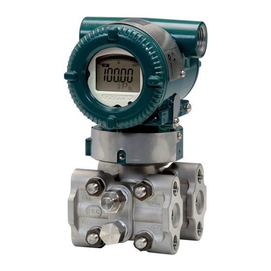
<3. Component Description> Component Description High Pressure Side Transmitter (Master) DRS cable connection port Conduit connection Slide switch assembly Zero-adjustment screw (Note 2) Integral indicator Transmitter (Note 1) Burnout direction switch BO H Mounting screw WR E Amplifier cover Write protection switch Burnout direction switch (BO) Hardware write protection switch (WR) Switch position... -
Page 27: Low Pressure Side Transmitter (Slave)
<3. Component Description> Low Pressure Side Transmitter (Slave) DRS cable connection port Transmitter CPU assembly Amplifier cover F0302.ai Figure 3.2 Component Names of the Low Pressure Side Transmitter (Slave) IM 01C25W05-01EN... -
Page 28: Installation
<4. Installation> Installation Precautions Mounting Before installing the transmitter, read the cautionary IMPORTANT notes in Section 2.4, “Selecting the Installation Location.” For additional information on the ambient As the pressure-detector diaphragm is thin and conditions allowed at the installation location, refer prone to damage, do not press on it or hit it to GS. - Page 29 <4. Installation> Vertical pipe mounting IMPORTANT 50 mm (2-inch) pipe Tighten the hexagonal nut part of the capsule assembly. See Figure 4.4. U-bolt (L) U-bolt (L) U-bolt (S) Pressure-detector section Mounting bracket U-bolt (S) Horizontal pipe mounting U-bolt (L) nut Mounting bracket F0404.ai 50 mm (2-inch) pipe...
- Page 30 IMPORTANT the mating gasket and clamp, They are also available from Tank • When measuring the liquid level of the tank, Yokogawa; if required, please order them separately. Refer to the minimum liquid level (zero point) must Table 4.2. Sleeve...
-
Page 31: Connecting The Drs Cable
<4. Installation> 4.3 Connecting the DRS Cable Mounting the C10FR Flushing Connection Ring Connect the DRS cable to the high pressure side transmitter (master) and low pressure side 4.4.1 Mounting to Pressure Detector transmitter (slave). Be careful of the termination Section when connecting. High pressure side Low pressure side The C10FR flushing connection ring is mounted... -
Page 32: Mounting To Process Flange
<4. Installation> 4.4.2 Mounting to Process Flange Tighten the bolts to completely close the gap between the ring and the pressure detector section. The mating flange, gasket, stud bolts and nuts are to be procured by the customer. Spiral gasket Mating flange Procured by customer Ring Diaphragm Gasket Pressure-detector section Procured by customer... -
Page 33: Affixing The Teflon Film
<4. Installation> 4.5 Affixing the Teflon Film Tank Spud Mounting Method The FEP Teflon option includes a Teflon film and A tank spud is used to joint a tank and an extended fluorinated oil. Before mounting the diaphragm seal diaphragm. to the process flange, affix the Teflon film as follows: It is imperative for sanitary use that the contact parts of the transmitter and the tank are securely IMPORTANT and tightly sealed in order to avoid the process fluid spouting and the decomposition by stagnant fluid. - Page 34 Finishing Welding Surface Make sure that all the welded parts are ground smooth and flat in a way that no dust is stuck to the surface. [Special Tools for Tank Spud Welding] Yokogawa provides special tools exclusively designed for the tank spud welding to make the installation easily and effectively. These tools can F0419.ai be ordered separately.
-
Page 35: Rotating Transmitter Section
<4. Installation> Rotating Transmitter Section Changing the Direction of Integral Indicator WARNING IMPORTANT For the flameproof type, as a general rule, do not rotate the transmitter while it is on. If you must do Always turn OFF power, release pressure and so, use a gas detector or the like to check that remove a transmitter to non-hazardous area there is no explosive gas. -
Page 36: Wiring
<5. Wiring> Wiring Wiring Precautions Connections of External Wiring to Terminal Box IMPORTANT 5.3.1 Power Supply Wiring Connection • Lay wiring as far as possible from electrical noise sources such as large capacity IMPORTANT transformers, motors, and power supplies. • Remove electrical connection dust cap Be sure to use a DC power supply with the before wiring. -
Page 37: Connecting The Hart Configuration Tool
<5. Wiring> Wiring 5.3.3 Connecting the HART Configuration Tool 5.4.1 Loop Configuration Connect the HART configuration tool to the SUPPLY + and – terminals (use hooks) of the high Since the DPharp uses a two-wire transmission pressure side transmitter (master). Polarity does not system, signal wiring is also used as power wiring. matter. A connection example is shown below. DC power is required for the transmitter loop. -
Page 38: Drs Cable Connection
<5. Wiring> 5.5 DRS Cable Connection (2) Flameproof Type Wire cables through a cable gland or using a Connect the DRS cable between the high pressure flameproof metal conduit. side transmitter (master) and low pressure side transmitter (slave). Wires can be run through a To low pressure side trasmitter cable gland or a wiring metal conduit. - Page 39 <5. Wiring> • Installing the cable gland High pressure side transmitter (master) 1. Disassemble the cable gland: loosen the running coupler to separate the backnut from the entry. 2. Remove the protection cap over the transmitter electrical connection and install the entry on the electrical connection.
- Page 40 <5. Wiring> 5. Position the running coupler so that it is Procedure along a straight line with the entry. (1) Disassemble the cable gland: loosen the all 6. Screw the running coupler until the seal parts touches the DRS cable. (2) Remove the protection cap on the DRS electrical connection and DRS connecting High pressure side transmitter (master)
-
Page 41: Wiring Through A Wiring Metal Conduit
<5. Wiring> 2. Insert the connector securely into the connection port. Rubber packing 3. Run the DRS cable through the wiring metal Gland conduit, and screw the conduit into the wiring port. 56.5±1 mm CAUTION Washer Packing box Do not pull on the cable or apply excessive F0522.ai mechanical shock to it. -
Page 42: Fixing The Drs Cable
<5. Wiring> 5.5.5 Fixing the DRS Cable High pressure side transmitter (master) WARNING If the DRS cable is 15 m or longer or if the Ground terminal flameproof packing adapter (cable gland) is not (Inside) tightened sufficiently, the weight of the cable Ground terminal itself may cause tension on the connector and (Outside) make the cable come off. Refer to the user’s manual of the flameproof packing adapter (cable gland), and fix the DRS cable in place so that Low pressure side transmitter (slave) tension is not applied to the connector. -
Page 43: Operation
<6. Operation> Operation Preparation for Starting ■ Checking with the integral indicator Operation • If the wiring system is faulty, the display stays blank. This section describes the operation procedure for • If the transmitter is faulty, an error code will measuring the liquid level of a closed tank shown appear on the display according to the nature of in Figure 6.1 using an EJXC40A digital remote the error. -
Page 44: Zero Point Adjustment
<6. Operation> Zero Point Adjustment b) Adjust output to the reference value obtained using other means. IMPORTANT In tank level measurement, if the actual level cannot be brought to zero for zero adjustment, then the Do not turn off the power to the transmitter output can be adjusted to correspond to the actual immediately after a zero adjustment. level obtained using another measuring instrument Powering off within 30 seconds after a zero such as a sight glass. -
Page 45: Starting Operation
<6. Operation> Shutting Down Operation Since the degree of zero adjustments varies with the screw turning speed, turn the screw slowly for To shut down operation, turn off the power. fine adjustment and quickly for coarse adjustment. NOTE High pressure side transmitter (master) Whenever shutting down the transmitter for a long period, detach the transmitter from the tank. Zero-adjustment screw Venting or Draining Transmitter Process-... -
Page 46: Draining Condensate From C10Fr Flushing Connection Ring
<6. Operation> 6.5.1 Draining Condensate from C10FR 6.5.2 Venting Gas from C10FR Flushing Flushing Connection Ring Connection Ring 1. Gradually open the drain screw to drain from 1. Gradually open the vent screw to vent gas from the flushing connection ring. the flushing connection ring. 2. When the flushing connection ring is completely 2. When the flushing connection ring is completely drained, close the drain screw. -
Page 47: Local Parameter Setting
<6. Operation> Local Parameter Setting 6.6.1 Local Parameter Setting (LPS) Overview WARNING Parameter configuration by the zero-adjustment screw and push button (integral indicator code E) The local push button on the integral indicator offers easy and quick setup for parameters of Tag must not be used in a hazardous area. When it is number, Unit, LRV, URV, Damping,Output mode necessary to use the push button, operate it in a (linear/square root/signal characterizer), Display out... - Page 48 <6. Operation> screw Process Zero adjustment Measurement Display push Activate LPS mode push 1. Tag Number Edit Tag number Save/Cancel the value 2. DP Unit Select DP unit Save/Cancel the value push 3. DP LRV Edit DP LRV Save/Cancel the value 4.
-
Page 49: Activating Local Parameter Setting
<6. Operation> 6.6.2 Activating Local Parameter Setting Press the push button on the integral indicator to activate the Local Parameter Setting mode. The transmitter will exit automatically from the Local Parameter Setting mode if no operation is carried out for 10 minutes. 6.6.3 Parameter Setting Review Current setting value for the below parameters are shown sequentially by each press of the push button. -
Page 50: Tag Number Configuration
<6. Operation> 6.6.4 Tag Number Configuration Tag Number is edited by turning the external adjustment screw. Up to 8 alphanumeric characters can be set. Save ?/ Cancel ? Blinking Blinking Set all other characters in the same way Change the first Character Go to the next Character screw push F0611.ai 6.6.5 Differential Pressure Unit Configuration Differential pressure unit for the below table can be changed as below. By turning the external adjustment screw, user can scroll between the various available pressure units. Save ?/ Cancel ? Blinking... -
Page 51: Damping Time Constant Configuration
<6. Operation> 6.6.7 Damping Time Constant Configuration The damping time constant for the differential prressure transmission part can be set. Damping time constant is rounded off to two decimal places. Save ?/ Cancel ? Blinking Blinking Blinking Set all other characters in the same way Change the first digit Go to the next Character screw Setting range: 0.00 to 100.00 (seconds) push F0613.ai IM 01C25W05-01EN... -
Page 52: Output Mode Configuration
6-10 <6. Operation> 6.6.8 Output Mode Configuration 8) Turn the external adjustment screw in the desired direction. The integral indicator displays Differential pressure Output Mode (“TRNS.FC” the output signal in %. (Note 2) shown on the integral indicator) can be selected 9) Adjust the output signal to 100% (5 V DC) by turning the external adjustment screw. -
Page 53: Abort Configuration
6-11 <6. Operation> 6.6.12 Abort Configuration 6.6.13 Local Parameter Setting Lock To disable parameter changes by the Local 6.6.12.1 Abort Configuration (Menu) Parameter Setting there are three different ways. Hold down the push button for over 2 seconds to Locked features exit the Local Parameter Setting mode. Communication Parameter • External Zero Ext SW =disable Adjustment •... -
Page 54: Hart Communication
<7. HART Communication> HART Communication In the explanation of HART communication, each of the digital remote sensor modules will be as follows. Master transmitter: Module 1 Slave transmitter: Module 2 By factory default, the master transmitter is configured for high pressure side measurement and the slave transmitter for low pressure side All on ↓... -
Page 55: Aligning Configuration Tool Dd And Device Revision
<7. HART Communication> (1) Checking the transmitter’s device revision NOTE ● To check using the integral indicator, (when the suffix code for integral indicator (D) is You can set the following parameter to display only the all-lit screen. specified), see subsection 7.1.1. ● Checking with the configuration tool 1) Connect the configuration tool to the • Recalling screen settings at power-on transmitter. Recall [Root menu] (See subsection 7.2.1.) 2) Select the root menu (see section 7.2.1). -
Page 56: Connecting Dpharp And Configuration Tool
DTM is used to set parameters, the menu (registered user website URL: https://voc. tree is as follows. yokogawa.co.jp/PMK/) To update the DTM, you need to perform the following operations using DTM setup. Root menu (DD) • Update the DTM catalog •... -
Page 57: Basic Setup
<7. HART Communication> 7.2.2 Basic Setup 7.2.2.2 Setting Process Variables The transmitter can handle five types of data (these IMPORTANT are called device variables): differential pressure (DP), module 1 side pressure (Pres 1), module After setting and sending data with the HART 2 side pressure (Pres 2), module 1 side capsule configuration tool, wait at least 30 seconds temperature (Temp 1), and module 2 side capsule before turning off the transmitter. -
Page 58: Unit
<7. HART Communication> 7.2.2.3 Unit 7.2.2.4 Measuring Range The unit is set at the factory before shipment if These range values are set as specified in the specified at the time of order. order before the instrument is shipped. Follow the To check or change the unit, follow the procedure procedure below to change the measuring range. below. -
Page 59: Output Mode
<7. HART Communication> If suffix code /CA is specified in the order, the NOTE differential pressure damping time constant may be set as specified at the time of order. It is possible to set LRV to a value greater than You can set the damping time constant to any value URV. In such a case, the 4 to 20 mA output within the 0.00 to 100.00 range. signal will be inverted. To change the damping time constant, follow the Setting conditions: LSL ≤ LRV ≤ USL procedure below. -
Page 60: Output Signal Low Cut
<7. HART Communication> 7.2.2.7 Output Signal Low Cut Because of hysteresis, the actual operation is as shown in the figure below. Low cut mode can be used to stabilize the output Example: When using linear output, zero low cut signal near the zero point. mode, and 20% low-cut value The low cut point can be set in a range from 0 to [For square root output]... -
Page 61: Detail Setup
<7. HART Communication> 7.2.3 Detail Setup (2) Setting the low limits (Pres 1 LRV, Pres 2 LRV) and high limits (Pres 1 URV, Pres 2 7.2.3.1 Pressure Signal Setup URV) of the pressure range On the digital remote sensor transmitter, high You can enter the low limits (Pres 1 LRV, Pres 2 pressure side pressure and low pressure side LRV) and high limits (Pres 1 URV, Pres 2 URV) of... -
Page 62: Impulse Line Connection Orientation Setup
<7. HART Communication> • Recalling bi-directional flow mode (Bi-dir mode) NOTE parameters Recall [Root menu] → Detailed setup → The damping time constant set here is only for parameters Signal condition → the pressure transmission part. Bi-dir mode Select On or Off. The damping time constant for the differential pressure(DP) is the sum of the damping Set the Bi-dir mode parameter to On. time constants for the differential pressure The factory default setting is Off. -
Page 63: Analog Signal Variable Range Setup
7-10 <7. HART Communication> 7.2.3.5 Analog Signal Variable Range 7.2.3.7 Integral Indicator Setup Setup The following 7 displays are available for integral The following table shows the factory default output indicators. range during normal operation, and the output is • PV percentage limited within this range. • Differential pressure •... - Page 64 7-11 <7. HART Communication> Table 7.2.2 Integral Indicator Display NOTE Integral Indicator Description and Display Related Parameters For user set scale PV value, the process value assigned to PV is applied to the user set scale. If PV percentage Displays percentage according to the (PV%) set PV range you change the PV, set the low limit (Engr LRV)
-
Page 65: Display Temperature Unit Setup
7-12 <7. HART Communication> 7.2.3.8 Display Temperature Unit Setup • Recalling and setting the differential pressure/ pressure decimal place parameters When the instrument is shipped, the temperature Recall [Root menu] → Detailed setup → units are set to deg C. parameters Display condition → Disp condition → To check the display temperature unit, follow the DP disp point Set the decimal place for differential procedure below. - Page 66 7-13 <7. HART Communication> (1) Zero Point Adjustment for Differential b) Adjust output to the reference value obtained Pressure using other means. In tank level measurement, if the actual level The transmitter supports several adjustment cannot be brought to zero for zero adjustment, methods. then the output can be adjusted to correspond Select the method best suited for the conditions of to the actual level obtained using another...
- Page 67 7-14 <7. HART Communication> c) Using the external zero-adjustment screw • Recalling and setting automatic adjustment Parameter Ext SW can be used to enable or parameters disable the zero point adjustment using the Recall [Root menu] → Maintenance → DP trim zero-adjustment screw on the transmitter. parameters → DP trim (method) To use the zero-adjustment screw, select Auto, Lower Set the low limit value you want to adjust.
-
Page 68: Analog Output Adjustment
7-15 <7. HART Communication> 6. Apply the high limit reference pressure of 30 7.2.3.10 Analog Output Adjustment kPa to the transmitter. We assume that the This function adjusts the analog output value. Two output display at this point is 30.15 kPa. adjustment methods, D/A output adjustment and 7. -
Page 69: External Switch Mode
7-16 <7. HART Communication> 7.2.3.11 External Switch Mode • For models with standard specifications or optional code /C3 This function is used to enable or inhibit zero point The burnout direction switch is set to high (H). If adjustment from the zero-adjustment screw on the an error occurs, the transmitter outputs a 110% or transmitter. -
Page 70: Signal Characterizer Setup
7-17 <7. HART Communication> 7.2.3.14 Signal Characterizer Setup 3. Apply the signal characterizer function After setting the coordinate values, setting This feature performs signal characterizer parameter “Xfer fnctn” to “Spcl curve” enables calculation for differential pressure percentage the signal characterizer and disables the values and outputs the result. This is used to obtain changing of data. -
Page 71: Alarm Setup
7-18 <7. HART Communication> • Setting screen of DTM (2) Setting the threshold Menu:[Device]→[Additional Functions]→[Signal Set the upper and lower threshold levels for Characterization] generating alarms. • Recalling threshold parameters Recall [Root menu] → Detailed setup → parameters Output condition → Process Alerts → DP Alert → Select differential pressure, and set the threshold. Pres 1 Alert → Select module 1 side pressure, and set the threshold. -
Page 72: Test Output, Simulation, And Squawk
7-19 <7. HART Communication> 7.2.3.16 Test Output, Simulation, and (2) Device variable simulation Squawk A value and status of your choice can be assigned to a device variable, and its output can be IMPORTANT confirmed. When the parameter is recalled, a message Test output,device variable simulation and status is displayed, so follow them. -
Page 73: Burst Mode
7-20 <7. HART Communication> (3) Squawk 7.2.3.17 Burst Mode This is used to determine with which transmitter If burst mode is enabled, the transmitter can communication is currently taking place. continuously send three of the data shown in Table There are two squawk modes; “once” mode 7.2.4 through HART communication. - Page 74 7-21 <7. HART Communication> Table 7.2.3 Burst mode target command parameters Burst Msg Trigger Burst Trigger Command parameter Burst Command Burst Trigger Units Mode Source Cmd1:PV Continuous — — Window Depends on PV assignment Rising Falling On-change % range/current Cmd2:% range/ Continuous — — (percent of range, Loop current) current Window % range...
- Page 75 7-22 <7. HART Communication> (2) Setting the burst mode Recall a burst mode parameter, Burst Message 1, 2, or 3, and set the parameter according to the following flow chart. Burst Command a. Burst Command Send to transmitter Cmd9, Cmd33 Burst Command? Cmd1, Cmd2, b. Burst Variables Burst Variable Code Cmd3, Cmd48 Send to transmitter Update Period c. Update period and Max Max Update Period Update Period by “Set Burst Period”...
- Page 76 7-23 <7. HART Communication> In the case of a burst command with send • Recalling a burst mode parameter conditions, the first assigned device variable [Root menu] → Detailed setup → Output Condition → becomes the trigger source. HART Output → Burst Condition → Burst Message 1, 2, or 3 → Burst Command 3. Set the send period. Set Update Period and Max Update Period. 1. Set the send data. Set the send data using burst command NOTE parameters.
- Page 77 7-24 <7. HART Communication> 4. Set send conditions. (3) Event notification Set the burst send conditions. Changes to device settings and changes to the Select a value for the Burst Msg Trigger Mode device status through self-diagnosis can be from the following table of parameters. detected as events, and alarm signals can be sent If Burst Msg Trigger Mode is set to Window, continuously.
- Page 78 7-25 <7. HART Communication> 2. Set the send time and minimum event retention (3-2) Acknowledging events (DTM only) time. When the host device acknowledges an event, Set the retry time for when events occur (Event event transmission stops. Notification Retry Time), the update time for To acknowledge events, follow the procedure when there are no events (Max Update Time), below.
-
Page 79: Multidrop Mode
7-26 <7. HART Communication> (3-3) Checking the event history (DTM only) 7.2.3.18 Multidrop Mode Event numbers can be used to view the past status Up to 63 devices that have been set to multidrop history of events that have occurred. mode can be connected to a single communication line. •... - Page 80 7-27 <7. HART Communication> (3) Enabling multidrop communication on the configuration tool side Refer to the configuration tool manual, and configure the receiver side polling settings. (4) Communication in multidrop mode 1. When the power is turned on, the HART configuration tool searches for devices set to multidrop mode. If the HART configuration tool is connected to devices, their polling addresses and tags are displayed. 2. Selecting the device of your choice enables communication with the selected device.
-
Page 81: Diagnostics
7-28 <7. HART Communication> Diagnostics When any abnormalities are detected, refer to Table 8.3 and take necessary measure. 7.3.1 Self-Diagnostics HART configuration tool performs diagnostics every communication transaction. If an inappropriate 7.3.1.1 Checking Using the HART operation is performed, an error message will be Configuration Tool displayed. -
Page 82: Ne107 Status Information
7-29 <7. HART Communication> (3) Data quality and limit status (5) Number of configuration changes This transmitter can handle differential pressure When you change parameters or perform (DP), module 1 side pressure (Pres 1), module calibration, the event is counted as a configuration 2 side pressure (Pres 2), module 1 side capsule change and saved as history. This value is never temperature (Temp 1), module 2 side capsule reset or written to when the power is turned off. -
Page 83: Advanced Diagnostics
Status group See table 8.3 0 to 5, 14 to impulse line and piping using EJX multi sensing (differential pressure, pressure, and temperature measurement) and Yokogawa’s original diagnostic By selecting [Device]→[Additional algorithm. The following two functions are available. Functions]→[Condensed Status] from the DTM ■ Impulse line blockage detection menu bar, four groups can be edited with using the setting screen in below. -
Page 84: Impulse Line Blockage Detection
7-31 <7. HART Communication> 7.3.2.2 Impulse Line Blockage Detection IMPORTANT Impulse Line Blockage Detection (ILBD) is • The basic element of impulse line blockage performed by statistically processing the measured detection is the monitoring of fluctuation. values of pressure fluctuation existing in the fluid. If sufficient fluctuation needed for The diagnostic results (blockage occurrences) determination cannot be obtained, blockage can be confirmed with the alarm indications on the detection does not work properly. - Page 85 7-32 <7. HART Communication> ■ Block Diagram EJX-DRS DP, Pres 1, Pres2 Engr Disp, PV % Temp1, Temp2, Amp Temp Sensor signals Process value 4-20 mA DC Sensor -------(6) calculation (Analog Output) Blockage alarm Diag Output Option Ratio fDP Ratio fP2 Ratio fP1 Fluctuation BlkF -------(1)
-
Page 86: Blockage Determination
7-33 <7. HART Communication> 7.3.2.2.1 Blockage Determination CAUTION ■ Limit parameter If you are using this for the first time, use the When a parameter based on pressure fluctuation default values. If not enough pressure fluctuation exceeds a preset threshold, a blockage is assumed can be detected in valve simulation tests or in to have occurred in the transmitter, and an alarm actual operation or if alarms occur frequently, is generated. -
Page 87: Combination Of The Reference Value And Blockage Detection Result
7-34 <7. HART Communication> ■ Determination of Pres 1 Side Blocking and ■ Determination of Pres 1 Side Blocking Pres 2 Side Blocking The BlkF value is prioritized in the determination In differential pressure measurement, it is possible of high pressure side blockage. However if the to detect which side, high pressure side or low BlkF blockage level is insufficient, Ratio fP1—the pressure side, of the impulse line has been blocked. square root of fP1 relative to Ref fP1 or SQRT (fP1/ To determine blockage on one side of the impulse Ref fP1)—is used in the determination of the high... - Page 88 7-35 <7. HART Communication> CAUTION • Ref fDP must be a value larger than the level specified in Table 7.3.2 of subsection 7.2.2.6. If sufficiently large Ref fDP cannot be obtained, blockage detection will not be possible. • The blockage detection function must be verified through blockage simulation test. A blockage simulation test is performed using a valve (see subsection 7.3.2.2.8). [Differential pressure measurement] Reference fluctuation...
-
Page 89: Operation Parameters
7-36 <7. HART Communication> 7.3.2.2.3 Operation Parameters ■ Diag Period Values such as fDP and BlkF are average values ■ Diag Mode based on several hundred pressure fluctuation The impulse line blockage detection function values obtained in a given time period. The Diag is performed by specifying three modes (Stop, Period parameter is used to specify the sampling Calculation, Reference) using the Diag Mode period. - Page 90 7-37 <7. HART Communication> Diag Supp Count (detection count: 3) Alarm occurrence Upper limit threshold (e.g., Lim fDPmax) Diag Period Time Diag Period Lower limit threshold (e.g., Lim fDPmin) Alarm occurrence Diag Supp Count (detection count: 3) Time F0716.ai Figure 7.3.4 Relationship between Diag Supp Count and alarms The detection count applies to all error alarms.
-
Page 91: Operating Procedure
7-38 <7. HART Communication> 7.3.2.2.4 Operating Procedure The basic ILBD operating procedure is provided below. 1) Initial setup 2) Condition confirmation 3) Startup 4) ILBD execution If alarms occur frequently or if the process conditions change during ILBD execution, change the alarm trigger conditions or reacquire the reference data. -
Page 92: Alert And Alarm Setup
7-39 <7. HART Communication> 7.3.2.2.5 Alert and Alarm Setup ■ ILBD over range Diagnostic results such as blockage detection and 1) Lim DPAvgmax flange temperature error (heat trace monitoring) The Lim DPAvgmax parameter indicates the can be confirmed with analog alerts and alarm upper limit of the detectable range of ILBD. The indications on the LCD. To display and output these value can be changed when ILBD is stopped results, configure the alarm and alert settings by (when the Diag Mode parameter is set to Stop). - Page 93 7-40 <7. HART Communication> ■ Analog alert setup ● Invalid Ref BlkF, Pres 1, Pres2, or DP This alarm indicates that the reference value ● Diag Out Option acquired under normal process conditions If impulse line blockage error or high- is invalid. If the Ref BlkF value is invalid as a temperature/low-temperature flange reference value, only the blockage detection temperature error occurs, the 4-20 mA analog that excludes the BlkF detection algorithm is...
-
Page 94: Condition Confirmation
7-41 <7. HART Communication> ■ Alarm LCD display ■ Pressure fluctuation value If ILBD detects an error, the detection result CAUTION information is indicated in alarm number AL.88 or AL.89 and on the LCD. • If the liquid’s pressure fluctuation is small, AL.88 indicates a condition in which errors cannot blockage detection does not work properly. be detected, and AL.89 indicates that an error has • The pressure fluctuation may be small in been detected. -
Page 95: Reference Value Acquisition
7-42 <7. HART Communication> 7.3.2.2.7 Reference Value Acquisition ■ Checking the reference values When the impulse line is blocked, the pressure The latest reference values are stored in the fluctuation value decreases. To detect this change, following parameters. a pressure fluctuation that can be used as a • Ref fDP reference for the damping rate is necessary. • Ref fP2 •... -
Page 96: Ilbd Execution
7-43 <7. HART Communication> ■ High pressure side blockage simulation test 7.3.2.2.9 ILBD Execution 1) Close the valve on the high pressure side. After checking the conditions and blockage 2) Check that the Pres 1 value is not changing detection capacity, start the actual blockage greatly. If it does, open the valve slightly. detection operation. - Page 97 7-44 <7. HART Communication> Move the threshold toward the white. In addition, increasing the detection count, a • It becomes increasingly likely to give a condition for generating alarms, with the Diag Supp false alarm due to the disturbance from Count parameter may also increase the blockage environment change.
-
Page 98: Resetting The Reference Value
7-45 <7. HART Communication> 7.3.2.2.11 Resetting the Reference Value If the flow rate is changed greatly or if the fluid is changed during plant operation, acquire the reference value again. If the flow rate changes by 25% or more relative to the flow rate that was present when the reference value was acquired, acquire the reference value again. When resetting the reference value, perform impulse line block purging as much as possible. 7.3.2.2.12 ILBD Parameter List Factory default Parameter name Description value Diag Error... - Page 99 7-46 <7. HART Communication> Factory default Parameter name Description value Ref fP2 Value of fP2 obtained under steady state operation used as a reference for blockage detection. Ref fP2 Status Status of Ref fP2 Ref fP1 Value of fP1 obtained under steady state operation used as a reference for blockage detection.
- Page 100 7-47 <7. HART Communication> Factory default Parameter name Description value CRatio fDP Status Status of CRatio fDP NRatio fDP When Non-compensation is selected in Diag DP Comp, NRatio fDP is used as the monitoring value. NRatio fDP = Sqrt (fDP / Ref fDP) NRatio fDP Status Status of NRatio fDP Diag DPComp Compensation Flow rate compensation flag.
-
Page 101: Heat Trace Monitoring
7-48 <7. HART Communication> 7.3.2.3 Heat Trace Monitoring [Formula] Flg temp (FT) = CT + Cf × (CT – AT) The heat trace monitoring function calculates the flange temperature based on the capsule temperature and amplifier temperature measured CAUTION with the sensors on the transmitter and generates alarms when the preset temperature threshold is The flange temperature is calculated with the exceeded. -
Page 102: Flg Temp Coef Setting
7-49 <7. HART Communication> 7.3.2.3.1 Flg temp coef Setting 7.3.2.3.2 Alarm Generation The value calculated according to the following Alerts and alarms can be generated when the procedure is set to Flg temp coef. flange temperature goes outside the preset • To improve the calculation accuracy of measuring range. -
Page 103: Heat Trace Monitoring Parameter List
7-50 <7. HART Communication> 7.3.2.3.3 Heat Trace Monitoring Parameter List Factory Parameter name Description default value Diag Error 0x0000 The results detected by ILBD or heat trace monitoring are stored in this parameter. Also the condition abnormality in the diagnostic process is stored as an error. -
Page 104: Maintenance
<8. Maintenance> Maintenance Overview 8.2 Calibration Instrument Selection WARNING Table 8.1 lists the instruments that can be used to calibrate a transmitter. When selecting an • Since the accumulated process fluid instrument, consider the required accuracy may be toxic or otherwise harmful, take level. Exercise care when handling these appropriate care to avoid contact with the instruments to ensure they maintain the body or inhalation of vapors when draining... - Page 105 <8. Maintenance> Table 8.1 Instruments Required for Calibration Name Yokogawa-recommended Instrument Remarks Power supply Model SDBT or SDBS distributor 4 to 20 mA DC signal Load resistor Model 2792 standard resistor [250 Ω ±0.005%, 3 W] Load adjustment resistor [100 Ω ±1%, 1 W] Voltmeter Model 2501 A digital multimeter Accuracy (10V DC range): ±(0.002% of rdg + 1 dgt)
-
Page 106: Calibration
<8. Maintenance> 8.3 Calibration IMPORTANT Use the procedure below to check instrument 1. To adjust the transmitter for highest operation and accuracy during periodic accuracy, make adjustments with the maintenance or troubleshooting. power supply voltage and load resistance 1. Connect the instruments as shown in Figure 8.1 including leadwire resistances set close to and warm up the instruments for at least five the conditions under which the transmitter... -
Page 107: Disassembly And Reassembly
If such modification is absolutely required, Tighten the shrouding bolt to a torque of 0.7 contact Yokogawa. N·m {7 kgf·cm}. ■ Removing the Integral Indicator 1. Remove the cover. 2. While supporting the integral indicator with one hand, loosen its two mounting screws. -
Page 108: Replacing The Cpu Board Assembly
<8. Maintenance> 4. Disconnect the DRS output cable (cable with High pressure side transmitter (master) white connector at the end). DRS cable 5. Use a socket driver (width across flats, 5.5mm) connection port Output terminal cable to loosen the two bosses. 6. Carefully pull the CPU assembly straight forward to remove it. Press forward 7. Disconnect the flat cable (cable with white Slide switch connector at the end) that connects the CPU... -
Page 109: Cleaning And Replacing The Capsule Assembly
■ Assembling the Capsule Assembly you want to replace the capsule assembly with another with a different measurement range, 1. Attach the transmitter section to the pressure- contact Yokogawa. detector section. If you want to replace the capsule assembly with 2. F asten the stopper’s setscrews. Fasten the two another with the same measuring range, only do shrouding bolts. -
Page 110: Troubleshooting
• Output value is inconsistent with value not identify all. If you have difficulty isolating or inferred for process variable. correcting a problem, contact Yokogawa service personnel. Connect HART configuration tool and check self-diagnostics. 8.5.1 Basic Troubleshooting First determine whether the process variable... - Page 111 Use the transmitter within the measurement range shown on the data plate. Is output adjusted correctly? Adjust the zero point. Is zero point adjusted correctly? Contact Yokogawa service personnel. Adjust the zero point. F0808.ai Contact Yokogawa service personnel. F0807.ai IM 01C25W05-01EN...
-
Page 112: Alarms And Countermeasures
<8. Maintenance> 8.5.3 Alarms and Countermeasures Table 8.3 Errors Message Summary NE107 Display on Diagnostic Output Operation Status Indicator (Default Configuration Cause Countermeasure List during Error Group Value) Tool Group AL. 01 Pres 1 Sensor Module-1: Pressure The output is shifted Contact the nearest CAP1.ER Failure (AL-01) sensor failed. - Page 113 8-10 <8. Maintenance> NE107 Display on Diagnostic Output Operation Status Indicator (Default Configuration Cause Countermeasure List during Error Group Value) Tool Group AL.10 DP outside Limit Differential pressure Continues to output Check the input. DIFF.P (AL-10) exceeds limit. (AL-10) the current value. Contact the nearest If the relevant signal sales office or service...
- Page 114 8-11 <8. Maintenance> NE107 Display on Diagnostic Output Operation Status Indicator (Default Configuration Cause Countermeasure List during Error Group Value) Tool Group AL.30 DP over Range. Differential pressure Continues to output Check input and range DP.RNG (AL-30) exceeds specified the current value. setting, and change range.
- Page 115 8-12 <8. Maintenance> NE107 Display on Diagnostic Output Operation Status Indicator (Default Configuration Cause Countermeasure List during Error Group Value) Tool Group AL.50 Illegal DP LRV Specified value is Holds output Check setting and DP. LRV (AL-50) outside of setting range. immediately before change them as (AL-50) error occurred.
- Page 116 8-13 <8. Maintenance> NE107 Display on Diagnostic Output Operation Status Indicator (Default Configuration Cause Countermeasure List during Error Group Value) Tool Group AL.87 Flg Temp High Module-1: Flange Follows the Diag Out 1) Check heater FLG. HI Alarm (AL-87) temperature exceeds Option settings.
- Page 117 8-14 <8. Maintenance> NE107 Display on Diagnostic Output Operation Status Indicator (Default Configuration Cause Countermeasure List during Error Group Value) Tool Group AL.91 DP Simulate Mode Under simulation mode Outputs the Check the simulation DP. SIM (AL-91) for differential pressure. Simulate-Value mode. (AL-91) value. AL.91 Pres 1 Simulate Under simulation mode...
- Page 118 8-15 <8. Maintenance> Table 8.4 HART Configuration Error Message Error message Probable cause Countermeasure Invalid selection — Change the setting. Value was too high Set value is too high. Value was too low Set value is too low. Too few data bytes received — — In write protect mode Operation is set in the Write Protect mode.
- Page 119 8-16 <8. Maintenance> Table 8.6 Extended Device Status and Diagnostic Status 0, 1 Extended device status NE107 Description (Ext dev Status) (Default Value) Maintenance Required (0x01) Field device requires maintenance. Device Variable Alert (0x02) Any device variable is in an alarm or warning state. Critical Power Failure (0x04) Not used Failure (0x08) One or more device variables are invalid due to a malfunction in the...
- Page 120 8-17 <8. Maintenance> Table 8.8 Relationship between Alarm and Value/Status Value and Status (Data Quality, Limit Status) Integral Display on Extended NE107 Device Module 1 Module 2 Indicator Configuration Device (Default Differential Current Status Capsule Capsule Display Tool Status Value) pressure Range Output Pressure Pressure Temperature Temperature AL.
- Page 121 8-18 <8. Maintenance> Value and Status (Data Quality, Limit Status) Integral Display on Extended NE107 Device Module 1 Module 2 Indicator Configuration Device (Default Differential Current Status Capsule Capsule Display Tool Status Value) pressure Range Output Pressure Pressure Temperature Temperature AL.03 Pres 2 Sensor Device...
- Page 122 8-19 <8. Maintenance> Value and Status (Data Quality, Limit Status) Integral Display on Extended NE107 Device Module 1 Module 2 Indicator Configuration Device (Default Differential Current Status Capsule Capsule Display Tool Status Value) pressure Range Output Pressure Pressure Temperature Temperature AL.10 DP outside [In the case of...
- Page 123 8-20 <8. Maintenance> Value and Status (Data Quality, Limit Status) Integral Display on Extended NE107 Device Module 1 Module 2 Indicator Configuration Device (Default Differential Current Status Capsule Capsule Display Tool Status Value) pressure Range Output Pressure Pressure Temperature Temperature AL.35 DP High Alarm —...
- Page 124 8-21 <8. Maintenance> Value and Status (Data Quality, Limit Status) Integral Display on Extended NE107 Device Module 1 Module 2 Indicator Configuration Device (Default Differential Current Status Capsule Capsule Display Tool Status Value) pressure Range Output Pressure Pressure Temperature Temperature AL.50 Illegal DP LRV —...
- Page 125 8-22 <8. Maintenance> Value and Status (Data Quality, Limit Status) Integral Display on Extended NE107 Device Module 1 Module 2 Indicator Configuration Device (Default Differential Current Status Capsule Capsule Display Tool Status Value) pressure Range Output Pressure Pressure Temperature Temperature AL.57 Pres 2 Zero —...
- Page 126 8-23 <8. Maintenance> Value and Status (Data Quality, Limit Status) Integral Display on Extended NE107 Device Module 1 Module 2 Indicator Configuration Device (Default Differential Current Status Capsule Capsule Display Tool Status Value) pressure Range Output Pressure Pressure Temperature Temperature AL.87 Flg Temp High —...
- Page 127 8-24 <8. Maintenance> Value and Status (Data Quality, Limit Status) Integral Display on Extended NE107 Device Module 1 Module 2 Indicator Configuration Device (Default Differential Current Status Capsule Capsule Display Tool Status Value) pressure Range Output Pressure Pressure Temperature Temperature AL.91 DP Simulate [In the case of...
-
Page 128: Parameter Summary
<9. Parameter Summary> Parameter Summary Table 9.1 Parameter Summary Factory Default Function Label Item Description Value Analog output AO Alrm typ Output during hardware Indicates the output level during hardware Depends on the failure errors (including CPU errors) (Hi, Lo) hardware switch AO lower limit Lower limit of analog Sets the lower limit of output current. - Page 129 <9. Parameter Summary> Factory Default Function Label Item Description Value Event Event Notification Event Notification Switches to or out of event monitoring mode. notification Control This can be set to On only when burst mode is set to Wired HART Enabled. Device status Event masking Sets the device status to detect as events.
- Page 130 Message Message Free text. Up to 32 alphanumerics. Country Country code Country code Dev id Device ID Device ID Distributor Distributor Distributor YOKOGAWA Drain vent matl Drain/Vent plug material Drain/Vent plug material Extra No. Customization number Customization number Fill fluid Fill fluid material Fill fluid material Final asmbly num Final assembly number Final assembly number...
- Page 131 <9. Parameter Summary> Factory Default Function Label Item Description Value Display setup Bar indicator Bar graph display setting Specifies bar indicator (bar graph) on or off. (On, Off) Power on info Screen at power-on Sets how to display the screen at power-on. (On, Off) Disp Out 1 Integral indicator display Specifies the contents to display on the LCD.
- Page 132 <9. Parameter Summary> Factory Default Function Label Item Description Value Loop test Loop test Test output Outputs a 4-20 mA test signal. Set in unit of mA. (3.8 to 21.6 mA) Test Auto Release Auto test release time Sets the auto release time for loop test, 10 min Time device variable simulation and status...
- Page 133 <9. Parameter Summary> Factory Default Function Label Item Description Value Device DP Limit Status Device variable limit Indicates the limit status of the differential variable status status pressure. (Table 8.7) DP Data Quality Device variable data Indicates the quality status of the differential quality pressure. (Table 8.7) Pres 1 Limit Status Device variable limit Indicates the limit status of the module 1 side status pressure.
- Page 134 <9. Parameter Summary> Factory Default Function Label Item Description Value Sensor Clear DP trim Differential pressure Clears the differential pressure adjustment adjustment level clear level. Cler Pres 1 trim Module 1 side pressure Clears the module 1 side pressure adjustment level clear adjustment level. Cler Pres 2 trim Module 2 side pressure Clears the module 2 side pressure adjustment level clear...
- Page 135 <9. Parameter Summary> Factory Default Function Label Item Description Value Signal Num of points Number of points Set the number of points for signal characterizer characterizer.(0 to 30) Tank memo Description about the Stores description about the tank settings. tank settings Up to 32 alphanumeric characters X1 to X30 X coordinate...
- Page 136 <9. Parameter Summary> Factory Default Function Label Item Description Value Status Device status Field device status Indicates the status. Diagnostic status 0 Diagnostic status Indicates device diagnostic status Diagnostic status 1 Diagnostic status Indicates device diagnostic status Status group 0 Hardware status Indicates module 1 side hardware failure information...
- Page 137 9-10 <9. Parameter Summary> Factory Default Function Label Item Description Value Temperature T.Z. Cmp mode 1 Module 1 side Selects the module 1 side temperature zero compensation temperature zero compensation mode (On, Off) compensation mode T.Z. Cmp mode 2 Module 2 side Selects the module 2 side temperature zero temperature zero compensation mode (On, Off) compensation mode...
- Page 138 9-11 <9. Parameter Summary> Factory Default Function Label Item Description Value Process Change PV Assgn PV assignment Specifies the variable to assign to PV variables (primary variable). (DP, Pres 1, Pres 2) PV is PV assignment Indicates the variable currently assigned to Change SV Assgn SV assignment Specifies the variable to assign to SV(secondary variable).(DP, Pres 1, Pres 2, Temp 1, Temp 2)
- Page 139 9-12 <9. Parameter Summary> Factory Default Function Label Item Description Value Advanced Diag Applicable Detectable diagnostic Indicates the available blockage detection R, G diagnostic functions after acquiring the reference (ILBD) values. Diag DPComp Ratio fDP compensation Enables or disables Ratio fDP Compensation W, G selection...
- Page 140 9-13 <9. Parameter Summary> Factory Default Function Label Item Description Value Advanced Ref fP1 Status Status of Ref fP1 R, G diagnostic Ref BlkF BlkF reference value W, G (ILBD) Ref BlkF Status Status of Ref BlkF R, G Ref DPAvg DPAvg reference value W, G Ref DPAvg Status...
-
Page 141: General Specifications
10-1 <10. General Specifications> 10. General Specifications Please refer to the following General Specifications list for the specifications, model, suffix and option codes, and external dimensions of each product. For the specifications specific to the Digital Remote Sensor, refer to the General Specification GS 01C25W05- 01EN, and GS 01C25W01-01EN if flange mounted type is specified. For those specifications which are common with the original transmitters, refer to the General Specifications of each transmitter(EJX530A or EJX630A.) The General Specifications can be downloaded from the website of Yokogawa. Website address: https://www.yokogawa.com/solutions/products-platforms/field-instruments/ ■ General Specifications List Model Document Title Document No. EJX110A Differential Pressure Transmitter GS 01C25B01-01EN EJX120A Differential Pressure Transmitter GS 01C25B03-01EN EJX130A Differential Pressure Transmiter GS 01C25B04-01EN... -
Page 142: Appendix 1. Safety Instrumented Systems Installation
The transmitter will report an internal failure within management system. Failures that are detected should be reported to Yokogawa. 10 seconds of the fault occurrence. The personnel performing the proof test of the A1.2.3 Setup... -
Page 143: A1.2.6 Repair And Replacement
In the unlikely event that the transmitter has a The transmitter is certified up to SIL2 for use failure, the failures that are detected should be in a simplex (1oo1) configuration, depending reported to Yokogawa. on the PFDavg calculation of the entire Safety When replacing the transmitter, the procedure in the Instrumented Function. -
Page 144: A1.2.10 Lifetime Limits
A1-3 <Appendix1. Safety Instrumented Systems Installation> A1.2.10 Lifetime Limits Validation The demonstration that the safety-related The expected lifetime of the transmitter is 50 system(s) or the combination of safety-related years. The reliability data listed the FMEDA report system(s) and external risk reduction facilities is only valid for this period. -
Page 145: Appendix 2. Ilbd Check List
A2-1 <Appendix 2. ILBD Check List> Appendix 2. ILBD Check List Fill out the below checklist according to the operation flow of the ILBD in order to keep the important information for the blockage detection. Checklist (1/5) Items Parameters Result Example 4-20 mA Analog Signal Setting Off: Diag Out Option Burnout: • Select the output mode when an alarm is Fall back: ... - Page 146 A2-2 <Appendix 2. ILBD Check List> Checklist (2/5) Items Parameters Result Example Alarm status Diag Error A Blocking • Check the alarm status shown in Diag Error. Large Fluct Pres 2 • Check that the alarm status of “ILBD over ...
- Page 147 A2-3 <Appendix 2. ILBD Check List> Checklist (3/5) Go to the following step according to the result of "Invalid Ref xx" shown in the Diag Error of 8th check item. Diag Error Check item Invalid Ref Pres 1 Invalid Ref Pres 2 Invalid Ref DP →...
- Page 148 A2-4 <Appendix 2. ILBD Check List> Checklist (4/5) Items Parameters Result Example 9-a-2 L Side Blocking • Close the low-pressure side valve completely. • Record the values of fDP, fP2, fP1, and BlkF fDP* 6.48562E-08 after the certain time, fP2* 2.23277E-10 (Diag Period X Diag Supp Count), passed.
- Page 149 A2-5 <Appendix 2. ILBD Check List> Checklist (5/5) Items Parameters Result Example Simulation of Blockage detection operation • Close completely the valve for the side where the alarm of Invalid Reference Value is not generated. For the case that the high-pressure side value is closed;...
-
Page 150: Revision Information
Rev-1 Revision Information Title : Digital Remote Sensor Manual No. : IM 01C25W05-01EN Edition Date Page Revised Item June 2016 — New publication Dec. 2016 — Add hygienic type direct mounted seal. Add /FS14, /FU14, /KS24, /KU24, /SS24 and /SU24. 1. Add WARNING for the digital remote sensor’s model structure. Modify NOTE. 2.1 Modify figure 2.2 Add 2.9. 4.2 Add information for hygienic seals.
Need help?
Do you have a question about the DPharp EJXC40A and is the answer not in the manual?
Questions and answers