
Subscribe to Our Youtube Channel
Related Manuals for YOKOGAWA DpharpEJX vigilantplant EJX110


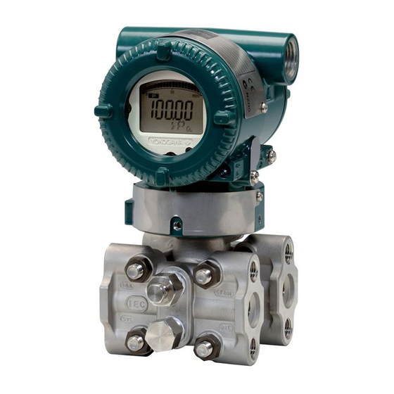
Summary of Contents for YOKOGAWA DpharpEJX vigilantplant EJX110
- Page 1 User’s Manual EJX110A, EJX130A, EJX310A, EJX430A and EJX440A Differential Pressure and Pressure Transmitters IM 01C25B01-01E IM 01C25B01-01E 5th Edition Y okogawa Electric Corporation...
-
Page 2: Table Of Contents
Selecting the Wiring Materials ............6-1 Connections of External Wiring to Terminal Box ........ 6-1 6.3.1 Power Supply Wiring Connection ..........6-1 FD No. IM 01C25B01-01E IM 01C25B01-01E 5th Edition: July 2006(YK) All Rights Reserved, Copyright © 2004, Yokogawa Electric Corporation... - Page 3 CONTENTS 6.3.2 External Indicator Connection ............6-1 6.3.3 Communicator Connection ............6-1 6.3.4 Check Meter Connection .............. 6-2 6.3.5 Status Output Connection ............6-2 Wiring ....................6-2 6.4.1 Loop Configuration ............... 6-2 General-use Type and Flameproof Type ........6-2 Intrinsically Safe Type ..............6-2 6.4.2 Wiring Installation .................
-
Page 4: Introduction
• All rights reserved. No part of this manual may be before you operate the instrument. reproduced in any form without Yokogawa’s written permission. • Yokogawa makes no warranty of any kind with NOTE regard to this manual, including, but not limited to, This manual describes the hardware configura- implied warranty of merchantability and fitness for a tions of EJX series transmitters. -
Page 5: Safe Use Of This Product
Indicates a potentially hazardous situation which, protection provided by this instrument may be im- if not avoided, could result in death or serious paired. In this case, Yokogawa cannot guarantee that injury. the instrument can be safely operated. Please pay... -
Page 6: Warranty
Yokogawa. (f) Modification • The purchaser shall bear the responsibility for repair • Yokogawa will not be liable for malfunctions or costs, even during the warranty period, if the damage resulting from any modification made to this malfunction is due to: instrument by the customer. -
Page 7: Atex Documentation
Se si desidera ricevere i manuali operativi di prodotti Ex in lingua locale, mettersi in Alle Betriebsanleitungen für ATEX Ex bezogene contatto con l’ufficio Yokogawa più vicino o con un Produkte stehen in den Sprachen Englisch, Deutsch rappresentante. -
Page 8: Handling Cautions
2. HANDLING CAUTIONS HANDLING CAUTIONS This chapter provides important information on how to 2.1 Model and Specifications handle the transmitter. Read this carefully before using Check the transmitter. EJX Series transmitters are thoroughly tested at the The model name and specifications are written on the factory before shipment. -
Page 9: Selecting The Installation Location
2. HANDLING CAUTIONS (b) Make sure that there are no leaks in the impulse 2.4 Selecting the Installation piping. Location (c) Never apply a pressure higher than the specified maximum working pressure. The transmitter is designed to withstand severe environmental conditions. However, to ensure that it 2.6 Waterproofing of Cable will provide years of stable and accurate performance, take the following precautions when selecting the... -
Page 10: Installation Of An Explosion-Protected Instrument
• Ambient temperature: –60 to 60 C intrinsically safe or explosionproof construction may be compromised and the instrument may be hazardous to operate. Please contact Yokogawa before making any repair or modification to an instrument. IM 01C25B01-01E... - Page 11 [Groups A, B, C, D, E, F and G] by other than authorized representative of Vmax = 30 V Ci = 6 nF Yokogawa Electric Corporation is prohibited and Imax = 200 mA Li = 0 H will void Factory Mutual Intrinsically safe and Pmax = 1 W Nonincendive Approval.
-
Page 12: Csa Certification
• Ambient Temperature :–50 to 60 C by other than authorized representative of • Max. Process Temp.: 120 C Yokogawa Electric Corporation is prohibited and • Enclosure: IP66 and IP67 will void Factory Mutual Explosionproof Approval. Note 2. Entity Parameters •... - Page 13 2. HANDLING CAUTIONS Note 2. Wiring [Intrinsically Safe] Hazardous Location Nonhazardous Location [For CSA C22.2] Group IIC, Zone 0 • All wiring shall comply with Canadian Electrical Class I, II, III, Division 1, Code Part I and Local Electrical Codes. Groups A, B, C, D, E, F, G General •...
-
Page 14: Cenelec Atex (Kema) Certification
Explosionproof) for use in hazardous locations. by other than authorized representative of Note 1. For the installation of this transmitter, Yokogawa Electric Corporation is prohibited and once a particular type of protection is will void KEMA Intrinsically safe Certification. selected, any other type of protection Note 5. - Page 15 • The instrument modification or parts replacement Note 4. Operation by other than authorized representative of • Keep the “WARNING” label attached to the Yokogawa Electric Corporation is prohibited and transmitter. will void Type of Protection “n”. WARNING: AFTER DE-ENERGIZING, DELAY 5 MINUTES BEFORE OPENING.
- Page 16 *2: “180-8750” is a zip code which represents the following address. WARNING 2-9-32 Nakacho, Musashino-shi, Tokyo Japan The instrument modification or parts replacement by other than an authorized Representative of Yokogawa Electric Corporation is prohibited and will void the certification. IM 01C25B01-01E...
-
Page 17: Iecex Certification
/SU2 can be selected the type of by other than authorized representative of protection (IECEx Intrinsically Safe/type n or Yokogawa Electric Corporation and will void flameproof) for use in hazardous locations. IECEx Intrinsically safe and type n certification. -
Page 18: Emc Conformity Standards
• The instrument modification or parts replacement EJX310A 0.01 Article 3, Paragraph 3 M, A, B by other than authorized representative of (SEP) Yokogawa Electric Corporation is prohibited and EJX430A 0.01 Article 3, Paragraph 3 H, A, B will void IECEx Certification. (SEP) -
Page 19: Low Voltage Directive
2. HANDLING CAUTIONS 2.12 Low Voltage Directive Applicable standard : EN61010-1 (1) Pollution Degree 2 "Pollution degree" describes the degree to which a soild, liquid, or gas which deteriorates dielectric strength or surface resistivity is adhering. " 2 " applies to normal indoor atmosphere. Normally, only non-conductive pollution occurs. -
Page 20: Component Names
3. COMPONENT NAMES COMPONENT NAMES Vertical impulse piping type Pressure-detector section Terminal box cover Cover flange Horizontal impulse piping type External indicator (Note 1) conduit connection Conduit connection Zero- adjustment screw (Note 2) Slide switch Integral (Note 1) indicator Mounting screw Vent plug CPU assembly Drain plug... -
Page 21: Installation
4 . INSTALLATION INSTALLATION 4.1 Precautions Vertical pipe mounting Before installing the transmitter, read the cautionary notes in section 2.4, “Selecting the Installation Loca- tion.” For additional information on the ambient conditions allowed at the installation location, refer to Transmitter subsection 9.1 “Standard Specifications.”... -
Page 22: Changing The Process Connection
4 . INSTALLATION 4.3 Changing the Process Con- Vertical pipe mounting (Process connector downside) nection Transmitter The transmitter is shipped with the process connection mounting bolt specified at the time of ordering. To change the process connection,the drain (vent) plug must be repositioned. Mounting bracket To reposition a drain (vent) plug, use a wrench to slowly and gently unscrew it. -
Page 23: Swapping The High/Low-Pressure Side Connection
4 . INSTALLATION 4.4 Swapping the High/Low- 4.4.2 Using the Communicator pressure Side Connection This method is applicable only to the Model EJX110A and EJX130A. With a communicator, you can change which process IMPORTANT connection is used as the high-pressure side without This section is applicable only for EJX110A and mechanically rotating the pressure-detector section 180 EJX130A differential transmitters, and not... -
Page 24: Rotating Transmitter Section
4 . INSTALLATION 4.5 Rotating Transmitter Section 4.6 Changing the Direction of Integral Indicator The transmitter section can be rotated approximately 360 (180 to either direction or 360 to one direction from the original position at shipment, depending on IMPORTANT the configuration of the instrument.) It can be fixed at any angle within above range. -
Page 25: Installing Impulse Piping
5. INSTALLING IMPULSE PIPING INSTALLING IMPULSE PIPING 5.1 Impulse Piping Installation (2) Changing the Process Connector Piping Connections (Figure 4.1) (for differential Precautions pressure transmitters) The impulse piping that connects the process outputs to The impulse piping connection distances can be the transmitter must convey the process pressure changed between 51 mm, 54 mm and 57 mm by accurately. -
Page 26: Routing The Impulse Piping
5. INSTALLING IMPULSE PIPING 3) Install the pipe assemblies between the 3-valve NOTE manifold and the process connectors and lightly tighten the ball head lock nuts. (The ball-shaped ends of the pipes must be handled carefully, since After completing the connection of the transmit- they will not seal properly if the ball surface is ter and 3-valve manifold, be sure to CLOSE the scratched or otherwise damaged.) - Page 27 5. INSTALLING IMPULSE PIPING (2) Position of Process Pressure Taps and (6) Preventing Wind Speed Effects in Very Transmitter Low Differential Pressure Measurement (for differential pressure transmitters) If condensate (or gas) accumulates in the impulse piping, it should be removed periodically by opening the drain (or vent) plugs.
-
Page 28: Impulse Piping Connection Examples
5. INSTALLING IMPULSE PIPING 5.2 Impulse Piping Connection Liguid Steam Examples Orifice Condensate pot Figure 5.5 and 5.6 show examples of typical impulse valve piping connections. Before connecting the transmitter to the process, study the transmitter installation Union location, the process piping layout, and the characteris- or flange tics of the process fluid (corrosiveness, toxicity, flammability, etc.), in order to make appropriate... -
Page 29: Wiring
6. WIRING WIRING 6.1 Wiring Precautions 6.3 Connections of External Wiring to Terminal Box 6.3.1 Power Supply Wiring Connection IMPORTANT Connect the power supply wiring to the SUPPLY + • Lay wiring as far as possible from electrical and – terminals. When /AL is specified, also refer to noise sources such as large capacity transform- subsection 6.3.5. -
Page 30: Check Meter Connection
6. WIRING (1) General-use Type and Flameproof Type 6.3.4 Check Meter Connection Available only when /AL is not specified. Hazardous Location Nonhazardous Location Connect the check meter to the CHECK + and – Transmitter terminal box terminals. (Use hooks.) Distributor (Power supply unit) •... -
Page 31: Flameproof Type
6. WIRING 6.5 Grounding (2) Flameproof Type Wire cables through a flameproof packing adapter, or Grounding is always required for the proper operation use a flameproof metal conduit. of transmitters. Follow the domestic electrical require- Wiring cable through flameproof packing adapter. ments as regulated in each country. -
Page 32: Operation
7. OPERATION OPERATION 7.1 Preparation for Starting Venting Gas from the Transmitter Pressure- detector Section Operation • Since the piping in the example of figure 7.1 is constructed to be self-venting, no venting operation is This section describes the operation procedure for the required. -
Page 33: Zero Point Adjustment
7. OPERATION NOTE Vent plug (Fill plug) If any of the above errors are indicated on the display of the integral indicator or the communi- Tap valve cator, refer to subsection 8.5.3 for the corrective action. Stop valve Verify and Change Transmitter Parameter Setting and Values The parameters related to the following items are set at factory as specified in order. -
Page 34: Adjusting Zero Point For Differential Pressure Transmitters
7. OPERATION (2) When you cannot obtain the Low Range 7.2.1 Adjusting Zero Point for Differential Value from the actual measured value of 0%; Pressure Transmitters Adjust the transmitter output to the actual measured Before adjusting zero point, make sure that the equaliz- value obtained by a digital manometer or a glass ing valve is open. -
Page 35: Shutting Down The Transmitter
7. OPERATION 7.5.1 Draining Condensate • Tighten the zero-adjustment cover mounting screw to secure the cover. 1) Gradually open the drain screw or drain plug and drain the transmitter pressure-detector section. (See figure 7.5.) 7.4 Shutting Down the Transmitter 2) When all accumulated liquid is completely re- moved, close the drain screw or drain plug. -
Page 36: Setting The Range Using The Range-Setting Switch
7. OPERATION Note 1: Wait until the pressure inside the pressure-detector section 7.6 Setting the Range Using the has stabilized before proceeding to the next step. Range-setting Switch Note 2: If the pressure applied to the transmitter exceeds the previous LRV (or URV), the integral indicator may display error number “AL.30”... -
Page 37: Maintenance
8. MAINTENANCE MAINTENANCE 8.1 Overview 8.2 Calibration Instruments Se- lection WARNING Table 8.1 lists the instruments that can be used to calibrate a transmitter. When selecting an instrument, Since the accumulated process fluid may be consider the required accuracy level. Exercise care toxic or otherwise harmful, take appropriate care when handling these instruments to ensure they to avoid contact with the body or inhalation of... - Page 38 0.1% or higher level, there may be difficulties in calibration to this level in the field. For calibration to the 0.1% level, contact Yokogawa representatives from which the instrument was purchased or the nearest Yokogawa office.
-
Page 39: Disassembly And Reassembly
Phillips screwdriver JIS B4633, No. 2 indicator to a transmitter. If such modification is Slotted screwdriver absolutely required, contact Yokogawa. Allen wrenches JIS B4648 One each, nominal 3, 4 and 2.5 mm Allen wrenches... -
Page 40: Replacing The Cpu Board Assembly
If the capsule. you wish to replace the capsule assembly with one of a different measurement range, contact Yokogawa. NOTE The user is permitted, however, to replace a Be careful not to apply excessive force to the capsule assembly with another of the same CPU assembly when removing it. -
Page 41: Replacing The Process Connector Gaskets
8. MAINTENANCE Removing the Capsule Assembly 7) After completing reassembly, adjust the zero point and recheck the parameters. IMPORTANT Transmitter section Exercise care as follows when cleaning the capsule assembly. • Handle the capsule assembly with care, and be especially careful not to damage or distort the diaphragms that contact the process fluid. -
Page 42: Troubleshooting
Process connector gasket complex causes, these flow charts may not identify all. If you have difficulty isolating or correcting a problem, contact Yokogawa service personnel. 8.5.1 Basic Troubleshooting First determine whether the process variable is actually abnormal or a problem exists in the measurement system. -
Page 43: Troubleshooting Flowcharts
Fix pressure leaks, paying particular attention to connections for impulse Adjust the zero point. piping,pressure-detector section, etc. Is there Contact Yokogawa service personnel. continuity through the transmitter loop wiring? F0808.EPS Do the loop numbers match? Find/correct broken conductor or wiring error. - Page 44 Provide lagging and/or cooling, or allow adequate ventilation. Were appropriate instruments used for calibration? Refer to Section 8.2 when selecting instruments for calibration. Is output adjusted correctly? Adjust the output. Contact Yokogawa service personnel. F0809.EPS IM 01C25B01-01E...
-
Page 45: Alarms And Countermeasures
8. MAINTENANCE 8.5.3 Alarms and Countermeasures Table 8.1 Alarm Message Summary Output Operation Indicator Cause Countermeasure during Error None Sensor problem. Outputs the signal (Hold, Replace capsule when error AL. 01 High, or Low) set with keeps appearing even CAP. ERR parameter. -
Page 46: General Specifications
9. GENERAL SPECIFICATIONS GENERAL SPECIFICATIONS Failure Alarm “ ” 9.1 Standard Specifications Output status at CPU failure and hardware error; Up-scale: 110%, 21.6 mA DC or more (standard) Refer to IM 01C25T02-01E for FOUNDATION Fieldbus Down-scale: –5%, 3.2 mA DC or less communication type marked with “... - Page 47 9. GENERAL SPECIFICATIONS EJX130A EJX310A Capsule Pressure 100(750) M, H 32 MPa (4500 psi) M,A and B capsule EJX310A L capsule Capsule Pressure 10(75) 130 kPa abs (38 inHg abs) 3.5 MPa abs (500 psia) 16 MPa abs (2300 psia) 2.7(20) Working Applicable range...
- Page 48 9. GENERAL SPECIFICATIONS Supply & Load Requirements “ ” (Optional features Use the following formula to determine cable length for or approval codes may affect electrical require- specific applications: ments.) With 24 V DC supply, up to a 550 load can be used. See + 10,000) –...
- Page 49 9. GENERAL SPECIFICATIONS Connections Refer to “MODEL AND SUFFIX CODE.” Process Connection of Cover Flange(models except for EJX440A- D) : IEC61518 IM 01C25B01-01E...
-
Page 50: Model And Suffix Codes
9. GENERAL SPECIFICATIONS 9.2 MODEL AND SUFFIX CODES MODEL EJX110A Model Suffix Codes Description EJX110A Differential pressure transmitter · · · · · · · · · · · · · · · · · · · · · · · · · Output signal 4 to 20 mA DC with digital communication (BRAIN protocol) -D ·... - Page 51 9. GENERAL SPECIFICATIONS MODEL EJX310A Model Suffix Codes Description · · · · · · · · · · · · · · · · · · · · · · · · · Absolute pressure transmitter EJX310A Output Signal -D ·...
- Page 52 9. GENERAL SPECIFICATIONS MODEL EJX430A Model Suffix Codes Description EJX430A Gauge pressure transmitter · · · · · · · · · · · · · · · · · · · · · · · · · Output Signal 4 to 20 mA DC with digital communication (BRAIN protocol) -D ·...
- Page 53 9. GENERAL SPECIFICATIONS MODEL EJX130A Model Suffix Codes Description EJX130A Differential pressure transmitter · · · · · · · · · · · · · · · · · · · · · · · · · Output signal 4 to 20 mA DC with digital communication (BRAIN protocol) -D ·...
- Page 54 9. GENERAL SPECIFICATIONS MODEL EJX440A Model Suffix Codes Description · · · · · · · · · · · · · · · · · · · · · · · · · Absolute pressure transmitter EJX440A Output Signal -D ·...
-
Page 55: Optional Specifications
Flameproof [No. IECEx CSA 05.0002] Flameproof for Zone1, Ex d IIC T6...T4 T0912.EPS Contact Yokogawa representative for the codes indicated as ‘-’. *1: Applicable for Electrical connection code 2, 4, 7, and 9. *2: Applicable for Electrical connection code 2 and 7. - Page 56 9. GENERAL SPECIFICATIONS Item Description Code Terminal cover only Color change Painting Both sides of amplifier covers, Munsell 7.5 R4/14 Coating change Anti-corrosion coating Transmitter power supply voltage: 10.5 to 32 V DC ( 10.5 to 30 V DC for intrinsically safe type.) Lightning protector Allowable current: Max.
- Page 57 9. GENERAL SPECIFICATIONS Item Description Code Cover flange Material certificate Cover flange, Process connector Test Pressure: 16 MPa(2300 psi) Test Pressure: 25 MPa(3600 psi) Nitrogen(N ) Gas Pressure test/ Test Pressure: 3.5 MPa(500 psi) Leak test certificate Retention time: one minute Test Pressure: 500 kPa(2000 inH Test Pressure: 50 kPa(200 inH Test Pressure: 32 MPa(4500 psi)
-
Page 58: Dimensions
9. GENERAL SPECIFICATIONS 9.4 DIMENSIONS Model EJX110A Unit: mm (approx. inch) Vertical Impulse Piping Type (Installation code 7) 245(9.65) 110(4.33) 178(7.01) (0.47) (3.82) (5.08) (1.54) 2-inch pipe (O.D. 60.5 mm) Mounting bracket Vent/drain Electrical connection plugs (L-type, optional) for code 5 and 9. Vent/drain plugs External indicator Conduit connection... - Page 59 9. GENERAL SPECIFICATIONS Unit : mm (approx.inch) Bottom Process Connection Type (Installation code B) 95 (3.74) 188 (7.40) External indicator Zero conduit connection (3.11) 110 (4.33) adjustment (optional) (2.13) Conduit (0.23) connection (0.47) (1.54) Electrical connection for code 5 and 9. Mounting Integral bracket...
- Page 60 9. GENERAL SPECIFICATIONS Model EJX130A Vertical Impulse Piping Type (Installation code 7) 120(4.72) 245(9.65) 110(4.33) 178(7.01) (0.47) (3.82) (5.08) 2-inch pipe (1.54) (O.D. 60.5 mm) Mounting bracket Vent/drain Electrical connection (L-type, optional) plugs for code 5 and 9. Vent/drain plugs External indicator Conduit connection (optional)
- Page 61 9. GENERAL SPECIFICATIONS Model EJX430A, EJX310A Unit: mm (approx. inch) Vertical Impulse Piping Type (Installation code 7) 110(4.33) 245(9.65) 178(7.01) (0.47) (1.54) 2-inch pipe (3.82) (5.08) (O.D. 60.5 mm) Mounting bracket Vent/drain plug Electrical connection (L-type, optional) for code 5 and 9. Open to atmosphere Vent/drain plugs External indicator...
- Page 62 9. GENERAL SPECIFICATIONS Bottom Process Connection Type (Installation code B) Unit : mm (approx.inch) 95 (3.74) 188 (7.40) External indicator Zero conduit connection (3.11) 110 (4.33) adjustment (optional) (2.13) Conduit (0.23) connection (0.47) (1.54) Electrical connection for code 5 and 9. Mounting Integral bracket...
- Page 63 9. GENERAL SPECIFICATIONS Model EJX440A Vertical Impulse Piping Type (Installation code 7) 120(4.72) 245(9.65) 110(4.33) 178(7.01) (0.47) (3.82) (5.08) 2-inch pipe (1.54) (O.D. 60.5 mm) Mounting bracket Vent/drain Electrical connection (L-type, optional) plugs for code 5 and 9. Vent/drain plugs External indicator Conduit connection (optional)
- Page 64 9. GENERAL SPECIFICATIONS ● Terminal Wiring ● Terminal Configuration Communication Power supply and output terminal SUPPLY – Check meter terminals (BT200 etc.) connection hook *1*2 External indicator (ammeter) terminal *1*2 connection hook CHECK – Status contact output terminal ALARM – (when /AL is specified) Ground terminal CHECK + or...
- Page 65 REVISION RECORD Title: EJX110A, EJX130A, EJX310A, EJX430A and EJX440A Differential Pressure and Pressure Transmitters Manual No.: IM 01C25B01-01E Edition Date Page Revised Item Mar. 2004 — New publication Apr. 2004 — Revise words and phrases. 2.9.3 • Correct Ambient temperature –60 –50 •...
- Page 66 8.4.3 Add table for torque. Add notes for reassembling EJX130A and EJX440A. 8.4.4 Add table for torque. 9-1 through 9-18 Add specifications, codes, and dimensions for EJX130A, EJX310Aand EJX440A. July 2006 2.9.3 Change applicable standards for ATEX type n. IM 01C25B01-01E...
Need help?
Do you have a question about the DpharpEJX vigilantplant EJX110 and is the answer not in the manual?
Questions and answers