Sign In
Upload
Manuals
Brands
YOKOGAWA Manuals
Transmitter
DpharpEJX vigilantplant EJX910A
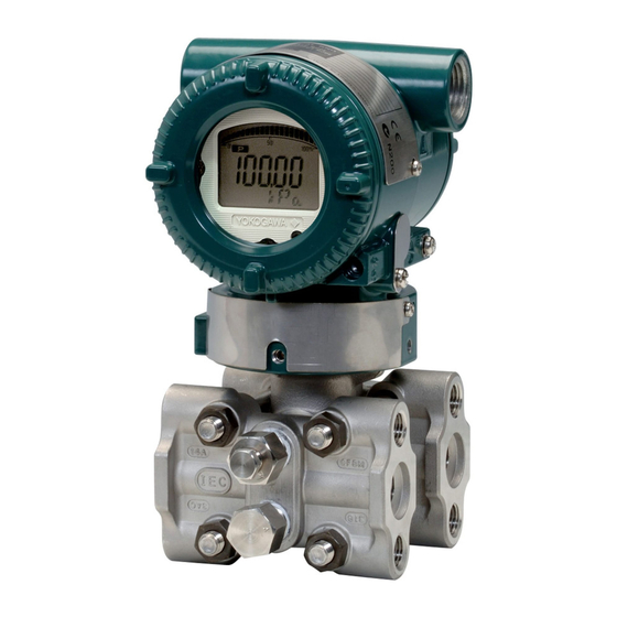
YOKOGAWA DpharpEJX vigilantplant EJX910A Manuals
Manuals and User Guides for YOKOGAWA DpharpEJX vigilantplant EJX910A. We have
4
YOKOGAWA DpharpEJX vigilantplant EJX910A manuals available for free PDF download: User Manual, Installation Manual
YOKOGAWA DpharpEJX vigilantplant EJX910A User Manual (139 pages)
Fieldbus Communication Type
Brand:
YOKOGAWA
| Category:
Transmitter
| Size: 0 MB
Table of Contents
Table of Contents
2
1 Introduction
7
Regarding this Manual
7
Safe Use of this Product
8
Warranty
9
ATEX Documentation
9
2 Handling Cautions
11
Installation of an Explosion-Protected Instrument
11
FM Approval
11
CSA Certification
13
CENELEC ATEX Certification
14
3 About Fieldbus
16
Outline
16
Internal Structure of EJX910A
16
System/Network Management VFD
16
Function Block VFD
16
Logical Structure of each Block
17
Wiring System Configuration
17
4 Getting Started
18
Connection of Devices
18
Host Setting
19
Bus Power on
20
Integration of DD
20
Reading the Parameters
20
Continuous Record of Values
21
Generation of Alarm
21
5 Configuration
22
Network Design
22
Network Definition
22
Definition of Combining Function Blocks
23
Setting of Tags and Addresses
24
Communication Setting
25
VCR Setting
25
Function Block Execution Control
26
Block Setting
26
Link Object
26
Trend Object
27
View Object
27
Function Block Parameters
31
6 Explanation of Basic Items
32
Outline
32
Setting and Changing Parameters for the Whole Process
32
SENSOR Transducer Block
32
Functional Block
32
Block Mode
33
Functions Relating to Differential Pressure
33
Functions Relating to Static Pressure
34
Functions Relating to External Temperature
35
Simulation Function
36
Functions Relating to Capsule and Amplifier Temperature
36
Block_Err
37
Xd_Error
37
FLOW Transducer Block
37
Outline of the Functions
37
Block Mode
37
Calculation of the Flow
37
Flow Unit/Decimal Point Digit
38
Flow Type Selection
38
Block_Err
38
Xd_Error
38
LCD Transducer Block
38
Outline of the Functions
38
Block Mode
38
Display Contents of the Integral Indicator
38
Example Displays of the Integral Indicator
39
Procedure to Set the Built-In Display
40
Units that Can be Displayed on the LCD by the Automatic Link Function
42
AI Function Block
44
Function Blocks
44
Block Mode
44
Io_Opts
44
Status_Opt
44
Out_D
44
Basic Parameters of the AI Block
45
7 In-Process Operation
46
Mode Transition
46
Generation of Alarm
46
Indication of Alarm
46
Alarms and Events
46
Simulation Function
47
8 Device Information
48
Device Status
48
Status of each Parameter in Failure Mode
51
9 Parameter Lists
53
Resource Block
53
SENSOR Transducer Block
55
FLOW Transducer Block
59
LCD Transducer Block
62
Al Function Block
64
Parameter Names Cross Reference
66
10 General Specifications
69
Standard Specifications
69
Optional Specifications (for Explosion Protected Type)
69
Appendix 1. Signal Characterizer (Sc) Block
72
A1.1 Schematic Diagram of Signal Characterizer Block
72
A1.2 Input Section
74
A1.2.1 Determining the Mode
74
A1.2.2 Judging BLOCK_ERR
74
A1.3 Line-Segment Factor Determination Section
75
A1.3.1 Conditions for Configuring Valid Coefficients
75
A1.4 List of Signal Characterizer Block Parameters
77
A1.5 Application Example
78
A1.5.1 Input Compensation
78
A1.5.2 Calorie Flow Compensation
78
A1.5.3 Backward Control
78
Appendix 2. Integrator (It) Block
80
A2.1 Schematic Diagram of Integrator Block
80
A2.2 Input Process Section
81
A2.2.1 Determining Input Value Statuses
81
A2.2.2 Converting the Rate
81
A2.2.3 Converting Accumulation
82
A2.2.4 Determining the Input Flow Direction
82
A2.3 Adder
83
A2.3.1 Status of Value after Addition
83
A2.3.2 Addition
83
A2.4 Integrator
84
A2.5 Output Process
85
A2.5.1 Status Determination
85
A2.5.2 Determining the Output Value
86
A2.5.3 Mode Handling
87
A2.6 Reset
88
A2.6.1 Reset Trigger
88
A2.6.2 Reset Timing
88
A2.6.3 Reset Process
89
A2.7 List of Integrator Block Parameters
90
Appendix 3. Input Selector (Is) Block
92
A3.1 Input Selector Function Block Schematic
92
A3.2 Input Section
94
A3.2.1 Mode Handling
94
A3.2.2 MIN_GOOD Handling
94
A3.3 Selection
95
A3.3.1 OP_SELECT Handling
95
A3.3.2 SELECTION Handling
96
A3.4 Output Processing
102
A3.4.1 Handling of SELECTED
102
A3.4.2 out Processing
103
A3.4.3 Status_Opts
104
A3.5 List of Input Selector Block Parameters
104
A3.6 Application Example
105
Appendix 4. Arithmetic (Ar) Block
106
A4.1 Arithmetic Function Block Schematic
106
A4.2 Input Section
107
A4.2.1 Main Inputs
107
A4.2.2 Auxiliary Inputs
107
A4.2.3 Input_Opts
108
A4.2.4 Relationship between the Main Inputs and PV
108
A4.3 Computation Section
109
A4.3.1 Computing Equations
109
A4.3.2 Compensated Values
109
A4.3.3 Average Calculation
109
A4.4 Output Section
109
A4.4.1 Mode Handling
110
A4.4.2 Status Handling
110
A4.5 List of the Arithmetic Block Parameters
111
Appendix 5. Pid Block
113
A5.1 Function Diagram
113
A5.2 Functions of PID Block
113
Algorithm
113
A5.4.2 PID Control Parameters
113
A5.5 Control Output
113
A5.7 Control Action Bypass
113
A5.8 Feed-Forward
113
A5.10 Bumpless Transfer
113
A5.11 Setpoint Limiters
113
A5.4.1 PV-Proportional and -Derivative Type PID (I-PD) Control Algorithm
116
A5.17.1Shed_Opt
120
A5.18 Alarms
120
A5.18.1Block Alarm (BLOCK_ALM)
120
A5.18.2Process Alarms
120
A5.19 Example of Block Connections
121
A5.20 View Object for PID Function Block
121
Appendix 6. Link Master Functions
123
A6.1 Link Active Scheduler
123
A6.2 Link Master
123
A6.3 Transfer of las
124
A6.4 LM Functions
125
A6.5 LM Parameters
126
A6.5.1 LM Parameter List
126
A6.5.2 Descriptions for LM Parameters
128
A6.6 Faqs
130
Appendix 7. Software Download
131
A7.2 Specifications
131
A7.1 Benefits of Software Download
131
A7.3 Preparations for Software Downloading
131
A7.4 Software Download Sequence
132
A7.5 Download Files
132
A7.6 Steps after Activating a Field Device
133
A7.7 Troubleshooting
134
A7.8 Resource Block's Parameters Relating to Software Download
134
Software Download
134
A7.9 System/Network Management VFD Parameters Relating to Software Download
136
A7.10 Comments on System/Network Management VFD Parameters
137
Relating to Software Download
137
Revision Record
139
Advertisement
YOKOGAWA DpharpEJX vigilantplant EJX910A User Manual (66 pages)
Multivariable Transmitters
Brand:
YOKOGAWA
| Category:
Transmitter
| Size: 3 MB
Table of Contents
Table of Contents
2
1 Introduction
5
Regarding this Manual
5
Safe Use of this Product
6
Warranty
7
ATEX Documentation
8
2 About the EJX910A Multivariable Transmitter
9
EJX910A Features
9
Initial Check and Installation Procedure
9
Flow Calculation
11
Auto Compensation Mode
11
Configuration Procedure for Auto Compensation Mode
12
Basic Mode
12
Configuration Procedure for Basic Mode
13
Calculation of the Basic Mode Parameters
14
3 Handling Cautions
17
Model and Specifications Check
17
Unpacking
17
Storage
17
Selecting the Installation Location
18
Pressure Connection
18
Waterproofing of Cable Conduit Connections
18
Restrictions on Use of Radio Transceivers
18
Insulation Resistance and Dielectric Strength Test
18
Installation of an Explosion-Protected Instrument
19
FM Approval
19
CSA Certification
20
CENELEC ATEX (KEMA) Certification
20
EMC Conformity Standards
23
Pressure Equipment Directive (PED)
23
Low Voltage Directive
24
4 Component Names
25
5 Installation
26
Precautions
26
Mounting
26
Changing the Process Connection
27
Swapping the High/Low-Pressure Side Connection
28
Rotating Pressure-Detector Section 180
28
Using the Communicator
28
Rotating Transmitter Section
29
Changing the Direction of Integral Indicator
29
6 Installing Impulse Piping
30
Impulse Piping Installation Precautions
30
Connecting Impulse Piping to a Transmitter
30
Routing the Impulse Piping
31
Impulse Piping Connection Examples
33
7 Wiring
34
Wiring Precautions
34
Selecting the Wiring Materials
34
Types of Output
34
Connection
35
Power Supply Wiring Connection
35
External Indicaror Connection
35
Communicator Connection
35
Check Meter Connection
35
External Temperature Connection
35
Wiring
35
Loop Configuration
35
Wiring Installation
36
RTD Cable Connection
36
Connecting Shielded Cable with Cable Gland
36
(External Temperature Input Code: -1, -2, -3, and -4)
36
Connecting Shielded Cable for Conduit Use (External Temperature Input Code: -B, -C, and -D)
38
Removing Shielded Cable with Cable Gland (External Temperature Input Code: -1, -2, -3, and -4)
38
Removing Shielded Cable for Conduit Use (External Temperature Input Code: -B, -C, -D)
38
Cable Connection RTD Terminal Box Side
38
Grounding
39
Pulse Output
40
8 Operation
41
Preparation for Starting Operation
41
Zero Point Adjustment
42
Adjusting Zero Point for Differential Pressure
42
Adjusting Zero Point for Static Pressure
43
Adjusting Zero Point for External Temperature
43
Starting Operation
43
Shutting down the Transmitter
44
Venting or Draining Transmitter Pressure-Detector Section
44
Draining Condensate
44
Venting Gas
44
9 Maintenance
45
Overview
45
Calibration Instruments Selection
45
Calibration
45
Pressure and Static Pressure
45
External Temperature (RTD)
46
Disassembly and Reassembly
48
Replacing the Integral Indicator
48
Replacing the CPU Board Assembly
49
Cleaning and Replacing the Capsule Assembly
49
Replacing the Process Connector Gaskets
51
Troubleshooting
51
Basic Troubleshooting
51
Troubleshooting Flowcharts
52
Alarms and Countermeasures
54
10 General Specifications
56
Standard Specifications
56
Model and Suffix Codes
60
Optional Specifications
60
Dimensions
64
YOKOGAWA DpharpEJX vigilantplant EJX910A User Manual (52 pages)
Multivariable Transmitter HART Communication Type
Brand:
YOKOGAWA
| Category:
Transmitter
| Size: 0 MB
Table of Contents
Table of Contents
2
1 Introduction
4
Regarding this Manual
4
Safe Use of this Product
5
Warranty
5
ATEX Documentation
6
Matching of Communicator DD and Instrument DD
7
2 Conditions of Communication Line
8
Interconnection between Dpharp and the HART Communicator
8
Communication Line Requirements
8
Power Supply Voltage and Load Resistance
8
3 Operation
9
Basic Operation of the 275 HART Communicator
9
Keys and Functions
9
Display
10
Calling up Menu Addresses
10
Entering, Setting, and Sending Data
11
Parameter Usage and Selection
12
Menu Tree
13
Basic Setup
18
Tag and Device Information
18
Process Variable Setup
18
Changing the Allocation to PV
18
Changing the Allocation to SV
18
Changing the Allocation to TV
18
Changing the Allocation to 4V
18
Keypad Input
19
Changing the Allocation to PV
19
Changing the PV Range
19
PV Unit
20
PV Damp
20
Units
20
Pres Unit
20
SP Unit
21
ET Unit
21
Flow Unit
22
Total Flow Unit
22
Output Signal Low Cut Mode Setup
23
Impulse Line Connection Orientation Setup
23
Detailed Setup
23
Signal Condition
23
Flow Setup
23
DP Setup
23
SP Setup
23
ET Setup
24
Total Flow
24
External Temperature Fixation Mode
24
User Unit Configuration for Total Flow
25
Integral Indicator Scale Setup
25
Display Selection
26
Cyclic Display
26
Display Resolution
26
User Setting of Engineering Unit and Scale
26
Burst Mode
27
Multidrop Mode
28
External Switch Mode
28
CPU Failure Burnout Direction and Hardware Write Protect
29
Simulation Mode
29
Basic Flow Calculation
32
Software Write Protection
34
Setting Password
35
Entering Password to Enable the Parameter Changes
35
Releasing Password
35
Software Seal
35
Alarm
36
Status Output
36
Pulse Output
37
DO Test
38
Diag/Service
40
Test Output
40
Sensor Trim
40
Auto Sensor Trim
41
Manual Sensor Trim
41
Sensor Trim for Static Pressure or External Temperature
42
Reset Trim Adjustment to Factory Setting
42
Trim Analog Output
43
4 Self-Diagnostics
45
Identify Problems by Using the Communicator
45
Checking with Integral Indicator
45
Alarms and Countermeasures
46
5 Parameter Summary
49
Advertisement
YOKOGAWA DpharpEJX vigilantplant EJX910A Installation Manual (57 pages)
EJX Series and EJA-E Series Differential Pressure and Pressure Transmitters
Brand:
YOKOGAWA
| Category:
Transmitter
| Size: 16 MB
Table of Contents
Table of Contents
1
1 Introduction
2
For Safe Use of Product
3
Warranty
5
ATEX Documentation
6
2 Handling Cautions
7
Model and Specifications Check
8
Selecting the Installation Location
8
Pressure Connection
8
Installation of an Explosion-Protected Instrument
8
EMC Conformity Standards
28
Pressure Equipment Directive (PED)
29
Safety Requirement Standards
30
3 Installation
31
Mounting
31
Mounting the Diaphragm Seals
31
Diaphragm Seals Installation Consideration
32
Mounting the Flushing Connection Ring
33
3.5 Affixing The Teflon Film
34
Rotating Transmitter Section
35
Changing the Direction of Integral Indicator
35
4 Installing Impulse Piping
36
Impulse Piping Installation Precautions
36
Routing the Impulse Piping
37
Impulse Piping Connection Examples
38
Process Piping Installation Precautions (EJ115)
39
5 Wiring
41
Wiring Precautions
41
Connections of External Wiring to Terminal Box
41
Power Supply Wiring Connection
42
Status Output Connection
42
Wiring
44
Wiring Installation
45
RTD Cable Connection (EJX910A/EJX930A)
46
Grounding
48
Power Supply Voltage and Load Resistance
48
6 Operation
49
Preparation for Starting Operation
49
Zero Point Adjustment
49
Local Parameter Setting
50
7 Errors and Countermeasures
52
Advertisement
Related Products
YOKOGAWA DPharp EJX930A
YOKOGAWA DpharpEJX vigilantplant EJX440A
YOKOGAWA DpharpEJX vigilantplant EJX110
YOKOGAWA DpharpEJX vigilantplant EJX210A
YOKOGAWA EJX Series
YOKOGAWA EJX610A
YOKOGAWA EJX115A
YOKOGAWA DPharp EJXC80A
YOKOGAWA DPharp EJXC50A
YOKOGAWA EJX110B
YOKOGAWA Categories
Measuring Instruments
Test Equipment
Transmitter
Controller
Media Converter
More YOKOGAWA Manuals
Login
Sign In
OR
Sign in with Facebook
Sign in with Google
Upload manual
Upload from disk
Upload from URL