
Related Manuals for YOKOGAWA DP harp EJX Series


Summary of Contents for YOKOGAWA DP harp EJX Series
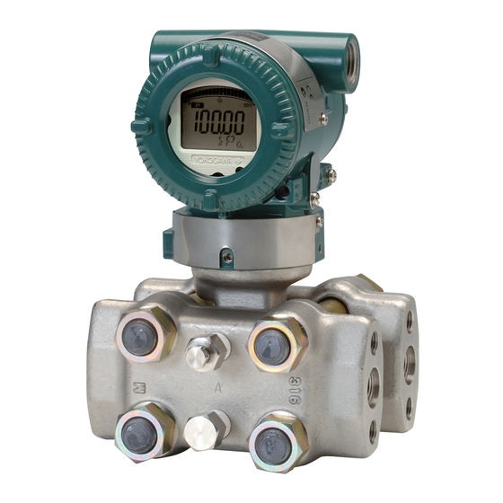
- Page 1 User’s Manual Differential Pressure and Pressure Transmitters EJ110, EJ120, EJ130, EJ310, EJ430, and EJ440 IM 01C25B01-01E IM 01C25B01-01E 21st Edition...
-
Page 2: Table Of Contents
Rotating Pressure-detector Section 180° ......... 4-3 4.4.2 Using the Communicator ..............4-3 Rotating Transmitter Section ................4-4 Changing the Direction of Integral Indicator ..........4-4 21st Edition: Nov. 2019 (YK) IM 01C25B01-01E All Rights Reserved, Copyright © 2004, Yokogawa Electric Corporation... - Page 3 Toc-2 Installing Impulse Piping ................. 5-1 Impulse Piping Installation Precautions ............5-1 5.1.1 Connecting Impulse Piping to a Transmitter ........5-1 5.1.2 Routing the Impulse Piping ..............5-3 Impulse Piping Connection Examples ............5-4 Wiring ......................6-1 Wiring Precautions ................... 6-1 Selecting the Wiring Materials .................
- Page 4 Functional Safety Manual (Document No.: TI 01C25A05-01EN or TI 01C25A05-21EN for option code SLT) and follow the instructions and procedures described there.The document can be downloaded from the website of Yokogawa. (Website address: https://www.yokogawa.com/solutions/products-platforms/field-instruments/) In order to satisfy the requirement of Safety Instrumented System, executing parameters setting is required.
-
Page 5: Introduction
TI 01C25A05-01EN or TI 01C25A05-21EN for option code SLT) and follow the instructions and NOTE procedures described there.The document can be downloaded from the website of Yokogawa. This manual describes the hardware (Website address: configurations of the transmitters listed in below. https://www.yokogawa.com/solutions/products-... -
Page 6: Regarding This Manual
Yokogawa’s injury. It may also be used to alert against unsafe written permission. practices. • Yokogawa makes no warranty of any kind with regard to this manual, including, but not limited IMPORTANT to, implied warranty of merchantability and fitness for a particular purpose. -
Page 7: Safe Use Of This Product
(f) Modification WARNING WARNING • The instrument must be installed by an • Yokogawa will not be liable for malfunctions engineer or technician who has an expert or damage resulting from any modification knowledge of this instrument. Operators are made to this instrument by the customer. - Page 8 (h) Authorized Representative in EEA • In relation to the CE Marking, The authorised representative for this product in the EEA (European Economic Area) is: Yokogawa Europe B.V. Euroweg 2, 3825 HD Amersfoort,The Netherlands Control of Pollution Caused by the Product This is an explanation for the product based on “Control of Pollution caused by Electronic Information...
-
Page 9: Warranty
- Use of the product in question in a location not conforming to the standards specified by Yokogawa, or due to improper maintenance of the installation location. - Failure or damage due to modification or repair by any party except Yokogawa or an approved representative of Yokogawa. - Malfunction or damage from improper relocation of the product in question after delivery. -
Page 10: Handling Cautions
<2. Handling Cautions> Handling Cautions Model and Specifications This chapter provides important information on how to handle the transmitter. Read this carefully before Check using the transmitter. The model name and specifications are written on The transmitters are thoroughly tested at the the name plate attached to the case. factory before shipment. -
Page 11: Selecting The Installation Location
<2. Handling Cautions> Pressure Connection (b) When storing the transmitter, repack it carefully in the packaging that it was originally shipped with. WARNING (c) If the transmitter has been used, thoroughly • Never loosen the process connector bolts clean the chambers inside the cover flanges, so when an instrument is installed in a process. that there is no process fluid remaining inside. -
Page 12: Insulation Resistance And Dielectric Strength Test
The voltage instrument may be hazardous to operate. Please should be applied as briefly as possible to verify contact Yokogawa before making any repair or that the insulation resistance is at least 20 MΩ. modification to an instrument. 4) After completing the test and being very careful not to touch exposed conductors disconnect the CAUTION insulation tester and connect a 100 kΩ resistor... -
Page 13: Fm Approval
Zone 0, it shall be installed such that, even in the event of rare incidents, an ignition source due to impact and/or friction sparks is excluded. Note 4. Maintenance and Repair Only personnel authorized by Yokogawa Electric Corporation can repair the equipment. IM 01C25B01-01E... - Page 14 Fieldbus and OUNDATION PROFIBUS PA type) Rev.2: July 16, 2019 Doc. No.: IFM022-A12 Yokogawa Electric Corporation 1 to 5 V (Low Power type) Note 2. Wiring • All wiring shall comply with National Electrical Model: EJX Series Date: October 22, 2003...
-
Page 15: Csa Certification
• Amb. Temp.:–50* to 60°C • The instrument modification or parts * –15°C when /HE is specified. replacement by other than authorized • Process Temperature: 120°C max. representative of Yokogawa Electric [For CSA E60079] Corporation is prohibited and will void • Applicable Standard: CAN/CSA E60079-11, Factory Mutual Explosionproof Approval. - Page 16 • Ambient Temperature: –50* to 75°C (T4), replacement by other than authorized –50* to 80°C (T5), –50* to 75°C (T6) * –15°C when /HE is specified. representative of Yokogawa Electric • Supply Voltage: 42 V dc max. Corporation and Yokogawa Corporation 32 V dc max. (F...
-
Page 17: Atex Certification
Yokogawa Electric type, suitable for the conditions of use and Corporation and Yokogawa Corporation of correctly installed. America is prohibited and will void Canadian • Unused apertures shall be closed with Standards Explosionproof Certification. - Page 18 • The instrument modification or parts EN 60079-1:2014, EN60079-31:2014 replacement by other than authorized • Type of Protection and Marking Code: representative of Yokogawa Electric Ex db IIC T6...T4 Gb, Ex tb IIIC T85°C Db Corporation is prohibited and will void • Group: II DEKRA Intrinsically safe Certification.
- Page 19 • The instrument modification or parts Pressure Transmitters replacement by other than an authorized SUPPLY + Representative of Yokogawa Electric Voltmeter Corporation is prohibited and will void the Power Supply certification. • The fasteners used to fasten the transmitter –...
- Page 20 Flameproof Type • The instrument modification or parts replacement by other than authorized EJX/EJA-E Series pressure transmitters with representative of Yokogawa Electric optional code /KU22 or /V1U1 can be selected Corporation is prohibited and will void ATEX the type of protection ATEX Flameproof, intrinsically safe.
- Page 21 Ex ic IIC T4 Gc IP66 Tamb -30(-15) TO 60°C The instrument modification or parts replacement MAX. PROCESS TEMP. 120°C Ui=30V, Ci=27.6nF, Li=0µH by other than an authorized Representative of Yokogawa Electric Corporation is prohibited and WARNING will void the certification. POTENTIAL ELECTROSTATIC CHARGING HAZARD - SEE USER’S MANUAL F0209.ai MODEL: Specified model code.
-
Page 22: Iecex Certification
The installation must be in representative of Yokogawa Electric accordance with the description about the Corporation is prohibited and will void IECEx type of protection in this instruction manual. - Page 23 Note 2. Wiring • The instrument modification or parts • In hazardous locations, the cable entry replacement by other than authorized devices shall be of a certified flameproof representative of Yokogawa Electric type, suitable for the conditions of use and Corporation is prohibited and will void IECEx correctly installed. certification.
-
Page 24: Emc Conformity Standards
• WARNING: WHEN THE AMBIENT TEMP.≥65°C, USE CAUTION HEAT-RESISTING CABLE AND CABLE GLAND ≥90°C. To meet EMC regulations, Yokogawa • Take care not to generate mechanical recommends that customers run signal wiring sparking when accessing to the instrument through metal conduits or use shielded twisted-... -
Page 25: Eu Rohs Directive
2-16 <2. Handling Cautions> 2.12 EU RoHS Directive Capsule PS.V Model V(L) Category* code (bar) (bar.L) Applicable standard: EN 50581 EJA110E M, H, V Applicable production sites are shown below. 0.01 EJ110 F, L The condition of the RoHS compliant production Article 4, EJX110A Paragraph 3... -
Page 26: Component Names
<3. Component Names> Component Names Vertical impulse piping type Pressure-detector section Terminal box cover Cover flange Horizontal impulse piping type External indicator conduit connection (Note 1) Conduit connection Zero- adjustment screw (Note 2) Push button (Note 1) Slide switch (See section 7.6) Integral indicator (Note 1) -
Page 27: Installation
<4. Installation> Installation Precautions Before installing the transmitter, read the cautionary notes in section 2.4, “Selecting the Installation Location.” For additional informations and limitations according to the selected model, suffix 57 mm 54 mm 51 mm and option codes, please find information in each F0401.ai General Specifications sheet. Figure 4.1 Process Connector Impulse Piping Connection Distances for Differential Pressure Transmitters IMPORTANT Figure 4.1 and 4.2 shows the mounting of the... -
Page 28: Changing The Process Connection
<4. Installation> Changing the Process Vertical pipe mounting (Process connector downside) Connection Transmitter The transmitter is shipped with the process mounting bolt connection specified at the time of ordering. To Mounting bracket change the process connection, the drain (vent) 50 mm(2-inch) pipe plug must be repositioned. U-bolt nut To reposition a drain (vent) plug, use a wrench to U-bolt slowly and gently unscrew it. -
Page 29: Swapping The High/Low-Pressure Side Connection
<4. Installation> Swapping the High/Low- 4.4.2 Using the Communicator pressure Side Connection This method is applicable only to the Model EJ110, EJ120, and EJ130. IMPORTANT With a communicator, you can change which process connection is used as the high-pressure This section is applicable only for EJ110, side without mechanically rotating the pressure- EJ120, and EJ130 differential detector section 180 as described in subsection... -
Page 30: Rotating Transmitter Section
<4. Installation> Rotating Transmitter Section Vertical impulse piping type The transmitter section can be rotated Pressure-detector section approximately 360° and can be fixed at any angle Stopper within the above range. (The direction of the rotation is depending on the configuration of the instrument.) Note that there is a stopper which prevents the transmitter section from being rotated more than 360°. -
Page 31: Installing Impulse Piping
<5. Installing Impulse Piping> Installing Impulse Piping Impulse Piping Installation (2) Changing the Process Connector Piping Connections (Figure 4.1) (for differential Precautions pressure transmitters) The impulse piping that connects the process The impulse piping connection distances can be outputs to the transmitter must convey the process changed between 51 mm, 54 mm and 57 mm by pressure accurately. - Page 32 <5. Installing Impulse Piping> Pipe-Mounting Type 3-Valve Manifold Direct-Mounting Type 3-Valve Manifold (Figure 5.2) (Figure 5.3) 1) Screw nipples into the connection ports on the 1) Mount the 3-valve manifold on the transmitter. transmitter side of the 3-valve manifold, and (When mounting, use the two gaskets and the into the impulse piping connecting ports on four bolts provided with the 3-valve manifold.
-
Page 33: Routing The Impulse Piping
<5. Installing Impulse Piping> 5.1.2 Routing the Impulse Piping (3) Impulse Piping Slope The impulse piping must be routed with only an (1) Process Pressure Tap Angles upward or downward slope. Even for horizontal If condensate, gas, sediment or other extraneous routing, the impulse piping should have a slope of material in the process piping gets into the impulse at least 1/10 to prevent condensate (or gases) from... -
Page 34: Impulse Piping Connection Examples
<5. Installing Impulse Piping> (7) Preventing Freezing Liguid Steam If there is any risk that the process fluid in the Orifice Condensate pot impulse piping or transmitter could freeze, use a valve steam jacket or heater to maintain the temperature of the fluid. Union or flange NOTE After completing the connections, close the valves on the process pressure taps (main 3-valve manifold... -
Page 35: Wiring
<6. Wiring> Wiring Wiring Precautions Connections of External Wiring to Terminal Box IMPORTANT ● Terminal Configuration • Lay wiring as far as possible from electrical noise sources such as large capacity transformers, motors, and power supplies. • Remove the electrical connection dust cap before wiring. -
Page 36: External Indicator Connection
<6. Wiring> ■ 1 to 5 V output, HART Transmitter terminal box Connect the HART communicator or Power supply configuration tool to the SUPPLY - and VOUT – (+) terminals. (Use hooks.) Load resistance is not necessary for 1 to 5 V output. Transmitter terminal box F0601.ai Power supply Voltmeter Figure 6.2 Power Supply Wiring Connection –... -
Page 37: Status Output Connection
<6. Wiring> 6.3.5 Status Output Connection (2) 4 to 20 mA output, Intrinsically Safe Type With the intrinsically safe type, a safety barrier must When option code /AL is specified, connect the be included in the loop. external wiring as shown in Figure 6.5. To configure and activate the process alarm Hazardous Location Nonhazardous Location function and status output, it is necessary to set Transmitter terminal box... -
Page 38: Wiring Installation
<6. Wiring> ■ Four wire connection (2) Flameproof Type Fasten the negative side wiring of both power Wire cables through a flameproof packing adapter, supply and signal line to the SUPPLY - terminal. or use a flameproof metal conduit. Hazardous Location Nonhazardous Location ■ Wiring cable through flameproof packing adapter. Transmitter terminal box Distributor (Power supply unit) Flameproof packing adapter Flexible metal conduit... -
Page 39: Grounding
<6. Wiring> Grounding Grounding is always required for the proper operation of transmitters. Follow the domestic electrical requirements as regulated in each country. For a transmitter with a built-in lightning protector, grounding should satisfy ground resistance of 10Ω or less. Ground terminals are located on the inside and outside of the terminal box. -
Page 40: Operation
<7. Operation> Operation Preparation for Starting Venting Gas from the Transmitter Pressure- detector Section Operation • Since the piping in the example of figure 7.1 This section describes the operation procedure for is constructed to be self-venting, no venting the EJ110, EJ120 and EJ130 as shown operation is required. If it is not possible to in figure 7.1a (vertical impulse piping type, high- make the piping self-venting, refer to subsection pressure connection: right side) when measuring... - Page 41 <7. Operation> PARAM C60:SELF CHECK ERROR Vent plug (Fill plug) communication error Tap valve DATA DIAG PRNT Communication error Self-diagnostic error (Faulty wiring) (Faulty transmitter) Stop valve F0703.ai Figure 7.2 BT200 Display Using the integral indicator • If the wiring system is faulty, the display stays blank.
-
Page 42: Zero Point Adjustment
<7. Operation> Zero Point Adjustment 7.2.1 Adjusting Zero Point for Differential Pressure Transmitters After completing preparations for operating the Before adjusting zero point, make sure that the transmitter, adjust the zero point. equalizing valve is open. Zero point adjustment can be done by turning the transmitter’s zero-adjustment screw or by using the communicator. -
Page 43: Starting Operation
<7. Operation> Use a slotted screwdriver to turn the zero- IMPORTANT adjustment screw. Turn the screw clockwise to increase the output or counterclockwise to • Remove the communicator from the terminal decrease the output. The zero point adjustment can box, and confirm that none of the terminal be made with a resolution of 0.01% of the setting screws are loose. -
Page 44: Venting Or Draining Transmitter Pressure-Detector Section
<7. Operation> Venting or Draining 7.5.2 Venting Gas Transmitter Pressure- 1) Gradually open the vent screw to vent gas from the transmitter pressure-detector section. (See detector Section figure 7.6.) Since this transmitter is designed to be self- 2) When the transmitter is completely vented, draining and self-venting with vertical impulse close the vent screw. -
Page 45: Local Parameter Setting
<7. Operation> Local Parameter Setting 7.6.1 Local Parameter Setting (LPS) Overview WARNING Parameter configuration by the zero-adjustment screw and push button (integral indicator code E) offers easy and quick setup for parameters of The local push button on the integral indicator Loop test, Tag number, Unit, LRV, URV, Damping, must not be used in a hazardous area. When Output mode (linear/square root), Display out it is necessary to use the push button, operate 1, and Re-range by applying actual pressure... - Page 46 <7. Operation> screw Process Zero adjustment Measurement Display push Activate LPS mode push 1. Loop Test Select Output Current Run/Cancel 2. Tag Number Edit Tag number Save/Cancel the value push 3. Press Unit Select Press unit Save/Cancel the value 4. Press LRV Edit Press LRV Save/Cancel the value push...
-
Page 47: Activating Local Parameter Setting
<7. Operation> 7.6.2 Activating Local Parameter Setting Press the push button on the integral indicator to activate the Local Parameter Setting mode. The transmitter will exit automatically from the Local Parameter Setting mode if no operation is carried out for 10 minutes. 7.6.3 Parameter Setting Review Current setting value for the below parameters are shown sequentially by each press of the push button. -
Page 48: Loop Test Configuration
<7. Operation> 7.6.4 Loop Test Configuration Loop test configuration can be changed as below. Output current value (4 mA, 12 mA or 20 mA) for Loop test can be selected by turning the zero-adjustment screw. Run ?/ Cancel ? Blinking Blinking [Available loop test] Select by the push button 4mA: 0% output 12mA: 50% output 20mA: 100% output screw Select by the push button or turning the push extemal adjustment... -
Page 49: Pressure Lrv/Urv Configuration
7-10 <7. Operation> 7.6.7 Pressure LRV/URV Configuration Pressure LRV and URV can be set. The number for each digit is changed by turning the zero-adjustment screw and set by pressing the push button. Please refer to 7.6.8 Damping Time Constant Configuration for how to change the numerical value. When the setting is out of the limit, an alarm will be generated. 7.6.8 Damping Time Constant Configuration The damping time constant for the amplifier assembly can be set. Quick Response Parameter is automatically set to ON when the damping time constant is set to less than 0.5 seconds. -
Page 50: Re-Range By Applying Actual Pressure (Lrv/Urv)
7-11 <7. Operation> 7.6.11 Re-range by applying actual Note 1: Wait until the pressure inside the pressure-detector section has stabilized before proceeding to the next pressure (LRV/URV). step. Note 2: If the pressure applied to the transmitter exceeds the This feature allows the lower and upper range previous LRV (or URV), the integral indicator may values to be setup with the actual input applied. -
Page 51: Abort Configuration
7-12 <7. Operation> 7.6.14 Abort Configuration 7.6.15 Local Parameter Setting Lock To disable parameter changes by the Local 7.6.14.1 Abort Configuration (Menu) Parameter Setting there are three different ways. Hold down the push button for over 2 seconds to Locked features exit the Local Parameter Setting mode. Communication Parameter •... -
Page 52: Maintenance
<8. Maintenance> Maintenance Overview Calibration Use the procedure below to check instrument WARNING operation and accuracy during periodic maintenance or troubleshooting. Since the accumulated process fluid may be 1) Connect the instruments as shown in figure 8.1 toxic or otherwise harmful, take appropriate care and warm up the instruments for at least five to avoid contact with the body or inhalation of minutes (ten minutes for EJ310.) vapors when draining condensate or venting gas from the transmitter pressure-detector section... - Page 53 <8. Maintenance> Table 8.1 Instruments Required for Calibration Name Yokogawa-recommended Instrument Remarks Power supply Model SDBT or SDBS distributor 4 to 20 mA DC signal Load resistor Model 2792 standard resistor [250 Ω ±0.005%, 3 W] Load adjustment resistor [100 Ω ±1%, 1 W] Voltmeter Model 2501 A digital multimeter Accuracy (10V DC range): ±(0.002% of rdg + 1 dgt) Digital Model MT220 precision digital manometer...
-
Page 54: Disassembly And Reassembly
Tweezers with its integral indicator removed, or from adding an integral indicator to a transmitter. If such modification is absolutely required, contact CAUTION Yokogawa. Precautions for ATEX Flameproof Type This subsection describes the procedure for Transmitters replacing an integral indicator. (See figure 8.3) • Flameproof type transmitters must be, as... -
Page 55: Replacing The Cpu Board Assembly
<8. Maintenance> ■ Removing the Integral Indicator 3) Disconnect the output terminal cable (cable with brown connector at the end). When doing 1) Remove the cover. this, lightly press the side of the CPU assembly 2) While supporting the integral indicator with one connector and pull the cable connector to hand, loosen its two mounting screws. -
Page 56: Cleaning And Replacing The Capsule Assembly
7) Remove the capsule assembly. one of a different measurement range, contact 8) Clean the capsule assembly or replace with a Yokogawa. new one. The user is permitted, however, to replace a ■ Reassembling the Capsule Assembly capsule assembly with another of the same measurement range. -
Page 57: Replacing The Process Connector Gaskets
Removing and Mounting the Pressure- and remedy the problem. Since some problems detector Section have complex causes, these flow charts may not identify all. If you have difficulty isolating or IMPORTANT correcting a problem, contact Yokogawa service personnel. If you remove the vent/drain plugs when disassembling EJ130 and EJ440 8.5.1 Basic Troubleshooting transmitters, install the plugs again before... -
Page 58: Troubleshooting Flowcharts
Is there any pressure leak? Fix pressure leaks, paying particular attention to connections for impulse piping,pressure-detector section, etc. Is there continuity through the transmitter loop wiring? Do the loop numbers match? Find/correct broken conductor or wiring error. Contact Yokogawa service personnel. F0807.ai IM 01C25B01-01E... - Page 59 Is zero point calibration? adjusted correctly? Refer to Section 8.2 when selecting instruments for calibration. Adjust the zero point. Contact Yokogawa service personnel. Is output adjusted correctly? F0808.ai Adjust the output. Contact Yokogawa service personnel. F0809.ai IM 01C25B01-01E...
-
Page 60: Alarms And Countermeasures
<8. Maintenance> 8.5.3 Alarms and Countermeasures Table 8.3 Alarm Message Summary Output Operation Indicator Cause Countermeasure during Error None AL. 01 Sensor problem. Outputs the signal (Hold, High, or Replace capsule when error CAP. ERR Low) set with parameter. keeps appearing even after Capsule temperature sensor restart. -
Page 61: General Specifications
<9. General Specifications> General Specifications Please refer to the following General Specifications list for the specifications, model, suffix and option codes, and external dimensions of each product. The General Specifications can be downloaded from the website of Yokogawa. Website address: https://www.yokogawa.com/solutions/products-platforms/field-instruments/ ■ General Specifications List Model Document Title Document No. EJX110A Differential Pressure Transmitter GS 01C25B01-01EN EJX120A Differential Pressure Transmitter GS 01C25B03-01EN EJX130A Differential Pressure Transmiter GS 01C25B04-01EN EJX210A Flange Mounted Differential Pressure Transmitter GS 01C25C01-01EN EJX310A... -
Page 62: Revision Information
Rev-1 Revision Information Title : Differential Pressure and Pressure Transmitters EJ110, EJ120, EJ130, EJ310, EJ430, and EJ440 Manual No. : IM 01C25B01-01E Edition Date Page Revised Item Mar. 2004 — New publication 15th Oct. 2014 • Add information for 1 to 5 V output. 2.9.1 •... - Page 63 Rev-2 Edition Date Page Revised Item 19th Oct. 2018 • Add S2. • Add descriptions in “Regarding This Manual.” 1-2 to 1-4 • Add WARINING marks. Add notes in (c). Add (i) • Delete “1.3 ATEX Documentation.” • Correct current value of dielectric strength test. 10 mA -> 25 mA 2-4 to 2-5 2.9.1 a.
Need help?
Do you have a question about the DP harp EJX Series and is the answer not in the manual?
Questions and answers