
Subscribe to Our Youtube Channel
Related Manuals for YOKOGAWA DPHarp EJX210B


Summary of Contents for YOKOGAWA DPHarp EJX210B
- Page 1 User’s Manual EJX210B Flange Mounted Differential Pressure Transmitter IM 01C27C01-01EN IM 01C27C01-01EN 13th Edition Y okogawa Electric Corporation...
-
Page 2: Table Of Contents
2.13 EU RoHS Directive ..................2-10 Component Names .................. 3-1 Installation ....................4-1 Precautions ....................... 4-1 Mounting ......................4-1 Rotating Transmitter Section ................4-1 13th Edition: July 2021 (YK) IM 01C27C01-01EN All Rights Reserved, Copyright © 2010, Yokogawa Electric Corporation... - Page 3 Toc-2 Changing the Direction of Integral Indicator ..........4-2 Changing the direction of the antenna ............4-2 Mounting the Flushing Connection Ring ............4-3 4.6.1 Mounting to Pressure Detector Section ..........4-3 4.6.2 Mounting to Process Flange .............. 4-3 Affixing the Teflon Film ..................4-4 Installing Impulse Piping .................
- Page 4 Toc-3 8.3.3 Parameters for Wireless Communication ........8-10 8.3.4 Tag and Device Information ............. 8-10 8.3.5 Unit ....................8-11 8.3.6 Range Change ................. 8-11 8.3.7 Output Signal Low Cut Mode Setup ..........8-11 8.3.8 Integral Indicator Setup ..............8-12 8.3.9 Unit for Displayed Temperature ............
-
Page 5: Introduction
It may also be used to be reproduced in any form without Yokogawa’s alert against unsafe practices. written permission. • Yokogawa makes no warranty of any kind with regard to this manual, including, but not limited IMPORTANT to, implied warranty of merchantability and fitness for a particular purpose. -
Page 6: Safe Use Of This Product
If these instructions are not heeded, the protection provided by this instrument may be impaired. In instrument. this case, Yokogawa cannot guarantee that the instrument can be safely operated. Please pay Notice special attention to the following points:... -
Page 7: Radio Wave
(e) Modification Before using this instrument, ensure that neither a premises radio station nor specified • Yokogawa will not be liable for malfunctions or low power radio station for mobile object damage resulting from any modification made identification systems is in use nearby. to this instrument by the customer. If this instrument causes radio wave... -
Page 8: Warranty
- Use of the product in question in a location not conforming to the standards specified by Yokogawa, or due to improper maintenance of the installation location. - Failure or damage due to modification or repair by any party except Yokogawa or an approved representative of Yokogawa. - Malfunction or damage from improper relocation of the product in question after delivery. -
Page 9: Control Of Pollution Caused By The Product
<1. Introduction> Control of Pollution Caused by the Product This is an explanation for the product based on “Control of Pollution caused by Electronic Information Products” in the People’s Republic of China. 電子情報製品汚染制御管理弁法 (中国版RoHS) 产品中有害物质或元素的名称及含量 产品中有害物质或元素的名称及含量 有害物质 型号 部件名称 铅 汞... -
Page 10: Handling Cautions
For more details, please refer to the following No antenna is provided for URL. Amplifier https://www.yokogawa.com/qr-code housing code 9. QR Code is a registered trademark of DENSO WAVE INCORPORATED. Process connector Unpacking Keep the transmitter in its original packaging to prevent it from being damaged during shipment. -
Page 11: Storage
<2. Handling Cautions> Storage Selecting the Installation Location The following precautions must be observed when storing the instrument, especially for a long period. The transmitter is designed to withstand severe environmental conditions. However, to ensure (a) Select a storage area which meets the following that it will provide years of stable and accurate conditions: performance, take the following precautions when... -
Page 12: Pressure Connection
<2. Handling Cautions> Restrictions on Use of Radio (b) Ambient Temperature Avoid locations subject to wide temperature Transceivers variations or a significant temperature gradient. If the location is exposed to radiant heat from IMPORTANT plant equipment, provide adequate thermal insulation and/or ventilation. Although the transmitter has been designed to resist high frequency electrical noise, if a radio (c) Ambient Atmosphere transceiver is used near the transmitter or its... -
Page 13: Installation Of An Explosion-Protected Instrument
Please circuiting battery connection terminals. Leave contact Yokogawa before making any repair or this resistor connected at least one second to modification to an instrument. discharge any static potential. Do not touch the terminals while it is discharging. -
Page 14: Fm Approval
WARNING – DO NOT OPEN WHEN CL II, III, DIV 1, 2 ATMOSPHERE IS PRESENT WARNING – USE ONLY BATTERY PACK YOKOGAWA F9915MA OR F9915NS WARNING – THE BATTERY PACK CAN BE REPLACED IN A HAZARDOUS LOCATION. THE BATTERY PACK HAS SURFACE RESISTIVITY GREATER THAN 1G OHM AND MUST BE PROPERLY INSTALLED IN THE ENCLOSURE OF THE TRANSMITTER. -
Page 15: Csa Certification
Class III, Division 1 F0205.ai Note 1. Model EJX Series differential, gauge, Note 3. Battery Pack and absolute pressure transmitters with • Use only YOKOGAWA battery pack optional code /CS17 are applicable for use in hazardous locations F9915MA or F9915NS. • No. CSA10CA2325443X Note 4. Special Conditions for safe use •... - Page 16 POTENTIAL ELECTROSTATIC CHARGING HAZARD - SECURE DISTANCE WARNING OF 100MM FROM ANTENNA. USE ONLY BATTERY PACK YOKOGAWA F9915MA OR F9915NS. POTENTIAL ELECTROSTATIC CHARGING HAZARD - SEE USER'S MANUAL. F0208.ai Note 5. Maintenance and repair MODEL: Specified model code.
-
Page 17: Iecex Certification
IEC 60079-0, IEC 60079-11, IEC 60079-28 comply with the construction described in the • Certificate number: IECEx KEM10.0074X certificate documentation. • Specific Ex marking: Ex ia op is IIC T4 Ga Only personnel authorized by Yokogawa Electric • Ambient temperature: –50°C ≤ Ta ≤ +70°C Corporation can repair the equipment. • Process temperature: –50°C ≤ Tp ≤ +120°C • Enclosure: IP66/IP67 in accordance with only IEC 60529 •... -
Page 18: Emc Conformity Standards
Radio and (3) Operation Telecommunication Please confirm that a installation region fulfils a CAUTION standards, require additional regulatory information and approvals, contact to Yokogawa Electric • The temperature and pressure of fluid should Corporation. be maintained at levels that are consistent with normal operating conditions. 2.12.1 Radio Equipment Directive (RE) • The ambient temperature should be... -
Page 19: Fcc Compliance
2-10 <2. Handling Cautions> 2.12.2 FCC compliance This radio transmitter IC Number 8999A-WIC001 / 8999A-WIC013 has been approved by Industry This equipment contains transmitter module FCC ID: Canada to operate with the antenna types SGJ-WFC001 listed below with the maximum permissible gain SGJ-WFC014 indicated. -
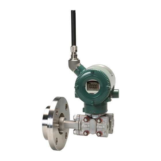
Page 20: Component Names
<3. Component Names> Component Names Antenna Ground terminal Zero-adjustment screw Process connection (Low pressure side) Integral indicator Cover flange RF assembly Process connector Bolt CPU assembly Mounting Write protection switch Slide ● Terminal configuration screw switch (External powered type) Transmitter section E WR Power supply terminal +... -
Page 21: Installation
<4. Installation> Installation Precautions IMPORTANT Before installing the transmitter, read the cautionary Please use a gasket with an inside diameter notes in Section 2.4, “Selecting the Installation (ød) that is greater than the diameter of the Location.” For additional information on the diaphragm seal. -
Page 22: Changing The Direction Of Integral Indicator
<4. Installation> Changing the direction of IMPORTANT the antenna Do not rotate the transmitter section more than Adjust the direction of the antenna to be in the the above limit. upright position. To change the installation angle, follow the procedure below. 1) Loosen the two mounting screws at the bottom of the antenna by using a 2.5 mm Allen wrench (see Figure 4.3). The screws might come off... -
Page 23: Mounting The Flushing Connection Ring
<4. Installation> Mounting the Flushing 4.6.2 Mounting to Process Flange Connection Ring Tighten the bolts to completely close the gap between the ring and the pressure detector section. 4.6.1 Mounting to Pressure Detector The mating flange, gasket, stud bolts and nuts are Section to be procured by the customer. The flushing connection ring is mounted to high pressure side pressure detector section as shown in Figure 4.5. -
Page 24: Affixing The Teflon Film
<4. Installation> Affixing the Teflon Film The FEP Teflon option includes a teflon film and fluorinated oil. Before mounting the transmitter to the process flange, affix the teflon film as follows: IMPORTANT 1) Position the diaphragm so that the diaphragm is in a upward position. 2) Pour the fluorinated oil on the diaphragm and gasket area covering it completely and evenly. Be careful not to scratch the diaphragm or change the its shape. 3) Affix the teflon film over the diaphragm and gasket area. -
Page 25: Installing Impulse Piping
<5. Installing Impulse Piping> Installing Impulse Piping Impulse Piping Installation (2) Tightening the Process Connector Mounting Bolts Precautions After connecting the impulse line, tighten the The impulse piping that connects the process process connector mounting bolts uniformly. outputs to the transmitter must convey the process ( Apply a torque of 39 ~ 49N·m { 4 ~ 5kgf·m} ) pressure accurately. -
Page 26: Impulse Piping Connection Examples
<5. Installing Impulse Piping> Impulse Piping Connection Examples Figure 5.2 shows examples of typical impulse piping connections. Before connecting the transmitter to the process, study the transmitter installation location, the process piping layout, and the characteristics of the process fluid (corrosiveness, toxicity, flammability, etc.), etc. and make appropriate changes and additions to the connection configurations. -
Page 27: Wiring
<6. Wiring> Wiring Mounting Antenna and Wiring An antenna is not attached to the transmitter. The following provides the instructions for mounting the antenna and installing the remote antenna and wiring using antenna extension cable. IMPORTANT The antenna connector is covered with a cap at the time of delivery. -
Page 28: Mounting External Antenna And Wiring Antenna Extension Cable
<6. Wiring> 6.1.2 Mounting External Antenna and Mounting Procedure of External Wiring Antenna Extension Cable Antenna 1. Fix the bracket by U-bolt and nut to 50 mm (2- 6.1.2.1 Mounting of External Antenna inch) pipe. Mount the external antenna at the proper location 2. - Page 29 Antenna extension cable 1: 3 m Antenna extension cable 1: 3 m Protect by self-bonding tape Transmitter body Transmitter body F0604.ai Figure 6.4 Wiring the antenna extension cable CAUTION Use the dedicated antenna extension cable provided by Yokogawa as accessories for the transmitters. IM 01C27C01-01EN...
-
Page 30: Mounting Of Surge Protective Device And Wiring
<6. Wiring> Grounding 6.1.2.3 Mounting of Surge Protective Device and Wiring When using the antenna extension cable with an Mount an surge protective device between the arrestor, Class C grounding with the grounding extension cables and connect the grounding cable resistance of 10 Ω is required. Always ground the to the grounding terminal of the surge protective transmitter case in accordance with national and... -
Page 31: Power Supply Wiring Precautions
<6. Wiring> Power Supply Wiring Connection of the External Precautions Power Source Terminal For the external powered type, connect the power IMPORTANT supply wiring to + and − terminals. If the power supply cable has shield wires, connect the cable • All threaded parts must be treated with shield to the ground terminal. waterproofing sealant. (A non-hardening silicone group sealant is recommended.) Power supply terminal +... -
Page 32: Operation
<7. Operation> Operation Preparation for Starting Operation Open Tank The EJX210B flange mounted differential pressure transmitter measures the levels or densities of liquids. This section describes the operation procedure for the EJX210B as shown in Figure 7.1 when measuring a liquid level in an open tank. NOTE It is required to set security and network information to enable the transmitter to be... -
Page 33: Zero Point Adjustment
<7. Operation> ■ Verify and Change Transmitter Parameter ■ Using the Zero-adjustment screw Setting and Values Before adjusting zero point, make sure followings. The parameters related to the following items are • The External zero trim parameter minimum required to be set for operation, and set at (External Zero Trim) is “Trim on”. -
Page 34: Starting Operation
Provisioning work performs provisioning for each field wireless device using FieldMate and an ■ Preparation work prior to connecting to a infrared adapter. If use Yokogawa-recommended field wireless network infrared device for provisioning, set distance between the glass window surface to the infrared This transmitter does not need to be connected device within 30cm. - Page 35 <7. Operation> 2) Creating a provisioning information file Mounting battery pack or turning on the power The following provisioned information is stored in the provisioning information file. • Network ID Boot • Device tag • EUI64 Search failure for Pause (b) the specified time • Join key Infrared communication •...
-
Page 36: Shutting Down The Transmitter
<7. Operation> Venting or Draining (c) Confirm connecting status Transmitter Pressure- detector Section Since this transmitter is designed to be self- draining and self-venting with vertical impulse piping connections, neither draining nor venting will be required if the impulse piping is configured appropriately for self-draining or self-venting operation. F0708.ai If condensate (or gas) collects in the transmitter pressure-detector section, the measured pressure (d) Join may be in error. If it is not possible to configure the... -
Page 37: Venting Gas (Low Pressure Side)
<7. Operation> 7.6.3 Draining Condensate for Flushing Connection Ring 1) Gradually open the drain screw to drain from the flushing connection ring. 2) When the flushing connection ring is completely drained, close the drain screw. 3) Tighten the drain screw to a torque of 10 N·m {1 kgf·m}. When you loosen the drain screw, Drain plug the accumulated liquid(or gas) will be expelled in the direction of... -
Page 38: Venting Gas For Flushing Connection Ring
<7. Operation> 7.6.4 Venting Gas for Flushing Connection Ring 1) Gradually open the vent screw to vent gas from the flushing connection ring. 2) When the flushing connection ring is completely vented, close the vent screw. 3) Tighten the vent screw to a torque of 10 N·m {1 kgf·m}. Vent screw When you loosen the vent screw, the accumulated liquid(or drain) -
Page 39: Setting Parameters
Refer to the following website for the latest perform provisioning and have the transmitter join information on CF/DD and DeviceDTM. the field wireless network. <http://www.yokogawa.com/> This transmitter supports the OOB (out-of-band) CF (Capabilities File)/DD (Device Description) method using the infrared communication as a provisioning method. -
Page 40: Parameter Usage And Selection
<8. Setting Parameters> Setting Parameters IMPORTANT 8.3.1 Parameter Usage and Selection After setting and sending data with the field Before setting a parameter, please see the following wireless configuration tool or the device table for a summary of how and when each configuration tool, wait 30 seconds before parameter is used. turning off the transmitter. If it is turned off too soon, the settings will not be stored in the transmitter. -
Page 41: Function Block And Menu Tree
<8. Setting Parameters> 8.3.2 Function Block and Menu Tree (1) Function Block The function of this transmitter is shown below. A specific function might not be able to be used according to the field wireless configuration tool used. When the field wireless configuration tool of our recommendation is used, the software attached to the Field Wireless Integrated Gateway is necessary for setting the dotted line part. Refer to Subsection 9.2 “Calibration Instruments Selection” for the field wireless configuration tool of our recommendation. Online Menu (UAPMO) (Configuration) • UAP Option •... - Page 42 <8. Setting Parameters> Online Menu (continued) (AI1 DP) (Block Info) • Tag Description • Block Info • Block Mode • Dynamic Variables (Block Mode ) • Configuration • Mode.Target • Calibration • Mode.Actual • Others • Mode.Permitted • Mode.Normal (Process Value) (Dynamic Variables) •...
- Page 43 <8. Setting Parameters> Online Menu (continued) (AI2 SP) (Block Info) • Tag Description • Block Info • Block Mode • Dynamic Variables (Block Mode ) • Configuration • Mode.Target • Others • Mode.Actual • Mode.Permitted • Mode.Normal (Dynamic Variables) (Process Value) •...
- Page 44 <8. Setting Parameters> Online Menu (continued) (Block Info) (AI3 Temp) • Tag Description • Block Info • Block Mode • Dynamic Variables (Block Mode ) • Configuration • Mode.Target • Others • Mode.Actual • Mode.Permitted • Mode.Normal (Dynamic Variables) (Process Value) •...
- Page 45 <8. Setting Parameters> (2) Menu Tree The menu tree of the device configuration tool of our recommendation is shown below. Refer to Subsection 9.2 “Calibration Instruments Selection” for the device configuration tool of our recommendation. (Alerts) Menu (Online) (Device Configuration) (UAPMO) (Configuration) • Device Configuration • UAPMO • Configure/Setup • UAP Option • Other Faults Alert • Diagnostic • TRANSDUCER • Hardware Write Protect • Faults Non-compliance •...
- Page 46 <8. Setting Parameters> Menu (Online) Device Configuration (continued) (continued) (Block Info) (AI2 SP) • Configure/Setup • Tag Description (Block Mode) • Mode.Target • Mode.Actual • Mode.Permitted • Mode.Normal (Configuration) (Block Mode) • Block Mode • Mode.Target • Concentrator OID • Mode.Actual •...
- Page 47 <8. Setting Parameters> Menu (Online) (continued) (UAPMO) (Diagnostics) (Diagnostic) (Diagnostic Configuration) • UAPMO • Device Diagnostics • Diagnostic Status • Diagnostic.Other Faults • Diagnostic Status Detail.1 • Diagnostic.Faults Non-Compliance • Diagnostic Status Detail.2 • Diagnostic.Faults Process Influence • Diagnostic Switch •...
-
Page 48: Parameters For Wireless Communication
8-10 <8. Setting Parameters> 8.3.3 Parameters for Wireless (6) LCD display Communication The following steps describe how to set LCD display. (1) Network Information 1. On/Off of display Concentrator object block : Configuration When “Enable” in LCD Mode is selected, the Allows confirming the network information. LCD displays a set of screens to be shown and turns off for the specified time based on LCD (2) Update Time Intermittent Time, and the display keeps the... -
Page 49: Unit
8-11 <8. Setting Parameters> • When changing the device information, input 8.3.7 Output Signal Low Cut Mode Setup the information based on the following limitation Low cut mode can be used to stabilize the output on the number of characters. signal near the zero point. -
Page 50: Integral Indicator Setup
8-12 <8. Setting Parameters> 8.3.8 Integral Indicator Setup 8.3.9 Unit for Displayed Temperature The following three displays are available for When the instrument is shipped, the temperature units are set to C (Centigrade). Follow the the Integral Indicator: differential pressure, static pressure, and temperature. procedure below to change this setting. The following three variables can be displayed on •... -
Page 51: Zero Point Adjustment And Span Adjustment
8-13 <8. Setting Parameters> 8.3.11 Zero Point Adjustment and Span To match current input and output value, Adjustment follow procedure Like tank level measurement that is Each EJX-B Series Differential Pressure/Pressure impossible to set actual level to zero, output Transmitter is characterized by factory. But there value is adjustment to actual level by other are some errors caused by environment and measurement using glass gauge. - Page 52 8-14 <8. Setting Parameters> Using External Zero-adjustment Screw (2) Span Adjustment External Zero-adjustment parameter (External Span Adjustment is function to change the Zero Trim) can set permission or prohibition to input and output characteristic that assumed adjustment by External Zero-adjustment Screw. the bottom value (zero point) of measurement range as a standard.
-
Page 53: Software Write Protection
8-15 <8. Setting Parameters> • Procedure to call up the calibration 8.3.12 Software Write Protection adjustment parameter (Cal Cmd). Hardware write protection and software write AI1 block: Cal Cmd: CAL_HIGH protection functions are available for this Set the upper limit of the measurement range transmitter. -
Page 54: Switching To Silence Mode
8-16 <8. Setting Parameters> CAUTION After setting the deep sleep mode by infrared device configuration tool, keep the infrared port of device away from any other infrared signals. NOTE • Transmitter becomes the stop state after setting deep sleep mode and cannot reply any request from the device configuration tool via wireless communication. •... -
Page 55: Self-Diagnostics
8-17 <8. Setting Parameters> Self-Diagnostics UAPMO block: Diagnostic Status Any of the four categories (Check function, 8.4.1 Identify Problems by Using the Maintenance required, Failure, and Off Device Configuration Tool specification) according to NAMUR NE107* is supplied to Diagnostic Status of each diagnostic First, check Diagnostic Status of the self-diagnostic result. -
Page 56: Alert Report
8-18 <8. Setting Parameters> 8.4.2 Alert Report EJX generates alert information related to Diagnostic Status and automatically sends to a field wireless gateway. To use this function, the following alert setting is necessary. When “Out of Service” for Diagnostic Status alert is required, choose “FALSE” for [Out of Service.Alert Disable] in the UAPMO block. Refer to the field wireless gateway User’s Manual for the setting procedure to obtain the alert information from the gateway. - Page 57 Not applicable for the diagnostic regarding AI2 object and static pressure measurement. NOTE A critical low battery alarm may be happened even if battery power of device is remaining. When unexpected alarm is happened, please restart the device by power off/on or Field Wireless Device Restart Tool. Field Wireless Device Restart Tool is available in "Downloads" tab at following website: https://www.yokogawa.com/solutions/products-platforms/field-instruments/. IM 01C27C01-01EN...
-
Page 58: Checking With Integral Indicator
8-20 <8. Setting Parameters> 8.4.3 Checking with Integral Indicator NOTE If an error is detected by running self-diagnostics, an error number is displayed on the integral indicator. If there is more than one error, the error number changes at three-second intervals. See Table 9.3 regarding the error codes. -
Page 59: Maintenance
<9. Maintenance> Maintenance Overview Calibration Use the procedure below to check instrument WARNING operation and accuracy during periodic maintenance or troubleshooting. Since the accumulated process fluid may be 1) Insert the battery pack or turn on the power toxic or otherwise harmful, take appropriate care and then perform provisioning to have the to avoid contact with the body or inhalation of transmitter join the Field Wireless Network vapors when draining condensate or venting gas... - Page 60 <9. Maintenance> Table 9.1 Instruments Required for Calibration Name Yokogawa-recommended Instrument Remarks Provisioning • FieldMate (R2.02.01 or later) device tool • Provisioning Device Tool • Infrared adapter certified by Yokogawa Supplier: ACTiSYS,Product name: IrDA InfraRed USB Adaptor Product number: IR224UN Field wireless • Field Wireless Integrated Gateway attached Software...
-
Page 61: Disassembly And Reassembly
<9. Maintenance> Disassembly and Table 9.2 Tools for Disassembly and Reassembly Reassembly Tool Quantity Remarks Phillips JIS B4633, No. 2 screwdriver This section describes procedures for disassembly Slotted and reassembly for maintenance and component screwdriver replacement. Allen wrenches JIS B4648 One each, nominal 3, 4 and 2.5 mm Allen CAUTION... -
Page 62: Replacing The Rf Assembly
<9. Maintenance> 5) Replace the cover. Power 9.4.3 Replacing the CPU Assembly cable This subsection describes how to replace the CPU assembly (see Figure 9.2). Press Forward ■ Removing the CPU assembly Stud 1) Remove the cover. Zero Remove the integral indicator and the RF Integral indicator Boss adjustment... -
Page 63: Replacing The Process Connector Gaskets
<9. Maintenance> 9.4.5 Replacing the Battery Pack IMPORTANT Regarding the transmitter with intrinsically safe Confirm that the zero-adjustment screw pin is approval, the battery pack can be replaced without removing the device in hazardous area. placed properly in the groove on the bracket prior to tightening the two bosses. If it is not, the zero- ■... -
Page 64: Replacing The Batteries
<9. Maintenance> 9.4.6 Replacing the Batteries 9.4.7 Handling Batteries The batteries in the battery pack can be replaced. This battery pack uses two primary lithium/ Batteries are not installed when shipped from the thionyl chloride batteries. Each battery contains factory. Assemble the battery pack as follows. approximately 5 grams of lithium, for a total of 10 grams in each pack. -
Page 65: Replacing The Power Supply Module
Take a right action on waste batteries, because the correcting a problem, contact Yokogawa service collection system in the EU on waste batteries are personnel. regulated. 9.5.1 Basic Troubleshooting... -
Page 66: Troubleshooting Flowcharts
Check/correct Check transmitter. environmental conditions. Is the Field Wireless Network Operating conditions setting correct? Reconnect to the Field Wireless Check/correct operating Network. conditions. F0906.ai Figure 9.5.1 Basic Flow and Self-Diagnostics Contact Yokogawa service personnel. F0907.ai IM 01C27C01-01EN... - Page 67 Provide lagging and/or cooling, or allow Adjust the zero point. adequate ventilation. Contact Yokogawa service personnel. Were appropriate F0908.ai instruments used for calibration? Refer to Section 9.2 "Calibration Instruments Selection".
-
Page 68: Errors And Countermeasures
9-10 <9. Maintenance> 9.5.3 Errors and Countermeasures Table 9.3 Error Message Summary (Causes and Actions) Release/ Factory recovery Integral NAMUR Diagnostic Diagnostic Status Detail Cause conditions Action indicator category Status (except restart) FC_SENSOR_FAIL Recovers only when AUTO FR_SENSOR_FAIL RECOVER is ON and within the range Pressure sensor... - Page 69 9-11 <9. Maintenance> Release/ Factory recovery Integral NAMUR Diagnostic Diagnostic Status Detail Cause conditions Action indicator category Status (except restart) DP_TRIM_SPAN_OUTSIDE Pressure span Recovers Check adjustment when span the span AL.53 variable outside adjustment adjustment P. ADJ of range variable/point variable for returns within the Pressure.
- Page 70 When the device detects “AL01 CAP.ERR” and “AL02 AMP.ERR”, the LCD display stays on regardless of the status in LCD mode. NOTE A critical low battery alarm may be happened even if battery power of device is remaining. When unexpected alarm is happened, please restart the device by power off/on or Field Wireless Device Restart Tool. Field Wireless Device Restart Tool is available in "Downloads" tab at following website: https://www.yokogawa.com/solutions/products-platforms/field-instruments/. IM 01C27C01-01EN...
- Page 71 9-13 <9. Maintenance> Table 9.4 Error Message Summary (Output Actions) Output actions Factory Integral Diagnostic Capsule NAMUR Diagnostic Status Detail Static Indicator Status Pressure Temp Temp category Pressure Value Value FC_SENSOR_FAIL Output value Output value (hold value) (hold value) FR_SENSOR_FAIL Output status Output status Normal action...
- Page 72 9-14 <9. Maintenance> Output actions Factory Integral Diagnostic Capsule NAMUR Diagnostic Status Detail Static Indicator Status Pressure Temp Temp category Pressure Value Value DP_OUTSIDE_LIMIT Output value Output value (calculated in (calculated in a normal way) a normal way) AL. 10 Output status Output status Normal action Normal action...
- Page 73 9-15 <9. Maintenance> Output actions Factory Integral Diagnostic Capsule NAMUR Diagnostic Status Detail Static Indicator Status Pressure Temp Temp category Pressure Value Value AL. 30 Environmental DP_OUTSIDE_RANGE Normal action Normal action Normal action Normal action RANGE conditions out Bit 22 of device SP_OUTSIDE_RANGE AL.
- Page 74 10-1 <10. Parameter Summary> 10. Parameter Summary Table 10.1 Parameter Object Attribute Default Label Description Handling value Version Revision Indicates the application revision of EJX This revision UAPMO when the application software is downloaded. block Static Revision Indicates the revision level of the fixed parameters of UAP Used, for example, to check whether parameters have been change.
- Page 75 10-2 <10. Parameter Summary> Object Attribute Default Label Description Handling value Power Supply Indicates the predicted battery level and the power UAPMO Status supply method. block 0 = external power supply (continued) 1 = battery level 75% or more 2 = battery level 25% ~ 75% 3 = battery level 25% or less EHType Available to write note into this parameter.
- Page 76 10-3 <10. Parameter Summary> Object Attribute Default Label Description Handling value Faults Sensor or The On/Off or priority for Faults Sensor or actuator 1. TRUE UAPMO actuator Alert Alert can be set. 2. 15 block 1. O n/Off setting (continued) 0 = FALSE, 255 =TRUE 2. Alert report priority: 0 to 15 Faults Electronics The On/Off or priority for Faults Electronics Alert can 1.
- Page 77 10-4 <10. Parameter Summary> Object Attribute Default Label Description Handling value PUB_ITEM_MAX Maximum PUB_ITEM value PUB_ITEM_NUM PUB_ITEM number block PUB_ITEM Indicates the PUB_ITEM information. The following (continued) shows the components 1. ObjectID 2. AttributeID 3. AttributeIndex 4. Size Tag Description Memo field available to write anything.
- Page 78 10-5 <10. Parameter Summary> Object Attribute Default Label Description Handling value Special Order ID Displays the special order number, if applicable. TRANSDUCER Unit Sel1 Selects whether to automatically apply the unit to the Auto block word for the parameter for which the unit display is (continued) selected, or apply the characters that are written to Display Unit1.
- Page 79 10-6 <10. Parameter Summary> Object Attribute Default Label Description Handling value Lower Limit Indicates the lower limit (LRL) for the pressure. PV Range Sets the measurement range. EU at 100% block 1. EU at 100% : Indicates input value of the upper = 100 (continued) limit.
- Page 80 10-7 <10. Parameter Summary> Object Attribute Default Label Description Handling value T Zero Cmp Parameter to select the temperature zero shift compensation mode block 0 = OFF : Does not perform temperature zero shift (continued) compensation. 1 = ON : Performs temperature zero shift compensation.
- Page 81 10-8 <10. Parameter Summary> Object Attribute Default Label Description Handling value PV Range Sets the measurement range. 1. EU at 1. EU at 100% : Indicates input value of the upper 100% = block limit. 25000.000000 (continued) 2. EU at 0% : Indicates input value of the lower limit. EU at 0% 3.
- Page 82 10-9 <10. Parameter Summary> Object Attribute Default Label Description Handling value Block Mode A universal parameter to indicate the block’s operation 1. Target = status. O/S, Auto, and Man can be selected. Auto block 1. Target : Specify Al object mode. 2.
- Page 83 10-10 <10. Parameter Summary> Table 10.2 Diagnostic Status Detail[0] Diagnostic Status Diagnostic Status Detail Description NAMUR assignment bit DiagnosticDetail_1 FC_SENSOR_FAIL C sensor frequency error Bit26 FR_SENSOR_FAIL R sensor frequency error Bit26 CAP_T_SENSOR_FAIL Capsule temperature sensor failure Bit26 CAP_EEPROM_FAIL Capsule EEPROM failure Bit26 CAP_EEP_IRREGULAR CAP EEPROM version not correct...
- Page 84 11-1 <11. General Specifications> General Specifications Please refer to the following General Specifications sheet for the specifications, model, suffix and option codes, and external dimensions of each product. The General Specifications can be downloaded from the website of Yokogawa. Website address: https://www.yokogawa.com/solutions/products-platforms/field-instruments/ General Specifications List Model Document Title Document No. EJX110B, EJX310B, EJX430B Differential Pressure Transmitter GS 01C25B01-01EN EJX210B Flange Mounted Differential Pressure Transmitter GS 01C25C01-01EN EJX510B, EJX530B Absolute and Gauge Pressure Transmitters...
- Page 85 Rev-1 Revision Information Title : EJX210B Flange Mounted Differential Pressure Transmitter Manual No. : IM 01C27C01-01EN Edition Date Page Revised Item Aug. 2010 — Release of ISA100.11a protocol Apr. 2011 — • Adapted to device configuration tool with infrared communication function. • Part number change Battery pack: F9915MA → F9915NQ,Delete F9915MX Battery: A1133EB → F9915NR Delete battery case part number Dec.
Need help?
Do you have a question about the DPHarp EJX210B and is the answer not in the manual?
Questions and answers