Table of Contents
Advertisement
Advertisement
Table of Contents

Related Manuals for Fluke 9140


Summary of Contents for Fluke 9140
- Page 1 Hart Scientific 9140 Dry-well Calibrator User’s Guide Rev. 5B1702...
- Page 2 Fluke Corporation, Hart Scientific Division 799 E. Utah Valley Drive • American Fork, UT 84003-9775 • USA Phone: +1.801.763.1600 • Telefax: +1.801.763.1010 E-mail: support@hartscientific.com www.hartscientific.com Subject to change without notice. • Copyright © 2005 • Printed in USA Rev. 5B1702...
-
Page 3: Table Of Contents
Table of Contents 1 Before You Start ......1 Symbols Used ......1 Safety Information . - Page 4 8 Digital Communication Interface ....33 9 Test Probe Calibration ..... . 39 Temperature Set-point .
- Page 5 10 Calibration Procedure ..... . 43 10.1 Calibration Points ......43 10.2 Calibration Procedure .
- Page 6 Figure 8 9140 Back Panel ......13 9140 Front Panel ......14 Inserts available for the 9140 block assembly .
- Page 7 International Electrical Symbols ..... 1 Table 2 9140 controller communications commands....36 Table 3...
-
Page 8: Before You Start
Before You Start Symbols Used Table 1 lists the symbols used on the instrument or in this manual and the meaning of each symbol. Table 1 International Electrical Symbols Symbol Description AC (Alternating Current) AC-DC Battery Complies with European Union directives Double Insulated Electric Shock Fuse... -
Page 9: Safety Information
9140 Dry-well Calibrator User’s Guide Symbol Safety Information Use the instrument only as specified in this manual. Otherwise, the protection provided by the instrument may be impaired. Refer to the safety information below and throughout the manual. The following definitions apply to the terms “Warning” and “Caution”. - Page 10 ing power such as storage in a low humidity temperature chamber operat- ing at 50°C for 4 hours or more. • DO NOT use this instrument for any application other than calibration work. The instrument was designed for temperature calibration. Any other use of the instrument may cause unknown hazards to the user.
-
Page 11: Cautions
9140 Dry-well Calibrator User’s Guide ELECTRICAL SHOCK • These guidelines must be followed to ensure that the safety mechanisms in this instrument will operate properly. This instrument must be plugged into a 115 VAC, 60Hz (230 VAC, 50Hz optional), AC only electric outlet. -
Page 12: Authorized Service Centers
Authorized Service Centers Please contact one of the following authorized Service Centers to coordinate service on your Hart product: Fluke Corporation, Hart Scientific Division 799 E. Utah Valley Drive American Fork, UT 84003-9775 Phone: +1.801.763.1600 Telefax: +1.801.763.1010 E-mail: support@hartscientific.com... - Page 13 22 Jianguomenwai Dajie Chao Yang District Beijing 100004, PRC CHINA Phone: +86-10-6-512-3436 Telefax: +86-10-6-512-3437 E-mail: xingye.han@fluke.com.cn Fluke South East Asia Pte Ltd. Fluke ASEAN Regional Office Service Center 60 Alexandra Terrace #03-16 The Comtech (Lobby D) 118502 SINGAPORE Phone: +65 6799-5588 Telefax: +65 6799-5588 E-mail: antng@singa.fluke.com...
-
Page 14: Introduction
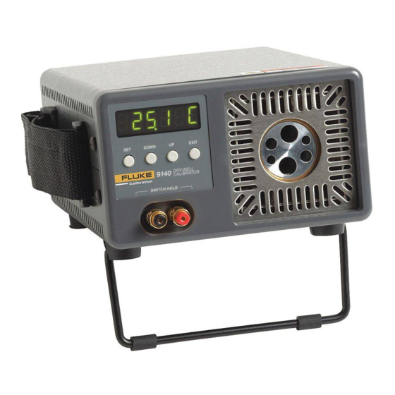
The Hart Scientific 9140 Mid-Range Field Calibrator may be used as a portable instrument or bench top temperature calibrator for calibrating thermocouple and RTD temperature probes. The 9140 is small enough to use in the field, and accurate enough to use in the lab. -
Page 15: Specifications And Environmental Conditions
Specifications and Environmental Conditions Specifications The following table lists the specifications for this instrument. Accuracy speci- fications are applicable for a one-year calibration interval. In line with normal prudent metrology practices, Hart Scientific recommends a short-cycle interval of six months for new units during the first year. Power Ambient Temperature Operating Range... -
Page 16: Warranty
• altitude does not effect the performance or safety of the unit Warranty Fluke Corporation, Hart Scientific Division (Hart) warrants this product to be free from defects in material and workmanship under normal use and service for a period as stated in our current product catalog from the date of shipment. -
Page 17: Quick Start
Unpack the dry-well carefully and inspect it for any damage that may have oc- curred during shipment. If there is shipping damage, notify the carrier immediately. Verify that the following components are present: • 9140 Dry-well • Insert • Insert Removal Tool • Power Cord •... -
Page 18: Setting The Temperature
User’s Guide dry-well will turn on and begin to heat to the previously programmed tempera- ture set-point. The front panel LED display will indicate the actual dry-well temperature. Setting the Temperature Section 7.2 explains in detail how to set the temperature set-point on the cali- brator using the front panel keys. -
Page 19: Parts And Controls
Fan - The fan inside the calibrator runs continuously when the unit is being op- erated to provide cooling for the instrument. It has two speeds, a slow speed for control operation and a faster speed for rapid cooling. Slots at the top and Figure 1 9140 Back Panel... -
Page 20: Front Panel
SET – Used to display the next parameter in the menu and to store parameters to the displayed value. DOWN – Used to decrement the displayed value of parameters. UP – Used to increment the displayed value. Figure 2 9140 Front Panel on page 14. -
Page 21: Constant Temperature Block Assembly
• Insert C (1/4” comparison block): 6 1/4” holes Insert “A” 1/16" 1/4" 1/2" 3/8" 3/8" 3/16" 1/8" Figure 3 Inserts available for the 9140 block assembly Insert “B” 1/4" 1/4" 3/16" 3/8" 3/16" 1/4" 5 Parts and Controls Constant Temperature Block Assembly Insert “C”... - Page 22 9140 Dry-well Calibrator User’s Guide • Insert D (comparison block): 2 each at 3 mm, 4 mm, and 6 mm...
-
Page 23: General Operation
Press the “UP” or “DOWN” key to change units. Switching to 230 V Operation The 9140 is switchable from 115 VAC to 230 VAC 50/60 Hz. Switching the voltage can change the calibration, so it is recommended to recalibrate the unit after changing the input voltage. -
Page 24: Setting The Temperature
User’s Guide • Using the same straight slot screwdriver, move the heater switch to dis- play “230V”. See the rear panel drawing in NOTE: If the heater switch and the fuse holder do not both read 230V when complete, the unit will either not heat or only heat at a fraction of its capacity. If not done properly, the unit could become damaged and void the calibration and warranty. - Page 25 6 General Operation Calibrating Probes Using the same hole for the reference thermometer and the test probe may have better results. This however requires switching the probes which takes more time. One must allow a few minutes after inserting the probes for the tempera- ture to stabilize before making measurements.
-
Page 26: Controller Operation
Controller Operation This chapter discusses in detail how to operate the dry-well temperature con- troller using the front control panel. Using the front panel key-switches and LED display the user may monitor the well temperature, set the temperature set-point in degrees C or F, monitor the heater output power, adjust the control- ler proportional band, and program the calibration parameters, operating pa- rameters, and serial interface configuration. -
Page 27: Figure 4 Controller Operation Flowchart
9140 Dry-well Calibrator User’s Guide Figure 4 Controller Operation Flowchart... -
Page 28: Set-Point Value
100.0 C Access set-point memory 1. 100. To change to another set-point memory press “UP” or “DOWN”. 4. 300. Press “SET” to accept the new selection and access the set-point value. Accept selected set-point memory 7.2.2 Set-point Value The set-point value may be adjusted after selecting the set-point memory and pressing “SET”. -
Page 29: Scan
User’s Guide Un= F Scan The scan rate can be set and enabled so that when the set-point is changed the dry-well heats or cools at a specified rate (degrees per minute) until it reaches the new set-point. With the scan disabled the dry-well heats or cools at the maximum possible rate. -
Page 30: Temperature Display Hold
Temperature Display Hold The 9140 has a display hold function which allows action of an external switch to freeze the displayed temperature and stop the set-point from scanning. This is useful for testing thermal switches and cutouts. This section explains the functions available for operating the temperature hold feature. -
Page 31: Switch Test Example
User’s Guide sistor. The calibrator measures the voltage at the red terminal and interprets +5V as open and 0V as closed. 7.4.4 Switch Test Example This section describes a possible application for the temperature hold feature and how the instrument is set up and operated. Suppose you have a thermal switch which is supposed to open at about 75°C and close at about 50°C and you want to test the switch to see how accurate and repeatable it is. -
Page 32: Proportional Band
is. With good control stability the percent heating power should not fluctuate more than ±1% within one minute. The heater power display is accessed in the secondary menu. Press “SET” and “EXIT” simultaneously and release. The heater power will be displayed as a percentage of full power. - Page 33 User’s Guide The temperature stability of the well and response time depend on the width of the proportional band. If the band is too wide the well temperature will deviate excessively from the set-point due to varying external conditions. This is be- cause the power output changes very little with temperature and the controller cannot respond very well to changing conditions or noise in the system.
-
Page 34: Controller Configuration
7 Controller Operation Controller Configuration Controller Configuration The controller has a number of configuration and operating options and calibra- tion parameters which are programmable via the front panel. These are ac- cessed from the secondary menu after the proportional band function by pressing “SET”. -
Page 35: Sample Period
User’s Guide 7.6.1.2 ALPHA This probe parameter refers to the average sensitivity of the probe between 0 and 100°C. The value of this parameter is set at the factory for best instrument accuracy. 7.6.1.3 DELTA This probe parameter characterizes the curvature of the resistance-temperature relationship of the sensor. -
Page 36: Sample Period
4800 b Press “SET” to set the baud rate to the new value or “EXIT” to abort the opera- tion and skip to the next parameter in the menu. 7.8.1 Sample Period The sample period is the next parameter in the serial interface parameter menu. The sample period is the time period in seconds between temperature measure- ments transmitted from the serial interface. -
Page 37: Linefeed
User’s Guide 7.8.1.2 Linefeed The final parameter in the serial interface menu is the linefeed mode. This pa- rameter enables (on) or disables (off) transmission of a linefeed character (LF, ASCII 10) after transmission of any carriage-return. The linefeed parameter is indicated by, Press “SET”... -
Page 38: Digital Communication Interface
Digital Communication Interface The dry-well calibrator is capable of communicating with and being controlled by other equipment through the digital serial interface. With a digital interface the instrument may be connected to a computer or other equipment. This allows the user to set the set-point temperature, monitor the temperature, and access any of the other controller functions, all using remote communications equipment. -
Page 39: Baud Rate
The current baud rate value will then be displayed. The baud rate of the 9140 serial communications may be programmed to 300, 600, 1200, 2400, 4800, or 9600 baud. The baud rate is pre-programmed to 1200 baud. Use “UP”... -
Page 40: Interface Commands
8 Digital Communication Interface Interface Commands face commands are discussed in Section. All commands are ASCII character strings terminated with a carriage-return character (CR, ASCII 13). Interface Commands The various commands for accessing the calibrator functions via the digital in- terfaces are listed in this section (see Table 2). - Page 41 User’s Guide Table 2 9140 controller communications commands Command Command Description Format Display Temperature Read current set-point s[etpoint] Set current set-point to n s[etpoint]=n Read temperature t[emperature] Read temperature units u[nits] Set temperature units: u[nits]=c/f Set temperature units to Celsius...
- Page 42 Table 3 9140 controller communications commands continued Command Command Description Format Set serial linefeed mode: lf[eed]=on/of[f] Set serial linefeed mode to on lf[eed]=on Set serial linefeed mode to off lf[eed]=of[f] Miscellaneous Other Commands Read firmware version number *ver[sion] Read structure of all commands...
-
Page 43: Test Probe Calibration
Test Probe Calibration For optimum accuracy and stability, allow the calibrator to warm up for 10 minutes after power-up and then allow adequate stabilization time after reach- ing the set-point temperature. After completing operation of the calibrator, al- low the well to cool by setting the temperature to 100°C for one-half hour before switching the power off. -
Page 44: Calibration Of Multiple Probes
For best results, insert probes the full depth of well. 9.2.2 Heating and Cooling Rates Figures 7 calibrator. show typical heating cooling rates of the 9140 dry-well... -
Page 45: Stabilization And Accuracy
WARNING: DO NOT remove inserts when heating or when the unit is hot. 9.2.3 Stabilization and Accuracy The stabilization time of the dry-well calibrator will depend on the conditions and temperatures involved. Typically the test well will be stable to 0.1°C within 5 minutes of reaching the set-point temperature as indicated by the display. - Page 46 User’s Guide timate stability will be achieved 10 to 20 minutes after reaching the set temperature. Inserting a cold probe into a well will require another period of stabilizing de- pending on the magnitude of the disturbance and the required accuracy. For ex- ample, inserting a .25 inch diameter room temperature probe into a sleeve at 300°C will take 5 minutes to be within 0.1°C of its settled point and will take 10 minutes to achieve maximum stability.
-
Page 47: Calibration Procedure
Calibration Procedure Sometimes the user may want to calibrate the dry-well to improve the tempera- ture set-point accuracy. Calibration is done by adjusting the controller probe calibration constants R0 , ALPHA, and DELTA so that the temperature of the dry-well as measured with a standard thermometer agrees more closely with the set-point. -
Page 48: Compute R & Alpha
User’s Guide delta - Measured temperature using thermometer. - Value of set-point resistance from display of 9140. (Press SET and DOWN at the same time.) where and R and R and R 10.2.2 Compute R rzero alpha delta is the new value of DELTA computed above 5. -
Page 49: Accuracy & Repeatability
b. Press SET then use the UP or DOWN keys until the correct numerical setting is displayed. Press SET to accept the new value. c. Repeat step b. for ALPHA and DELTA. 10.2.3 Accuracy & Repeatability 1. Check the accuracy of the dry-well at various points over the calibration range. -
Page 50: Maintenance
Maintenance • The calibration instrument has been designed with the utmost care. Ease of operation and simplicity of maintenance have been a central theme in the product development. Therefore, with proper care the instrument should require very little maintenance. Avoid operating the instrument in an oily, wet, dirty, or dusty environment. -
Page 51: Troubleshooting
Solutions Troubleshooting If problems arise while operating the 9140, this section provides some sugges- tions that may help you solve the problem. A wiring diagram is also included. 12.1 Troubleshooting Problems, Possible Causes, and Solutions In the event that the instrument appears to function abnormally, this section may help to find and solve the problem. -
Page 52: Ce Comments
9140 Dry-well Calibrator User’s Guide Problem The display shows an error code Temperature can- not be set above a certain point Display is reading incorrectly Display flickers when the instru- ment is turned off The instrument does not reach temperature 12.2...
Need help?
Do you have a question about the 9140 and is the answer not in the manual?
Questions and answers