
Related Manuals for Fluke 914 Series


Summary of Contents for Fluke 914 Series
- Page 1 Test Equipment Depot - 800.517.8431 - 99 Washington Street Melrose, MA 02176 TestEquipmentDepot.com 914X Series Field Metrology Well User’s Guide Revision 7A1901-EN...
-
Page 3: Table Of Contents
Table of Contents Before You Start ...............1 Introduction ....................1 Unpacking ....................2 Symbols Used ................... 3 Safety Information ..................4 1.4.1 Warnings ......................5 1.4.2 Cautions ......................7 CE Comments ................... 8 1.5.1 EMC Directive ....................8 1.5.2 Immunity Testing .....................8 1.5.3 Emission Testing ....................9 1.5.4 Low Voltage Directive (Safety) ................9... - Page 4 Maintenance ................35 Field Metrology Well Performance Analysis ........... 35...
- Page 5 Tables Table 1 Symbols used ..................3 Table 2 Base Unit Specifications ..............13 Table 3 -P Option Specifications ..............14...
- Page 6 Figures Figure 1 Clamp-on ferrite installation ..............9 Figure 2 914X Field Metrology Well ..............18 Figure 3 Display panel and keys ..............20 Figure 4 914X display ..................21 Figure 5 9142 power panel ................23 Figure 6 9143 and 9144 power panel .............. 23 Figure 7 -P option panel .................
-
Page 7: Before You Start
Before You Start Introduction Before You Start Introduction Field Metrology Wells (9142, 9143, and 9144) are designed to be reliable, stable heat sources that can be used in the field or laboratory. They offer accuracy, portability, and speed for nearly every field calibration application. -
Page 8: Unpacking
914X Field Metrology Wells Unpacking sensors and devices. Before use, the user should be familiar with the warnings, cautions, and operating procedures of the calibrator as described in the User’s Guide. Unpacking Unpack the instrument carefully and inspect it for any damage that may have occurred during shipment. -
Page 9: Symbols Used
Before You Start Symbols Used 9144 9144 Field Metrology Well ● 9144-INSX Insert (X=A, B, C, D, E, or F) ● Power Cord ● RS-232 Cable ● User Guide ● Technical Manual CD ● Report of Calibration and calibration label ●... -
Page 10: Safety Information
914X Field Metrology Wells Safety Information Symbol Description Electric Shock Fuse PE Ground Hot Surface (Burn Hazard) Read the User’s Guide (Important Information) Canadian Standards Association C-TICK Australian EMC mark The European Waste Electrical and Electronic Equipment (WEEE) Directive (2002/96/ EC) mark. -
Page 11: Warnings
Before You Start Safety Information 1.4.1 Warnings To avoid personal injury, follow these guidelines. GENERAL DO NOT use this instrument in environments other than those listed in the User’s Guide. Inspect the instrument for damage before each use. Inspect the case. Look for cracks or missing plastic. - Page 12 914X Field Metrology Wells Safety Information Never touch the probes to a voltage source when the test leads are plugged into the current terminals. Select the proper function and range for each measurement. Disconnect the test leads before changing to another measure or source function. DO NOT operate the Field Metrology Well around explosive gas, vapor, or dust.
-
Page 13: Cautions
Before You Start Safety Information If supplied with user accessible fuses, always replace the fuse with one of the same rating, volt- age, and type. Always replace the power cord with an approved cord of the correct rating and type. HIGH VOLTAGE is used in the operation of this equipment. -
Page 14: Ce Comments
914X Field Metrology Wells CE Comments DO NOT allow the probe sheath or inserts to drop into the well. This type of action can cause a shock to the sensor and affect the calibration. The instrument and any thermometer probes used with it are sensitive instruments that can be easily damaged. -
Page 15: Emission Testing
Before You Start Authorized Service Centers we recommend that the clamp-on ferrites provided be used on the cables of probes attached to the readout, especially if the product is used near sources of EM interference such as heavy industrial equipment. To attach a ferrite to a probe cable, make a loop in the cable near the connector and clamp the ferrite around half of the loop as shown in the diagram. - Page 16 914X Field Metrology Wells Authorized Service Centers...
-
Page 19: Specifications And Environmental Conditions
Specifications and Environmental Conditions Specifications Specifications and Environmental Conditions Specifications Table 2 Base Unit Specifications Base Unit Specifications 9142 9143 9144 Temperature Range at –25 °C to 150 °C 33 °C to 350 °C 50 °C to 660 °C 23 °C (-13 °F to 302 °F) (91 °F to 662 °F) (122 °F to 1220 °F) - Page 20 914X Field Metrology Wells Specifications Base Unit Specifications 9142 9143 9144 Weight 8.16 kg (18 lbs) 7.3 kg (16 lbs) 7.7 kg (17 lbs) Power Requirements 100 V to 115 V (± 10 %) 100 V to 115 V (± 10 %), 50/60 Hz, 1400 W 50/60 Hz, 635 W 230 V (±...
-
Page 21: Environmental Conditions
Specifications and Environmental Conditions Environmental Conditions -P Specifications Built-in TC Thermometer Readout Accuracy Type J: ± 0.7 °C at 660 °C Type K: ± 0.8 °C at 660 °C Type T: ± 0.8 °C at 400 °C Type E: ± 0.7 °C at 660 °C Type R: ±... -
Page 23: Quick Start
Quick Start Setup Quick Start Setup Note: The instrument will not heat, cool, or control until the “SET PT.” parameter is “Enabled”. Place the calibrator on a flat surface with at least 6 inches of free space around the instrument. Overhead clearance is required. -
Page 24: Parts And Controls
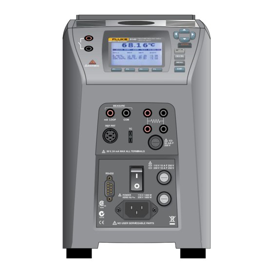
914X Field Metrology Wells Parts and Controls Figure 2 914X Field Metrology Well Parts and Controls This section describes the exterior features of the Field Metrology Well. All interface and power connections are found on the front of the instrument (see Figure 2). -
Page 25: Display Panel
Quick Start Parts and Controls 3.2.1 Display Panel Figure 3 on next page shows the layout of the display panel. Display (1) The display is a 240 x 160 pixel monochrome graphics LCD device with a bright LED back- light. The display is used to show current control temperature, measurements, status informa- tion, operating parameters, and soft key functions. -
Page 26: Display
914X Field Metrology Wells Parts and Controls Block Temperature Indicator (10) [Patent Pending] The Block Temperature Indicator lamp allows users to know when the block temperature is safe (50°C to 60°C) to remove inserts or move the Field Metrology Well. The indicator light is lit continuously once the block has exceeded approximately 50°C (varies 50°C to 60°C). -
Page 27: Figure 4 914X Display
Quick Start Parts and Controls Stability Status (4) On the right hand side of the screen, you will find a graph displaying the current status of the stability of the Field Metrology Well. Heating/Cooling Status (5) Just below the stability graph there is a bar graph that will indicate HEATING, COOLING, or CUTOUT. -
Page 28: Power Panel
914X Field Metrology Wells Parts and Controls 3.2.3 Power Panel The following are found on the lower front panel of the instrument (see Figures 5 and Figure 6 on opposite page). Power Cord Plug (1) The power supply cord attaches to the lower front power panel. Plug the cord into an AC mains supply appropriate for the voltage range as specified in the specifications tables. -
Page 29: Figure 5 9142 Power Panel
Quick Start Parts and Controls Figure 5 9142 power panel Figure 6 9143 and 9144 power panel... -
Page 30: P Option Panel (-P Models Only)
914X Field Metrology Wells Parts and Controls 3.2.4 -P Option Panel (-P models only) The –P (process version) panel is the readout portion of the instrument and is only available with –P models. MEASURE mA LOOP REF PRT 50 mA F 250 V 30 V, 24 mA MAX ALL TERMINALS Figure 7 -P option panel... -
Page 31: Figure 8 Probe Connector Wiring
Quick Start Parts and Controls Probe Connector Shield RTD Sensor Figure 8 Probe connector wiring A two-wire probe can also be used with the reference thermometer. It is connected by attach- ing one wire to both pins 1 and 2 of the plug and the other wire to both pins 4 and 5. If a shield wire is present, it should be connected to pin 3. -
Page 32: Languages
914X Field Metrology Wells Languages Figure 9 Jumper locations for 3-wire and 2-wire connections Thermocouple (TC) Connector (4) The TC connector allows for the use of subminiature TC connectors (see CE Comments on page 8 for information on using clamp-on ferrites). Fuse (5) Fuse for the 4-20 mA circuit. -
Page 33: Reset To English Language
Quick Start Languages Figure 10 Steps to language selection 3.3.2 Reset to English Language If you are in a language and need a short cut exit, press F1 and F4 simultaneously to reset the display to English. To reset to your originally selected language after resetting to English, follow the steps in Figure 10 on this page. -
Page 35: Menu Structure
Menu Structure Temp Setup Menu Menu Structure Temp Setup Menu 9142/9143/9144 MAIN MENU TEMP SETUP PROG MENU SYSTEM MENU INPUT SETUP (-P only) SETUP SCAN RATE: <edit> Degrees per minute at which the Field Metrology Well increases or decreases temperature STABLE LIMIT: <edit>... -
Page 36: Prog Menu
914X Field Metrology Wells Prog Menu Prog Menu 9142/9143/9144 MAIN MENU TEMP SETUP PROG MENU SYSTEM MENU INPUT SETUP (-P only) RUN PROGram TEST STATUS: <OFF, RUN> <select> Changes status of current test RUN TEST: <RAMP/SOAK, SWITCH TEST> <select> Runs selected test RECORD DATA: <YES, NO>... -
Page 37: Switch Test Parameters
Menu Structure Prog Menu 4.2.1 Switch Test Parameters SWITCH TEMP The SWITCH TEMP parameter is the nominal change temperature of the switch. UPPER TEMP The UPPER TEMP parameter is the temperature during a cycle at which the Field Metrology Well begins to heat or cool at the rate specified in “Scan Rate” found in MAIN MENU|TEMP SETUP|SETUP|SCAN RATE. -
Page 38: Figure 13 Auto And Manual Switch Test Operation Example
914X Field Metrology Wells Prog Menu RUN. Press Enter and the instrument will engage and start the test within a few seconds. Exit to the main screen to view the test progress, refer to the Menu Structure. When the switch resets, the test completes and the values of the switch OPEN, switch CLOSE, and switch BAND are displayed for the user to record. -
Page 39: System Menu
Menu Structure System Menu System Menu 9142/9143/9144 MAIN MENU TEMP SETUP PROG MENU SYSTEM MENU INPUT SETUP (-P only) SYSTEM SETUP DISPLaY SETUP LANGUAGE: <English, Japanese, Chinese, German, Spanish, French, Russian, Italian> <select> DECIMAL: <PERIOD, COMMA> <select> KEY AUDIO: <ON, OFF> <select> COMMunication SETUP BAUD RATE: <1200, 2400, 4800, 9600, 19200, 38400>... -
Page 40: Input Setup (-P Only)
914X Field Metrology Wells Input Setup (-P only) Input Setup (-P only) 9142/9143/9144 MAIN MENU TEMP SETUP PROG MENU SYSTEM MENU INPUT SETUP (-P only) SELECT INPUT SENSOR TYPE: <RTD, TC, mA> <select> SETUP INPUT RTD SETUP WIRES: <4, 2, 3> <select> RTD TYPE: <RESISTANCE, PT100(385), PT100(3926), PT100(JIS), NI-120>... - Page 41 Before using any cleaning or decontamination method, other than those recommended by ● Fluke’s Hart Scientific Division, users should check with an Authorized Service Center to insure the proposed method will not damage the equipment. If the instrument is used in a manner not in accordance with the equipment design, the ●...
- Page 42 914X Field Metrology Wells Field Metrology Well Performance Analysis Accuracy Drift The display temperature of the instrument will drift over time. This is due to a variety of factors affecting the temperature control PRT. Any PRT is subject to changes depending on how it is used and the environment it is used in.
Need help?
Do you have a question about the 914 Series and is the answer not in the manual?
Questions and answers