
Related Manuals for Fluke Dry-Well 9103


Summary of Contents for Fluke Dry-Well 9103
- Page 1 9103 Dry-Well User’s Guide 2005 Rev. 1, 9/21 © 2005-2021 Fluke Corporation. All rights reserved. Specifications are subject to change without notice. All product names are trademarks of their respective companies.
- Page 2 Fluke authorized resellers shall extend this warranty on new and unused products to end-user customers only but have no authority to extend a greater or different warranty on behalf of Fluke. Warranty support is available only if product is purchased through a Fluke authorized sales outlet or Buyer has paid the applicable international price.
-
Page 3: Table Of Contents
Table of Contents Title Page Introduction......................Contact Fluke Calibration ..................Safety Information ....................Service Information....................Specifications and Environmental Conditions ............. Specifications ....................Environmental Conditions................Quick Start......................Unpacking..................... Setup ......................Power ......................Set the Temperature.................... Parts and Controls ....................Rear Panel.................... - Page 4 9103 User’s Guide Temperature Scale Units................14 Secondary Menu ................... 14 Thermal Electric Devices (TED) ..............14 Proportional Band..................15 Controller Configuration ................16 Operating Parameters ................... 16 Serial Interface Parameters................16 BAUD Rate..................... 16 Sample Period..................17 Duplex Mode ....................17 Linefeed....................
-
Page 5: Introduction
Introduction The Fluke Calibration 9103 Dry-Well (the Product or the Calibrator) is a small portable instrument for quick on-site checks and calibration of thermocouple and RTD temperature probes. The Product is small enough to use in the field, and accurate enough to use in the lab. Calibrations can be done from -25 °... -
Page 6: Contact Fluke Calibration
Service Information Contact an authorized Fluke Calibration Service Center if the Product needs calibration or repair during the warranty period. Please have Product information such as the purchase date and serial number ready when you schedule a repair. -
Page 7: Specifications And Environmental Conditions
Dry-Well Specifications and Environmental Conditions Specifications and Environmental Conditions Specifications Specifications are in Table 1. Table 1. Specifications Range -25 °C to 140 °C (-13 °F to 284 °F), at 23 °C ambient Accuracy ±0.25 °C (±1.0°C in holes >6.4 mm (1/4 in)) ±0.02 °C at –25 °C Stability ±0.04 °C at 140 °C... -
Page 8: Environmental Conditions
9103 User’s Guide Environmental Conditions Although the Product has been designed for optimum durability and trouble-free operation, handle the Product with care. Caution To avoid damaging the Product: • Do not operate the Product in an excessively dusty or dirty environment. •... -
Page 9: Set The Temperature
3. Install the correct fuse: • 115 V or 250 V Fluke part number 109199. Fuse, 0.25x31.75 mm, 3 A, 250 V, fast blow. 4. Once installed, put the fuse holder back into the PEM. Make sure that the correct voltage shows on the closed fuse cover. -
Page 10: Thermal Electric Devices (Ted)
Power is controlled by periodically switching the TEDs on for a certain amount of time using power transistors. Figure 1. Back Panel RS-232 POWER 115/230 VAC, 50/60 Hz, 250 VA F 3 A, 250 V FLUKE CALIBRATION 6920 SEAWAY BLVD, M/S 143F EVERETT, WA 98203 www.flukecal.com ASSEMBLED IN USA... -
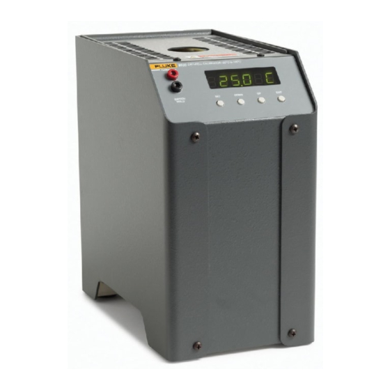
Page 11: Front Panel
Dry-Well Parts and Controls Front Panel Caution Always leave enough clearance in front of the calibrator to allow for safe and easy installation and removal of probes. Figure 2. Front Panel 9103 DRY-WELL CALIBRATOR –25°C to 140°C 910 3 DR Y-WELL CALIBRATOR –25°C to 140°C 104.6 C Smoked Display Window SWITCH... -
Page 12: Constant Temperature Block Assembly
9103 User’s Guide Constant Temperature Block Assembly The Block is made of aluminum and provides a relatively constant and accurate temperature environment. Insert the sensor to be calibrated inside the block. The 1.25 in diameter well is used for sensors of that size or can be sleeved down with various sized multi-hole probe sleeves. TEDs surround the block assembly and provide even heat to the sensor. -
Page 13: General
Dry-Well General General Change the Display Units The temperature units are factory defaulted to Celsius. To change to Fahrenheit or back to Celsius: 1. Push SET and UP simultaneously. The temperature display changes units. 1. Push SET three times from the temperature display to show Un= C 2. - Page 14 9103 User’s Guide Figure 4. Operational Flowchart Display Hold Temperature Display Temperature DOWN DOWN Select Setpoint Displays Set-Point Resistance Adjust Setpoint Toggles °C / °F EXIT EXIT Units °C/°F Secondary Functions EXIT Scan On/Off Menu EXIT Display Power Scan Rate Set Proportional Band Adj.
-
Page 15: Programmable Set-Points
Dry-Well Controller Operation Programmable Set-points The controller stores 8 set-point temperatures in memory. The set-points can be quickly recalled to conveniently set the Product to a previously-programmed temperature set-point. To set the temperature, first select the set-point memory. Push SET from the temperature display function to access this function. -
Page 16: Scan
9103 User’s Guide Scan Set and enable the scan rate so that when the set-point is changed the calibrator heats or cools at a specified rate (degrees per minute) until it reaches the new set-point. With the scan disabled, the calibrator heats or cools at the maximum possible rate. -
Page 17: Enable The Hold Temperature Display
Dry-Well Controller Operation Enable the Hold Temperature Display Push UP when the temperature shows to enable the Hold Temperature Display feature. The Hold Temperature Display shows the hold temperature on the right and the switch status on the left. The status c means the switch is closed and o means the switch is open. -
Page 18: Set-Point Resistance
9103 User’s Guide To set up the test: 1. Connect the switch wires to the terminals on the front of the Product and place the switch in the well. 2. Enable set-point scanning by setting the scan to ON in the primary menu (see Scan Control). -
Page 19: Proportional Band
Dry-Well Controller Operation Proportional Band In a proportional controller such as this, the heater output power is proportional to the well temperature over a limited range of temperatures around the set-point. This range of temperature is called the proportional band. At the bottom of the proportional band, the heater output is 100 %. At the top of the proportional band, the heater output is 0. -
Page 20: Controller Configuration
9103 User’s Guide Controller Configuration The Product has a number of configuration and operating options and calibration parameters which are programmable from the front panel. These are accessed from the secondary menu after the proportional band function by pushing SET. push SET again to enter the first of three sets of configuration parameters —... -
Page 21: Sample Period
Dry-Well Controller Operation Sample Period The next parameter in the serial interface parameter menu is the sample period. The sample period is the time period in seconds between temperature measurements transmitted from the serial interface. If the sample rate is set to 5, the Product transmits the current measurement over the serial interface approximately every 5 seconds. -
Page 22: Calibration Parameters
9103 User’s Guide Calibration Parameters The operator of the Product controller has access to a number of the calibration constants: R0, ALPHA, DELTA, and BETA. These values are set at the factory and must not be altered. The correct values are important to the accuracy and proper and safe operation of the Product. -
Page 23: Serial Communications
Dry-Well Digital Communication Interface Serial Communications The Product is installed with an RS-232 serial interface that allows serial digital communications over fairly long distances. With the serial interface the user can access any of the functions, parameters and settings discussed in Controller Operation with the exception of the BAUD rate setting. -
Page 24: Setup
9103 User’s Guide Setup Before operation the serial interface must first be set up by programming the BAUD rate and other configuration parameters. These parameters are programmed within the serial interface menu. The serial interface parameters menu is outlined in Figure 4. To enter the serial parameter programming mode: 1. -
Page 25: Serial Operation
Dry-Well Digital Communication Interface Serial Operation Once the cable has been attached and the interface set up properly the controller immediately begins transmitting temperature readings at the programmed rate. The serial communications uses 8 data bits, one stop bit, and no parity. The set-point and other commands can be sent with the serial interface to set the temperature set-point and view or program the various parameters. - Page 26 9103 User’s Guide Command Command Returned Acceptable Command Description Returned Format Example Example Values Configuration Menu Operating Parameters Menu Read High Limit hl: 999 hl: 140 Set High Limit hl=n hl=90 0-140 Serial Interface Menu Read serial sample setting sa[mple] sa: 9 sa: 1 Set serial sampling setting to n seconds...
-
Page 27: Test Probe Calibration
Dry-Well Test Probe Calibration Test Probe Calibration For optimum accuracy and stability, allow the Product to warm up for 25 minutes after power-up and then allow adequate stabilization time after reaching the set-point temperature. After completing operation of the calibrator, allow the well to cool by setting the temperature to 25 °C for one-half hour before turning off the power. -
Page 28: Calibration And Adjustment Procedure
9103 User’s Guide Calibration and Adjustment Procedure Sometimes the user may want to calibrate the Product to improve the temperature set-point accuracy. Calibration is done by adjusting the controller probe calibration constants R0, ALPHA, DELTA, and BETA so that the temperature of the calibrator as measured with a standard thermometer agrees more closely with the set-point. -
Page 29: Compute Delta
Dry-Well Calibration and Adjustment Procedure Compute DELTA − − − − − − E = R – R F = R – R delta DE CF - Measured temperature using the reference thermometer. - Value of R display. (Push SET and DOWN at the same time.) where and R are the measured temperature and resistance at -25 °C... -
Page 30: Compute R0 And Alpha
9103 User’s Guide Compute R0 and ALPHA delta − delta − rzero − alpha − delta is the new value of DELTA computed above. Compute BETA − delta rzero beta − − )( ) )( ) alpha x y alpha x y Where T and R are the measured temperature and resistance at –25.00 °C and alpha, rzero, and... -
Page 31: Accuracy And Repeatability
Contact Fluke Calibration) for more information. • Before using any cleaning or decontamination method except those recommended by Fluke Calibration, users should check with an Authorized Service Center to be sure that the proposed method will not damage the equipment. -
Page 32: Troubleshooting Problems, Possible Causes, And Solutions
If the problem cannot otherwise be solved, contact an Authorized Service Center (see Contact Fluke Calibration assistance. Be sure to have the model number, serial number, voltage, and problem description available. - Page 33 Perform the Factory Reset Sequence described and flashes err 6 above. If this does not fix the problem, contact Fluke Calibration. SenSor Heater control error. Perform the Factory Reset Sequence as described above to initialize the Product. If the Product repeats the error code, turn The display shows the Product off and allow the unit to sit at least one-half hour.
- Page 34 9103 User’s Guide...
Need help?
Do you have a question about the Dry-Well 9103 and is the answer not in the manual?
Questions and answers