Table of Contents
Advertisement
This .pdf document is bookmarked
Operating Instructions and Parts Manual
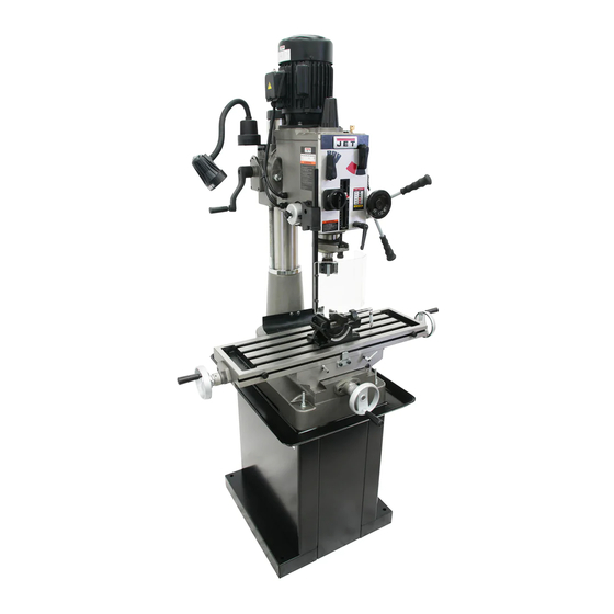
Geared Head Mill-Drill Machines
Models: JMD-40GH, JMD-40GHPF, JMD-45GH, JMD-45GHPF
JMD-40GH
JMD-45GHPF
JET
427 New Sanford Road
LaVergne, Tennessee 37086
Part No. M-351040
Ph.: 800-274-6848
Edition 1 03/2017
www.jettools.com
Copyright © 2017 JET
1
Advertisement
Table of Contents


Need help?
Do you have a question about the JMD-40GHPF and is the answer not in the manual?
Questions and answers