Jet J-2221VS Operating Instructions And Parts Manual
20-inch variable speed drill presses
Hide thumbs
Also See for J-2221VS:
- Operating instructions and parts manual (32 pages) ,
- Operating instructions and parts manual (28 pages)
Table of Contents
Advertisement
This .pdf document is bookmarked
Operating Instructions and Parts Manual
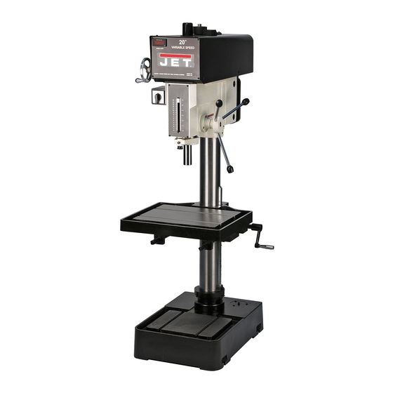
20-inch Variable Speed Drill Presses
Models: J-2221VS, J-2223VS, J-2232AC, J-2234AC
WALTER MEIER (Manufacturing) Inc.
427 New Sanford Road
LaVergne, Tennessee 37086
Part No. M-354221
Ph.: 800-274-6848
Revision B3 04/2012
www.waltermeier.com
Copyright © 2012 Walter Meier (Manufacturing) Inc.
Advertisement
Table of Contents

Related Manuals for Jet J-2221VS


Summary of Contents for Jet J-2221VS
- Page 1 This .pdf document is bookmarked Operating Instructions and Parts Manual 20-inch Variable Speed Drill Presses Models: J-2221VS, J-2223VS, J-2232AC, J-2234AC WALTER MEIER (Manufacturing) Inc. 427 New Sanford Road LaVergne, Tennessee 37086 Part No. M-354221 Ph.: 800-274-6848 Revision B3 04/2012 www.waltermeier.com...
-
Page 2: Warranty And Service
Walter Meier is consistently adding new products to the line. For complete, up-to-date product information, check with your local Walter Meier distributor, or visit waltermeier.com. WARRANTY JET products carry a limited warranty which varies in duration based upon the product (MW = Metalworking, WW = Woodworking). WHAT IS COVERED? This warranty covers any defects in workmanship or materials subject to the exceptions stated below. -
Page 3: Table Of Contents
Replacement Parts ........................... 16 Drill Head – Manual Speed Control (J-2221VS and J-2223VS) ............17 Parts List: Drill Head – Manual Speed Control (J-2221VS and J-2223VS) ........18 Drill Head – Inverter Speed Control (J-2232AC and J-2234AC) ............20 Parts List: Drill Head – Inverter Speed Control (J-2232AC and J-2234AC) ........21 Spindle Components (All Models) .................... -
Page 4: Warning
- Always be sure the machine support is results and full benefits from your machine. securely anchored to the floor or the work Used properly, JET machinery is among the bench. best in design and safety. However, any machine used improperly can be rendered When using machine: inefficient and unsafe. -
Page 5: General Electrical Cautions
12. Never brush away chips while the machine 17. Keep hands in sight and clear of all moving is in operation. parts and cutting surfaces. 13. Keep work area clean. Cluttered areas invite 18. All visitors should be kept at a safe distance accidents. -
Page 6: Safety Instructions For Drill Presses
Introduction This manual is provided by Walter Meier (Manufacturing) Inc., covering the safe operation and maintenance procedures for a JET 20-inch Variable Speed Drill Press. This manual contains instructions on installation, safety precautions, general operating procedures, maintenance instructions and parts breakdown. -
Page 7: General Specifications
General Specifications The JET 20-inch Variable Speed Drill presses Models J-2221VS, J-2223VS, J-2232AC and J-2234AC are available in manual speed control or inverter speed control configuration. Electrical power options are single-phase, 115 and 220 volts; or 3-phase, 440 volts. Manual Speed Control Models Inverter Speed Control Models Model ............ -
Page 8: Operation And Set-Up
The JET Model J-2221VS and J-2223VS drill Operation and Set-Up presses feature manual speed control. Models J-2232AC and J-2234AC have inverter speed Securing the Base control. This manual contains procedures for both speed control versions. The manual The base of the drill press has four mounting provides separate instructions when differences slots;... -
Page 9: Raising The Drill Head And Table
3. If your incoming power is three phase, connect the three leads to L1, L2 and L3, NOTE: If rewiring the J-2221VS or J-2223VS for and the green ground wire to the grounding alternate voltage, you must reconnect the wire screw. -
Page 10: Operating Controls
Inverter Speed Control (Models J- Operating Controls 2232AC and J-2234AC) Speed Shift Lever Manual Speed Control (Models J- 2221VS and J-2223VS) To avoid damage to the Refer to Figure 4. speed adjustment mechanism, the drive motor must be operating before attempting Spindle Selector Switch to adjust the speed setting. -
Page 11: Depth Indicator - All Models
(clockwise increases). exposure to potentially lethal voltage levels. Spindle Selector The SPINDLE selector switch is used to set the Manual Speed Control (Models J-2221VS and desired direction of spindle rotation. The REV. J-2223VS) (reverse) setting will provide counterclockwise 1. -
Page 12: Replacement Of Motor
Following are lubrication recommendations for and connect electrical wiring (refer to Wiring drill press components. Diagram section for wiring details). Manual Speed Control (Models J-2221VS and 11. Install the head cover and secure with pan J-2223VS) screws and eight bolts. -
Page 13: Adjustments
The radial position of the drill head can be changed to accommodate the drilling of a hole that may be offset from the center of the table. Reposition the drill head as follows: 1. Loosen the two clamping hex nuts using the hex socket wrench provided with the machine. -
Page 14: Drilling Recommendations
Indication of Extreme Speeds and Drilling Recommendations Feeds Speeds for Drilling A drill that splits up the web is evidence of too much feed or insufficient tip clearance at the The speed of a drill is usually measured in terms center as a result of improper grinding. -
Page 15: Optional Equipment
Optional Equipment 6. Install the 3/8-inch hose coupling to the Coolant System Installation coolant pump. If needed, apply a light coat of pipe sealant or Teflon tape to the threads 1. Remove the large reservoir cover plate from to prevent leakage. the machine base. -
Page 16: Replacement Parts
Troubleshooting Trouble Probable Cause Remedy Motor overload protector tripped. Press motor overload reset button. Circuit breaker tripped. Reset circuit breaker. Branch circuit breaker tripped or fuse Reset branch circuit breaker/replace fuse. blown. Spindle does not turn. Open wire in switch circuit. Repair open circuit. -
Page 17: Drill Head - Manual Speed Control (J-2221Vs And J-2223Vs)
Drill Head – Manual Speed Control (J-2221VS and J-2223VS) -
Page 18: Parts List: Drill Head - Manual Speed Control (J-2221Vs And J-2223Vs)
Parts List: Drill Head – Manual Speed Control (J-2221VS and J-2223VS) Index No. Part No. Description Size 7 ....5510077 ....Spindle Step Pulley ................1 8 ....5510078 ....Spindle Nut ..................1 9 ....5510079 ....V-Belt....................1 10 .... 5510080 ....VS Lower Spindle Pulley ..............1 11 .... - Page 19 Index No. Part No. Description Size 60B..J-5513680 ....Cover Plate ..................1 60C ..5513681 ....Cap Screw ..................2 60D ..J-5513682 ....Plate Bracket ..................1 61 .... 5510131 ....Thrust Bearing ..................1 62 .... 5510132 ....Shaft ....................1 63A..5513683 ....Cap Screw ..................2 64A..
-
Page 20: Drill Head - Inverter Speed Control (J-2232Ac And J-2234Ac)
Drill Head – Inverter Speed Control (J-2232AC and J-2234AC) 67-4 84-1 84-2 67-6 85-1 85-2 64-1 74-1 49-1 75-1 51-1 51-2 86-1 44-1 40-1 89-1 26-1... -
Page 21: Parts List: Drill Head - Inverter Speed Control (J-2232Ac And J-2234Ac)
Parts List: Drill Head – Inverter Speed Control (J-2232AC and J-2234AC) Index No. Part No. Description Size 1 ....J-5517332....Head Casting ......................1 2 ....5510142....... Oil Window ......................1 3 ....5510143....... Ball Bearing ......................1 4 ....5510144....... Retaining Ring.......................1 5 ....5510145....... - Page 22 Index No. Part No. Description Size 56-2.....5510198....... Proximity Switch Bracket..................1 57 ....5510201....... Indicator Light......................1 59 ....5510199....... Pump Selector Switch ...................1 60 ....5510200....... Forward/Reverse Switch ..................1 61 ....5510196....... Speed Control Potentiometer ................1 62 ....5510202....... Green Pushbutton Switch ..................1 63 ....5510206.......
-
Page 23: Spindle Components (All Models)
Spindle Components (All Models) To Head Parts List: Spindle Components (All Models) Index No. Part No. Description Size 1 ....J-5517332 ....Head Casting ..................1 2 ....5517376 ....Hex Shoulder Bolt ................2 2-1 ... 5517377 ....Spring ....................2 3 ....5517378 ....Cam Lock Rod..................2 4 .... - Page 24 Index No. Part No. Description Size 26 .... 5510261 ....Socket Head Screw ................1 27 .... 5510262 ....Washer ....................1 28 .... 5510263 ....Container (includes #29) ..............1 29 .... 5510263 ....Return Spring ..................1 30 .... 5510265 ....Socket Head Screw ................3 31 ....
-
Page 25: Table And Base (All Models)
Table and Base (All Models) 35-1 35-2 35-3 37-1 32A 31 18-1 18-2 18-3 40-1 Line in 37-1 To Pump 62 44... -
Page 26: Parts List: Table And Base (All Models)
Parts List: Table and Base (All Models) Index No. Part No. Description Size 1 ....J-5510288 ....Base ....................1 ....J-5510288A .....Base ......... 1 (serial no. 7090589 and higher for 2221/2223VS (serial no. 7100425 and higher for 2232/2234AC) 1-1 ... TS-0720111 ....Lock Washer ............1/2" ......6 1-2 ... - Page 27 Index No. Part No. Description Size 36 .... J-5510321 ....Table Raise Crank ................2 37 .... J-5510322 ....Table ....................1 37-1 ..5517399 ....Hose Coupler (Return) ........1/2" ......1 38 .... 5510323 ....Column ....................1 ....5510323A....Column ......1 (serial no. 7090589 and higher for 2221/2223VS (serial no.
-
Page 28: Wiring Diagram - Models J-2221Vs And J-2223Vs
Wiring Diagram – Models J-2221VS and J-2223VS... -
Page 29: Wiring Diagram - Models J-2232Ac And J-2234Ac
Wiring Diagram – Models J-2232AC and J-2234AC... - Page 30 NOTES...
- Page 32 WALTER MEIER (Manufacturing) Inc. 427 New Sanford Road LaVergne, Tennessee 37086 Phone: 800-274-6848 www.waltermeier.com...
Need help?
Do you have a question about the J-2221VS and is the answer not in the manual?
Questions and answers