Table of Contents
Advertisement
This .pdf document is bookmarked
Operating Instructions and Parts Manual
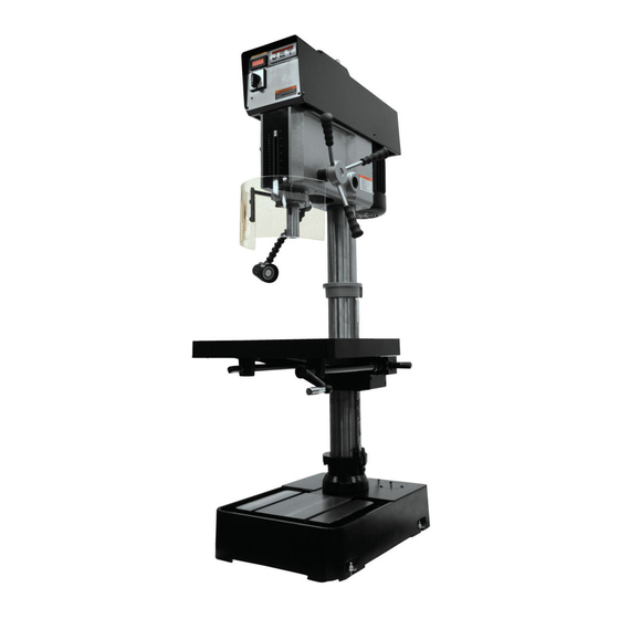
20" Variable Speed Drill Press
Models: JDP-20VS-1, JDP-20VS-3, JDP-20VST
JDP-20VST
JDP-20VS
JET
427 New Sanford Road
LaVergne, Tennessee 37086
Part No. M-354230
Ph.: 800-274-6848
Edition 5 10/2018
www.jettools.com
Copyright © 2017 JET
Advertisement
Table of Contents

Related Manuals for Jet JDP-20VS-3


Summary of Contents for Jet JDP-20VS-3
- Page 1 This .pdf document is bookmarked Operating Instructions and Parts Manual 20” Variable Speed Drill Press Models: JDP-20VS-1, JDP-20VS-3, JDP-20VST JDP-20VST JDP-20VS 427 New Sanford Road LaVergne, Tennessee 37086 Part No. M-354230 Ph.: 800-274-6848 Edition 5 10/2018 www.jettools.com Copyright © 2017 JET...
-
Page 2: Important Safety Instructions
- Always be sure the machine support is and full benefits from your machine. Used properly, securely anchored to the floor or the work JET machinery is among the best in design and bench. safety. However, any machine used improperly can be rendered inefficient and unsafe. -
Page 3: General Electrical Cautions
17. Keep hands in sight and clear of all moving wiring system; or to a system having an parts and cutting surfaces. equipment-grounding conductor. 18. All visitors should be kept at a safe distance WARNING: This product can expose you to from the work area. -
Page 4: Safety Instructions For Drill Presses
If there are questions or comments, please contact your local supplier or JET. JET can also be reached at our web site: www.jettools.com. -
Page 5: Table Of Contents
13.5.1 Table and Base Assembly (All Models) – Exploded View ..............25 13.5.2 Table and Base Assembly (All Models) – Parts List ................26 14.0 Electrical connections ..........................28 14.1 JDP-20VS-1 and JDP-20VS-3 wiring diagram ..................28 14.2 JDP20VST wiring diagram ........................29 15.0 Warranty and Service ..........................30... -
Page 6: Specifications For Jdp-20Vs Series Drill Press
4.0 Specifications for JDP-20VS series Drill Press Model number JDP-20VS-1 JDP-20VS-3 JDP-20VST Stock number 354230 354231 354240 Motor and Electricals Motor type TEFC induction Horsepower 2 HP (1.5kW) Phase Voltage 115/230 V 230/460 V 230 V only (prewired 115V) (prewired 230V) -
Page 7: Mounting Hole Centers (All Models)
= not applicable The above specifications were current at the time this manual was published, but because of our policy of continuous improvement, JET reserves the right to change specifications at any time and without prior notice, without incurring obligations. -
Page 8: Set-Up And Assembly
Loosen head locking nut (A, Figure 5-1) by Read and understand the entire turning counterclockwise with provided socket contents of this manual before attempting set- wrench. up or operation! Failure to comply may cause Grasp head and turn it slightly from side to side serious injury. -
Page 9: Electrical Connections
See sect. 6.3. Diagrams are also found at back of this manual. The JDP-20VS-3 is pre-wired for 3-phase, 230-volt. (If discrepancies should occur, diagrams on The machine can also be run on 460V power. See machine take precedence.) -
Page 10: Operating Controls
Adjustment knob (E ): Sets depth stop position. 7.0 Operating controls Lock knob (E ): Locks setting of depth stop. 7.1 JDP-20VS-1/3 controls Work light (F): Has separate on/off switch atop shade; flexible positioning. Refer to Figure 7-1. Speed range switch (G): Two ranges. Middle LED Display (A): Shows spindle RPM selected by position is neutral –... -
Page 11: Tool Installation And Removal
Set depth block to zero by turning knurled knob If installing a drill chuck, retract the jaws then ). Then adjust block to desired depth of hole, use rubber mallet (or steel face hammer against and secure setting with knob (E a block of wood) to sharply tap bottom of chuck two or three times to seat it. -
Page 12: Coolant Pump (Optional)
8.6 Coolant pump (optional) SFM = 0.26 X RPM X Drill Diameter (in inches) The coolant system (not provided) should be filled RPM = 3.8 x ________SFM__________ with 2 gallons of a cutting coolant. Fill by pouring Drill diameter (in inches) coolant into base of machine. -
Page 13: User-Maintenance
10.3 Lubrication 9.2.4 Excessive speed/feed indicators A drill that splits up the web is evidence of too much Table lubrication points feed or insufficient tip clearance at the center as a recommended frequency. Avoid getting oil or result of improper grinding. The rapid wearing away grease on belts. -
Page 14: Coolant System (Optional)
DO NOT mount components above the line shown in Figure 11- (optional) Coolant pump system is optional. Contact your JET Install power switch and valve bracket with the dealer for more information. See sect. 13.5.2 for provided fasteners. -
Page 15: Troubleshooting Jdp-20Vs Series Drill Press
Non-proprietary parts, such as fasteners, can be found at local hardware stores, or may be ordered from JET. Some parts are shown for reference only, and may not be available individually. -
Page 16: Drill Head - Manual Speed Control (Jdp-20Vs-1/3) - Exploded View
13.1.1 Drill Head – Manual Speed Control (JDP-20VS-1/3) – Exploded View... -
Page 17: Drill Head - Manual Speed Control (Jdp-20Vs-1/3) - Parts List
13.1.2 Drill Head – Manual Speed Control (JDP-20VS-1/3) – Parts List Index No. Part No. Description Size 1 ....5510126 ...... Hand Grip......................1 2 ....5510126 ...... Handwheel (includes #1) ..................1 3 ....JDP20VS-TH03... Bushing ........................ 1 4 .... - Page 18 ....JDP20VS-WL ....Work Light (not shown) ..........input 110V ...... 1 ....LM000265 ....ID/Warning Label, JDP-20VS-1 (not shown) ..........1 ....LM000266 ....ID/Warning Label, JDP-20VS-3 (not shown) ..........1 ....JET-113 ..... JET Logo (not shown) ..........113x47mm ....1...
-
Page 19: Drill Head - Two Speed Control (Jdp20Vst) - Exploded View
13.2.1 Drill Head – Two Speed Control (JDP20VST) – Exploded View... -
Page 20: Drill Head - Two Speed Control (Jdp20Vst) - Parts List
13.2.2 Drill Head – Two Speed Control (JDP20VST) – Parts List Index No. Part No. Description Size 1 ....5510126 ...... Hand Grip......................1 2 ....5510126 ...... Handwheel (includes #1) ..................1 3 ....JDP20VS-TH03... Bushing ........................ 1 4 .... - Page 21 120 ..... JDP20VST-H120 ..Power Indicator Light ..................1 121 ..... JDP20VS-WL ....Work Light ..............input 110V ...... 1 ....LM000267 ....ID/Warning Label, JDP-20VST (not shown) ..........1 ....JET-92 ....... JET Logo (not shown) ..........92x38mm ...... 1...
-
Page 22: Spindle Components (All Models) - Exploded View
13.3.1 Spindle Components (All Models) – Exploded View... -
Page 23: Spindle Components (All Models) - Parts List
13.3.2 Spindle Components (All Models) – Parts List Index No. Part No. Description Size 1 ....JDP20VS-HD .... Head Body for JDP20VS series ..............1 2 ....5510320 ....Rear Cam Lock ....................2 3 ....5510250 ....Hex Nut ......................1 4 .... -
Page 24: Safety Shield Assembly (All Models) - Exploded View
13.4.1 Safety Shield Assembly (All Models) – Exploded View 13.4.2 Safety Shield Assembly (All Models) – Parts List Index No. Part No. Description Size ....32106A ..... Safety Shield Assembly (#1 thru 16) ............1 1 ....6293347 ....Spring Pin............. 3x16 ......1 2 .... -
Page 25: Table And Base Assembly (All Models) – Exploded View
13.5.1 Table and Base Assembly (All Models) – Exploded View... - Page 26 13.5.2 Table and Base Assembly (All Models) – Parts List Index No. Part No. Description Size 1 ....J-5510288A ....Base....................... 1 1-1 ..... TS-0720111 ....Lock Washer ............1/2" ........ 6 1-2 ..... TS-0070031 ....Hex Cap Screw ............1/2" x 1-1/2” ....6 2 ....
- Page 27 Index No. Part No. Description Size 49 ....5517400 ....Pan Head Screw .................... 1 50 ....5517401 ....Clear Vinyl Hose ............1/2" ........ 1 51 ....5517402 ....Hose Clamp ....................1 53 ....5517404 ....Drain Plug ..............3/8 NPT ......1 55 ....
-
Page 28: Electrical Connections
14.0 Electrical connections Similar diagrams are affixed inside electrical cabinet door. In case of discrepancy, diagrams on machine take precedence. 14.1 JDP-20VS-1 and JDP-20VS-3 wiring diagram... -
Page 29: Jdp20Vst Wiring Diagram
14.2 JDP20VST wiring diagram... -
Page 30: Warranty And Service
JET sells through distributors only. The specifications listed in JET printed materials and on official JET website are given as general information and are not binding. JET reserves the right to effect at any time, without prior notice, those alterations to parts, fittings, and accessory equipment which they may deem necessary for any reason ®... - Page 31 This page intentionally left blank.
- Page 32 427 New Sanford Road LaVergne, Tennessee 37086 Phone: 800-274-6848 www.jettools.com...
Need help?
Do you have a question about the JDP-20VS-3 and is the answer not in the manual?
Questions and answers