Table of Contents
Advertisement
Available languages
Available languages
Advertisement
Chapters
Table of Contents

Related Manuals for Jet J-2500


Summary of Contents for Jet J-2500
-
Page 1: Drill Press
This .pdf document is bookmarked Operating Instructions and Parts Manual Drill Press Models: J-2500, J-2530, J-2550 J-2530 J-2500 J-2550 427 New Sanford Road LaVergne, Tennessee 37086 Part No. M-354400 Ph.: 800-274-6848 Revision C3 01/2017 www.jettools.com Copyright © 2017 JET... -
Page 2: Warranty And Service
Accessories; Shop Tools; Warehouse & Dock products; Hand Tools; Air Tools NOTE: JET is a division of JPW Industries, Inc. References in this document to JET also apply to JPW Industries, Inc., or any of its successors in interest to the JET brand. -
Page 3: Table Of Contents
J-2550 – 230V ..............................25 The specifications in this manual are given as general information and are not binding. JET reserves the right to effect, at any time and without prior notice, changes or alterations to parts, fittings, and accessory equipment... -
Page 4: Warnings
5. Do not use this drill press for other than its intended use. If used for other purposes, JET disclaims any real or implied warranty and holds itself harmless from any injury that may result from that use. - Page 5 26. Use recommended accessories; improper accessories may be hazardous. 27. Maintain tools with care. Keep drill bits sharp and clean for the best and safest performance. Follow instructions for lubricating and changing accessories. 28. Make sure the work piece is securely attached or clamped to the table. Never use your hand to hold the work piece.
-
Page 6: Introduction
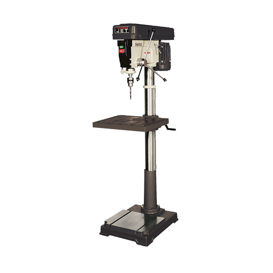
Introduction The JET 15-Inch 16-Speed Drill Presses and 20-Inch 12-Speed Drill Presses, Models J-2500, J-2530 and J-2550, feature rugged cast iron design with ground-steel columns for drilling accuracy in metal, wood, and plastic. The head casting features a ball bearing spindle assembly, supported by four permanently-lubricated, heavy duty ball bearings that are mounted in an enclosed quill for extended life. -
Page 7: Shipping Contents
Shipping Contents Unpack the carton and verify that all parts listed below are included. Other Material Main Parts 1 ea Owner’s Manual 1 ea Head Assembly 1 ea Warranty Registration Card 1 ea Table 1 set Column and Table Bracket Assembly 1 ea Base Required Tools... -
Page 8: Assembly
2. Compare the contents of the shipping container with the list found above. Report any shortages or damage to your JET distributor. 3. Clean all rust protected surfaces with kerosene Figure 2 or a light solvent. Do not use lacquer thinner, paint thinner, or gasoline. -
Page 9: Column Lock Handle
3. Tighten two setscrews (A) with a 5mm hex Column Lock Handle wrench (provided) until they are snug. Referring to Figure 5: Thread the column lock handle (D) into the table bracket (E). Figure 7 4. Install three downfeed handles (B) into the downfeed hub (C). -
Page 10: Chuck And Arbor Removal
Adjustment Chuck and Arbor Removal Depth Stop Adjustment Referring to Figure 9: Referring to Figure 10: 1. Unplug machine from the power source. To drill multiple holes at the same preset depth, use 2. Raise the table until it is about seven inches the depth stop: below the chuck. -
Page 11: Changing Spindle Speeds
4. For desired speed, change the location of belts per pulley/belt arrangement chart. Figure 11 5. Rotate the tension adjuster (F. Fig. 11) counterclockwise to tension the belts. Figure 12 – Spindle Speed Chart for J-2500, J-2530 Figure 13 – Spindle Speed Chart for J-2550... -
Page 12: Return Spring Adjustment
Operation Figure 14 Installing Drills Work Light (J-2500 and J-2530 only) Insert the drill into the chuck jaws about 1" (25.4mm) long. When using a small drill do not insert it so far Install a light bulb, no larger than 60 watts into the that the jaws touch the flutes of the drill. -
Page 13: Maintenance
Electrical Disconnect the machine from the power source. Grounding Instructions The JET drill press motor has four numbered leads that are factory connected for 115V operation, as shown in (A). For 230V operation reconnect the leads as shown in (B). -
Page 14: Extension Cords
draw. An undersized cord will cause a drop in the line voltage resulting in power loss and overheating. The table following shows the correct size to use depending on the cord length and nameplate ampere rating. If in doubt, use the next heavier gauge. Remember, the smaller the gauge number, the heavier the cord. -
Page 15: Troubleshooting
Troubleshooting Trouble Probable Cause Remedy Drill press unplugged from wall, or motor. Check all plug connections. Fuse blown, or circuit breaker tripped. Replace fuse, or reset circuit breaker. Drill press will not start. Cord damaged. Replace cord. Starting capacitor bad. Replace starting capacitor. -
Page 16: Replacement Parts
CST. Having the Model Number and Serial Number of your machine available when you call will allow us to serve you quickly and accurately. Non-proprietary parts, such as fasteners, can be found at local hardware stores, or may be ordered from JET. Some parts are shown for reference only, and may not be available individually. - Page 17 ....JDP15-1038 ..... Feed Shaft Assy (includes #37 thru #39) ..........1 39 ..... JDP12-55 ....Roll Pin ..............M5x16 ......1 43A... J-2500-43A ....Handle Bar Assembly ................1 45 ..... 10604505 ....Scale Ring ....................1 50A... JDP15-1050 ..... Spring Cap ....................1 51 .....
- Page 18 162 ... 10916202 ....Warning Label ................... 1 166 ... JDP15-1166 ..... Speed Diagram ..................1 169 ... JET-92 ..... JET Logo Plaque ..........92x38mm ..... 1 170 ... 2658MZDU36 ..Drive Screw ............Φ 2.3-5 ......6 601 ... TS-2245082 ..... Cr. Re. Pan Head Screw ........M5-8 ......4 602 ...
-
Page 19: Exploded View - J-2500, J-2530
Exploded View – J-2500, J-2530... -
Page 20: Parts List - J-2550
Parts List – J-2550 Index No. Part No. Description Size 1 ....J-5627751 ....Base......................1 2 ....J-5627761 ....Collar, Column ................... 1 3 ....5626231 ....Set Screw .............M10 x 40 mm ....1 4 ....5627771 ....Column ...................... 1 5 .... - Page 21 149 ... 5629461 ....Pin, Roll ..................... 2 166 ... 11316501 ....Speed Diagram ..................1 169 ... JET-113 ....JET Logo Plaque ..........113x47mm ....1 601 ... 5629471 ....Screw, Pan Head ..........M4 x 12 mm ....1 602 ... 5629481 ....Washer, External Tooth Lock .......Ø4 ........ 2 605 ...
- Page 22 Parts List – J-2550 Index No. Part No. Description Size 610 ... 5513738 ....Screw ......................2 611 ... 5513739 ....Block, Depth Stop ..................1 612 ... 5513740 ....Nut ......................1 613 ... 5513741 ....Rod, Depth Stop Adjustment ........2550 Only ....1 614 ...
-
Page 23: Exploded View - J-2550
Exploded View – J-2550... -
Page 24: Wiring Diagram
Wiring Diagram J-2500/J-2530 – 115V J-2500/J-2530 – 230V... -
Page 25: 115V
J-2550 – 115V J-2550 – 230V... - Page 26 This page intentionally left blank.
- Page 27 This page intentionally left blank.
- Page 28 427 New Sanford Road LaVergne, Tennessee 37086 Phone: 800-274-6848 www.jettools.com...
- Page 29 Manual de instrucciones de operación y piezas Taladro de columna Modelos: J-2500, J-2530, J-2550 J-2530 J-2500 J-2550 427 New Sanford Road LaVergne, Tennessee 37086 Núm. de stock M-354400 Teléfono: 800-274-6848 Revisión C3 01/2017 www.jettools.com Copyright © 2017 JET...
-
Page 30: Garantía Y Servicio Técnico
1-800-274-6846, 8AM to 5PM CST, de lunes a viernes. Período de la Garantía La garantía general, dura el período especificado en el documentación que se incluye con el producto o en el oficial JET sitios web de marca. • Los JET productos tienen una garantía limitada, la cual varía en duración dependiendo del producto. (Ver tabla de abajo) •... -
Page 31: Índice De Materias
J-2550 – 230 V ..............................25 NOTAS ................................. 26 Las especificaciones en este manual se ofrecen como información general y no son vinculantes. JET se reserva el derecho de efectuar, en cualquier momento y sin previo aviso, aquellos cambios o alteraciones que considere... -
Page 32: Advertencias
5. No use este taladro de columna, para ningún uso que no sea aquél para el que está destinado. Si se utiliza para otros fines, JET niega cualquier garantía real o implícita y no se responsabiliza por ninguna lesión que pueda resultar de dicho uso. -
Page 33: Guarde Estas Instrucciones
25. Use la herramienta adecuada con la velocidad y la tasa de avance correctas. No trate de usar una herramienta o accesorio en una tarea para la que no fue diseñado. La herramienta adecuada hará el trabajo mejor y con menos riesgos. 26. -
Page 34: Introducción
Los taladros de columna de 16 velocidades y 15 pulg. Y los taladros de columna de 12 velocidades y 20 pulg., de JET Modelos J-2500, J-2530 y J-2550, tienen diseño sólido de hierro forjado con columnas de acero con rectificación para precisión del taladrado en metal, madera y plástico. El molde del cabezal tiene un conjunto de husillo con rodamiento de bolas, soportado por cuatro cojinetes de bola muy resistentes permanentemente lubricados montados en un eje hueco cubierto para vida útil prolongada. -
Page 35: Contenido Del Envío
Contenido del envío Desempaque la caja de cartón y verifique que estén incluidas todas las piezas listadas a continuación. Otros materiales Piezas principales 1 c/u Manual del propietario 1 c/u Conjunto del cabezal 1 c/u Tarjeta de registro de la garantía 1 c/u Mesa 1 juego Conjunto de columna y soporte de la mesa... -
Page 36: Ensamblaje
2. Compare el contenido de la caja de envío con la lista anterior. Reporte cualquier pieza faltante o daño a su distribuidor de JET. 3. Limpie todas las superficies protegidas contra la oxidación con keroseno o un solvente suave. No use diluyente de barniz o de pintura ni gasolina. -
Page 37: Manivela De Bloqueo De La Columna
1. Con ayuda otra persona, levante cuidadosamente el cabezal hasta la parte superior de la columna y deslícelo para instalarlo en su lugar ¡El conjunto del cabezal es pesado! ¡Tenga cuidado al levantarlo para instalarlo en la Figura 4 columna! 2. -
Page 38: Remoción Del Mandril Y El Árbol
Ajuste Ajuste del tope de profundidad Viendo la Figura 10: Para taladrar orificios múltiples la misma profundidad prefijada, use el tope de profundidad: 1. Marque con un lápiz la profundidad en que la broca taladrará la pieza de trabajo. 2. Con la broca en el mandril, baje el mango de avance descendente para hacer avanzar la broca hasta su marca (A). -
Page 39: Cambio De Las Velocidades Del Husillo
5. Dé vueltas al ajustador de tensión (F. Fig. 11) en sentido antihorario para tensar las bandas. Figura 12 – Tabla de velocidades del husillo para J-2500, J-2530 Figura 13 – Tabla de velocidades del husillo para J-2550... -
Page 40: Ajuste Del Resorte De Retorno
Las tuercas hexagonales se deben apretar contra cada una. Figura 15 Figura 14 Figura 16 Luz de trabajo (J-2500 y J-2530 Operación únicamente) Instale un foco de no más de 60 watts en el Instalación de los taladros tomacorriente desde la parte trasera del cabezal. -
Page 41: Operación Básica
Operación básica Elementos eléctricos Coloque el material que va a taladrar de manera Instrucciones de puesta a tierra que entre en contacto con el lado izquierdo de la columna. Esto evita que el material gire. Esta herramienta debe estar puesta a tierra mientras esté... -
Page 42: Operación En 230 Voltios
Desconecte la máquina de la fuente de alimentación. demasiado pequeño producirá una caída en el voltaje de línea produciendo una pérdida de El motor del taladro de columna de JET tiene cuatro potencia y el sobrecalentamiento . La siguiente tabla alambres de conexión numerados y conectados en muestra el tamaño correcto que se debe usar,... -
Page 43: Localización Y Reparación De Problemas
Localización y reparación de problemas Problema Causa probable Solución Taladro de columna desenchufado de la pared o Verificar todas las conexiones del enchufe. el motor. Se fundió un fusible o se disparó el interruptor El taladro de columna no Reemplazar fusible o reposicionar el interruptor de circuito. de circuito. -
Page 44: Piezas De Reemplazo
....10600404A1 .... Conjunto de la columna para J-2530 / JDP-15M (inc. #2A y #4A) ...... 1 ....10400401A1 .... Conjunto de la columna para J-2500 / JDP-15MF (inc. #2B, #3 y #4B) ....1 5 ....TS-2229403 ..... Perno de cabeza hexagonal .........M10x40 ......4 6 .... - Page 45 ....JDP15-1038 ..... Conjunto del eje de alimentación (inc. del #37 al #39) ......1 39 ..... JDP12-55 ....Clavija cilíndrica ............M5-16 ......1 43A... J-2500-43A ....Barra del mango ..................1 45 ..... 10604505 ....Aro de la escala ..................1 50A...
- Page 46 162 ... 10916202 ....Etiqueta de advertencia ................1 166 ... JDP15-1166 ..... Diagrama de velocidades ................1 169 ... JET-92 ..... JET logotipo de la placa ................1 170 ... 2658MZDU36 ..Clavo-tornillo ............Φ 2.3-5 ......6 601 ... TS-2245082 ..... Tornillo de cabeza troncocónica Cr. Re....M5-8 ......4 602 ...
-
Page 47: Vista Ampliada - J-2500, J-2530
Vista ampliada – J-2500, J-2530... -
Page 48: Lista De Piezas - J-2550
Lista de piezas – J-2550 Núm. de índice Núm. de pieza Descripción Tamaño Cant. 1 ....J-5627751 ....Base......................1 2 ....J-5627761 ....Abrazadera de columna ................1 3 ....5626231 ....Tornillo de fijación ..........M10 x 40 mm ....1 4 .... - Page 49 Lista de piezas – J-2550 Núm. de índice Núm. de pieza Descripción Tamaño Cant. 55 ..... 5627331 ....Tuerca hex ............M10 ......1 56 ..... 5629111 ....Eje hueco (Nota 1) ..................1 56A... 5629121 ....Ensamblaje del eje hueco ................. 1 57 .....
- Page 50 Tamaño Cant. 169 ... JET-113 ....JET logotipo de la placa ........113 x 47 mm ....1 601 ... 5629471 ....Tornillo de cabeza troncocónica ......M4 x 12 mm ....1 602 ... 5629481 ....Arandela de fijación del diente externo ....Ø4 ........ 2 605 ...
-
Page 51: Vista Ampliada - J-2550
Vista ampliada – J-2550... -
Page 52: Diagrama De Cableado
Diagrama de cableado J-2500/J-2530 – 115 V J-2500/J-2530 – 230 V... - Page 53 J-2550 – 115 V J-2550 – 230 V...
-
Page 54: Notas
NOTAS... - Page 56 427 New Sanford Road LaVergne, Tennessee 37086 Teléfono: 800-274-6848 www.jettools.com...
Need help?
Do you have a question about the J-2500 and is the answer not in the manual?
Questions and answers