Table of Contents
Advertisement
Quick Links
Operating Instructions and Parts Manual
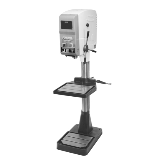
22-inch Variable Speed Drill Press
Models: J-2210, J-2230-2, J-2230-4
Model J-2230-2 shown
WMH TOOL GROUP, Inc.
2420 Vantage Drive
Elgin, Illinois 60124
Part No. M-354205
Ph.: 800-274-6848
Revision A 02/09
www.wmhtoolgroup.com
Copyright © 2009 WMH Tool Group, Inc.
Advertisement
Table of Contents

Related Manuals for Jet J-2210


Summary of Contents for Jet J-2210
- Page 1 Operating Instructions and Parts Manual 22-inch Variable Speed Drill Press Models: J-2210, J-2230-2, J-2230-4 Model J-2230-2 shown WMH TOOL GROUP, Inc. 2420 Vantage Drive Elgin, Illinois 60124 Part No. M-354205 Ph.: 800-274-6848 Revision A 02/09 www.wmhtoolgroup.com Copyright © 2009 WMH Tool Group, Inc.
-
Page 2: Warranty And Service
WMH Tool Group is consistently adding new products to the line. For complete, up-to-date product information, check with your local WMH Tool Group distributor, or visit jettools.com. WARRANTY JET products carry a limited warranty which varies in duration based upon the product (MW stands for Metalworking, WW stands for Woodworking). WHAT IS COVERED? This warranty covers any defects in workmanship or materials subject to the exceptions stated below. -
Page 3: Table Of Contents
Table of Contents Table of Contents............................3 Warning ................................. 4 Introduction ..............................6 Specifications ..............................6 Features and Terminology ..........................7 Unpacking and Setup............................ 8 Contents of the Shipping Container ......................8 Handle Assembly............................8 Electrical Connections ..........................8 Extension Cords ............................9 Operating Controls ............................ -
Page 4: Warning
Warning 1. Read and understand the entire owners manual before attempting assembly or operation. 2. Read and understand the warnings posted on the machine and in this manual. Failure to comply with all of these warnings may cause serious injury. 3. - Page 5 21. Check damaged parts. Before further use of the machine, a guard or other part that is damaged should be carefully checked to determine that it will operate properly and perform its intended function. Check for alignment of moving parts, binding of moving parts, breakage of parts, mounting and any other conditions that may affect its operation.
-
Page 6: Introduction
This manual is provided by WMH Tool Group covering the safe operation and maintenance procedures for the JET Model J-2210 and J-2230 Drill Presses. This manual contains instructions on installation, safety precautions, general operating procedures, maintenance instructions and parts breakdown. This machine has been designed and constructed to provide years of trouble free operation if used in accordance with instructions set forth in this manual. -
Page 7: Features And Terminology
Features and Terminology Figure 1... -
Page 8: Unpacking And Setup
Unpacking and Setup Open shipping container and check for shipping damage. Report any damage immediately to your distributor and shipping agent. Do not discard any shipping material until the Drill Press is installed and running properly. Compare the contents of your container with the following parts list to make sure all parts are intact. -
Page 9: Extension Cords
A power plug is not provided with the drill press. You may either connect the proper UL/CSA listed plug, or "hard-wire" the machine directly to a service panel, provided there is a disconnect near the machine for the operator. During hard- wiring of the machine, make sure the fuses have been removed or the breakers have been tripped in the circuit to which the drill press will... -
Page 10: Adjustments
The Depth Indicator (Figure 5) can be set for drilling depths up to 5”. 1. To set the Depth Indicator, lower the end of the drill against the surface into which the hole is to be drilled. 2. Loosen the handle on the pointer, and slide it to the approximate position on the depth gauge which matches your hole depth. -
Page 11: Belt Position (Speed Adjustment)
Be sure to remove drift key from spindle before starting the drill press. Belt Position (Speed Adjustment) 1. To change the speed range of the drill press, remove the access door on the side of the head. 2. Loosen the locking handles and pull the tension lever to release tension on the belt. -
Page 12: Drive Belt Replacement
Maintenance Make sure to disconnect electrical power to the drill press before performing maintenance, avoid possibility of inadvertent operation and exposure to potentially lethal voltage levels. Drive Belt Replacement 1. Remove the pulley access door. 2. Start drill press. Set speed control to highest speed. -
Page 13: Drilling Recommendations
Drilling Recommendations Feed Rates per Drill Size Speeds for Drilling Diameter of Drill Feed per Revolution The speed of a drill is usually measured in terms of the rate at which the outer periphery of the (inches) (inches) tool moves in relation to the work being drilled. Under 1/8 0.001 to 0.002 The common term for this is Surface Feet per... -
Page 14: Troubleshooting
Troubleshooting Trouble Probable Cause Remedy Motor overload protector tripped. Press motor overload reset button. Circuit breaker tripped. Re-set circuit breaker. Branch circuit breaker tripped or fuse Re-set branch circuit breaker/replace blown. fuse. Spindle does not turn. Open wire in switch circuit. Repair open circuit. -
Page 15: Replacement Parts
Replacement Parts Replacement parts are listed on the following pages. To order parts or reach our service department, call 1-800-274-6848 between 7:30 a.m. and 6:00 p.m. (CST), Monday through Friday. Having the Model Number and Serial Number of your machine available when you call will allow us to serve you quickly and accurately. -
Page 16: Parts List: Headstock Assembly
Parts List: Headstock Assembly Index No. Part No. Description Size 1 ....2210-201....Headstock ....................1 2 ....2210-202....Strain Relief Connector........PG13.5......3 3 ....2210-203....Handle Hub ....................1 4 ....TS-1504061 .....Socket Head Cap Screw........M8x30 ......5 5 ....2210-205....Pin ................ Ø8x30 ......1 ....2210-206A ....Handle Assembly (Item #6 &... - Page 17 57 .....2210-257....Bearing Housing ..................1 58 .....TS-1550061 .....Flat Washer............M8 ....... 3 59 .....2210-259....Driving Sleeve ..................1 60 .....2210-260....Key ............... 6x6x40 ......1 61 .....2210-261....Spindle Pulley ............1Ph......1 ....2210-261A ....Spindle Pulley ............3Ph......1 62 .....TS-1524061 .....Set Screw............. M8x25 ......2 63 .....2210-263....Sensor Seat ............
-
Page 18: Exploded View: Headstock Cover Assembly
Exploded View: Headstock Cover Assembly... -
Page 19: Parts List: Headstock Cover Assembly
38 .....TS-2284082 .....Screw ..............M4x8 ......2 39 .....2210-339....Plate ......................1 40 .....TS-2284082 .....Screw ..............M4x8 ......18 41 .....J-2210-341....Left Side Cover ..................1 42 .....2210-342....Plate ......................1 43 .....J-2210-343....Right Side Cover..................1 44 .....J-2210-344....Access Door..................... 1 45 .....TS-0561031 .....Hex Nut .............. -
Page 20: Exploded View: Base And Column Assembly
Exploded View: Base and Column Assembly... -
Page 21: Parts List: Base And Column Assembly
Parts List: Base and Column Assembly Index No. Part No. Description Size 1 ....J-2210-101....Base ......................1 2 ....J-2210-102....Lower Column Holder ................1 3 ....2210-103....Rack ......................1 4 ....2210-104....Column..................... 1 5 ....2210-105....Pinion Gear ....................1 6 ....2210-106....Worm Shaft ....................1 7 ....2210-107....Bushing .............. -
Page 22: Electrical Connections - 1 Phase, 230V
Electrical Connections – 1 Phase, 230V... -
Page 23: Electrical Connections - 3 Phase, 230V
Electrical Connections – 3 Phase, 230V... -
Page 24: Electrical Connections - 3 Phase, 460V
Electrical Connections – 3 Phase, 460V WMH Tool Group, Inc. 2420 Vantage Drive Elgin, Illinois 60124 Phone: 800-274-6848 www.wmhtoolgroup.com...
Need help?
Do you have a question about the J-2210 and is the answer not in the manual?
Questions and answers