Table of Contents
Advertisement
This .pdf document is bookmarked
Operating Instructions and Parts Manual
Drill Press
Models: J-2500, J-2530, J-2550
J-2530
J-2500
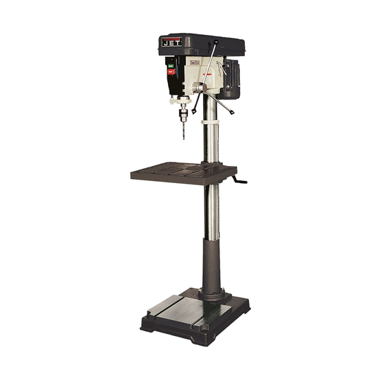
J-2550
WALTER MEIER (Manufacturing), Inc.
427 New Sanford Road
LaVergne, Tennessee 37086
Part No. M-354400
Ph.: 800-274-6848
Revision B 04/2012
www.waltermeier.com
Copyright © 2012 Walter Meier (Manufacturing), Inc.
Advertisement
Table of Contents

Related Manuals for Jet J-2500


Summary of Contents for Jet J-2500
-
Page 1: Drill Press
This .pdf document is bookmarked Operating Instructions and Parts Manual Drill Press Models: J-2500, J-2530, J-2550 J-2530 J-2500 J-2550 WALTER MEIER (Manufacturing), Inc. 427 New Sanford Road LaVergne, Tennessee 37086 Part No. M-354400 Ph.: 800-274-6848 Revision B 04/2012 www.waltermeier.com Copyright © 2012 Walter Meier (Manufacturing), Inc. -
Page 2: Warranty And Service
Walter Meier is consistently adding new products to the line. For complete, up-to-date product information, check with your local Walter Meier distributor, or visit waltermeier.com. WARRANTY JET products carry a limited warranty which varies in duration based upon the product. (MW = Metalworking, WW = Woodworking) Body Repair Kits Beam Clamps... -
Page 3: Table Of Contents
Adjustment ..............................10 Depth Stop Adjustment ..........................10 Changing Spindle Speeds .......................... 11 Return Spring Adjustment .......................... 11 Work Light (J-2500 and J-2530 only) ......................11 Table Tilt Adjustment ..........................12 Operation ..............................12 Installing Drills ............................12 Positioning the Workpiece .......................... 12 Using the Vise ............................ -
Page 4: Warnings
Warnings 1. Read and understand the entire owners manual before attempting assembly or operation. 2. Read and understand the warnings posted on the machine and in this manual. Failure to comply with all of these warnings may cause serious injury. 3. - Page 5 22. Give your work undivided attention. Looking around, carrying on a conversation and “horse-play” are careless acts that can result in serious injury. 23. Maintain a balanced stance at all times so that you do not fall or lean against the spindle or other moving parts.
-
Page 6: Introduction
Introduction The JET 15-Inch 16-Speed Drill Presses and 20-Inch 12-Speed Drill Presses, Models J-2500, J-2530 and J-2550, feature rugged cast iron design with ground-steel columns for drilling accuracy in metal, wood, and plastic. The head casting features a ball bearing spindle assembly, supported by four permanently-lubricated, heavy duty ball bearings that are mounted in an enclosed quill for extended life. -
Page 7: Shipping Contents
Shipping Contents Unpack the carton and verify that all parts listed below are included. Other Material Main Parts 1 ea Owner’s Manual 1 ea Head Assembly 1 ea Warranty Registration Card 1 ea Table 1 set Column and Table Bracket Assembly 1 ea Base Required Tools... -
Page 8: Assembly
2. Compare the contents of the shipping container with the list found above. Report any shortages or damage to your JET distributor. 3. Clean all rust protected surfaces with kerosene Figure 2 or a light solvent. Do not use lacquer thinner, 3. -
Page 9: Column Lock Handle
2. Rotate head assembly until sides of the pulley Column Lock Handle cover are parallel with the sides of the base. Referring to Figure 5: 3. Tighten two setscrews (A) with a 5mm hex Thread the column lock handle (D) into the table wrench (provided) until they are snug. -
Page 10: Chuck And Arbor Removal
Chuck and Arbor Removal Adjustment Referring to Figure 9: Depth Stop Adjustment 1. Unplug machine from the power source. Referring to Figure 10: 2. Raise the table until it is about seven inches below the chuck. To drill multiple holes at the same preset depth, use the depth stop: 3. -
Page 11: Changing Spindle Speeds
(D, Fig. 11). Refer to this chart whenever changing speeds. Note: The chart in Figure 12 is for models J-2500 and J-2530 only. To change spindle speeds: 1. Unplug the machine from the power source. -
Page 12: Table Tilt Adjustment
Table Tilt Adjustment Positioning the Workpiece The table tilt adjustments are made on the table Always place a piece of wood (or plywood) on the bracket under the table. table. This will prevent "splintering" or making heavy burrs on the underside of the workpiece as the drill To tilt the table (refer to Figures 14 and 15): breaks through. -
Page 13: Electrical
Disconnect the machine from the power source. the operator from electric shock. The JET drill press motor has four numbered leads that In the event of a malfunction or breakdown, grounding are factory connected for 115V operation, as shown in (A). -
Page 14: Troubleshooting
Troubleshooting Trouble Probable Cause Remedy Drill press unplugged from wall, or motor. Check all plug connections. Fuse blown, or circuit breaker tripped. Replace fuse, or reset circuit breaker. Drill press will not start. Cord damaged. Replace cord. Starting capacitor bad. Replace starting capacitor. -
Page 15: Replacement Parts
4B.... JDP15-1004B ..Body Column for J-2500 / JDP-15MF ........... 1 ....10600404A1 ....Column Assy for J-2530 / JDP-15M (includes #2A and #4A) ....1 ....10400401A1 ....Column Assy for J-2500 / JDP-15MF (includes #2B, #3 and #4B) ..1 5 ....TS-2229403 ....Hex Head Bolt ..........M10x40 ...... 4 6 .... - Page 16 Parts List – J-2500, J-2530 Index No. Part No. Description Size 45 .... 10604505 ....Scale Ring ..................1 50A..JDP15-1050 ....Spring Cap ..................1 51 .... 10605115 ....Shaft Seat ..................1 53 .... TS-0561052 ....Hex Nut............1/2"-20 ....... 1 54 .... 10605403 ....Quill Set Screw ..........M10-28 ...... 1 55 ....
- Page 17 Parts List – J-2500, J-2530 Index No. Part No. Description Size 128 ..TS-2285162 ....Cr. Re. Truss Hd. Tapping Screw ......M5-16 ....... 2 137 ..JDP15-1137 ....Switch Cover ..................1 138 ..TS-1533042 ....Cr. Re. Pan Head Screw ........M5-12 ....... 2 139 ..
-
Page 18: Exploded View - J-2500, J-2530
Exploded View – J-2500, J-2530... -
Page 19: Parts List - J-2550
Parts List – J-2550 Index No. Part No. Description Size 1 ....J-5627751 ....Base ....................1 2 ....J-5627761 ....Collar, Column..................1 3 ....5626231 ....Set Screw ............M10 x 40 mm ..... 1 4 ....5627771 ....Column ....................1 5 ....5627781 ....Screw, Hex Head..........M12 x 40 mm ..... 4 6 .... - Page 20 Parts List – J-2550 Index No. Part No. Description Size 57 .... 5629131 ....Washer, Rubber ................. 1 58 .... 5629141 ....Spindle ............MT3, Ø34 ....1 59 .... 5629151 ....Bearing, Ball .............6206ZZ ...... 1 60 .... 5629161 ....Bearing, Ball, Thrust .........2906 ......61 ....
- Page 21 Parts List – J-2550 Index No. Part No. Description Size 616 ..5513744 ....Screw, Clamping ................1 617 ..J-5518233 ....Clamp, Depth Stop support ..............1 618 ..5513746 ....Nut ....................1 700 ..5627711 ....Wrench, Allen ...........3 mm ......1 701 ..
-
Page 22: Exploded View - J-2550
Exploded View – J-2550... -
Page 23: Wiring Diagram
Wiring Diagram J-2500/J-2530 – 115V J-2500/J-2530 – 230V... -
Page 24: J-2550
J-2550 – 115V J-2550 – 230V...
Need help?
Do you have a question about the J-2500 and is the answer not in the manual?
Questions and answers