
Related Manuals for Jet JWS-22CS


Summary of Contents for Jet JWS-22CS
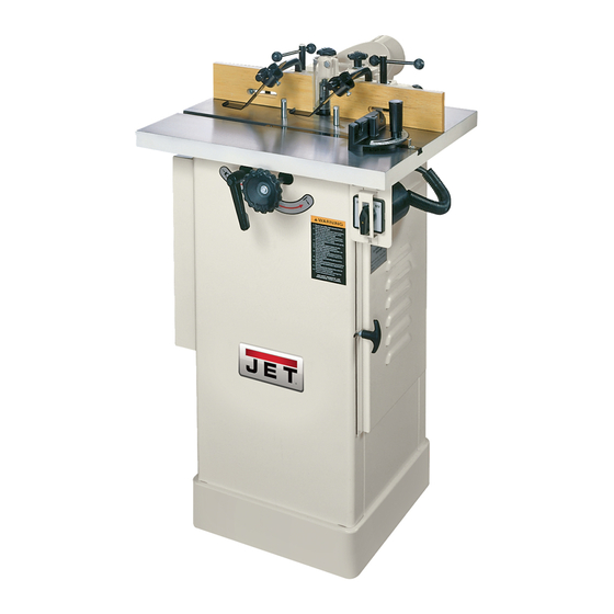
- Page 1 Operating Instructions and Parts Manual JWS-22CS Spindle Shaper WMH TOOL GROUP, Inc. 2420 Vantage Drive Elgin, Illinois 60124 Part No. M-708320 Ph.: 800-274-6848 Revision G 03/08 www.wmhtoolgroup.com Copyright © 2008 WMH Tool Group, Inc.
- Page 2 WMH Tool Group Authorized Service Centers can authorize warranty repair, assist you in obtaining parts, or perform routine maintenance and major repair on your JET® tools. For the name of an Authorized Service Center in your area call 1-800-274-6848.
- Page 3 Wear eye protection. Be sure keyed washer is directly under the spindle nut and the spindle nut is tight. Feed the workpiece against the rotation of the cutter. Do not use awkward hand positions. Keep fingers away from the revolving cutter. Use fixtures when necessary. Use the overhead guard when the adjustable fence is not in place.
- Page 4 • SECURE WORK. Use clamps or a vise to hold work when practical. It’s safer than using your hand and it frees both hands to operate the tool. • DON’T OVERREACH. Keep proper footing and balance at all times. • MAINTAIN TOOLS WITH CARE.
- Page 5 UL/CSA listed plug suitable for 230V The green operation. This plug is illustrated in Fig. E. Contact your local Authorized JET Service Center or qualified electrician procedures to install the plug. The shaper must comply with all local and national codes after the 230 volt plug is installed.
-
Page 6: Specifications
Now that you have purchased a shaper, it is a good time to consider a dust collection system. See your local JET distributor for the complete line of dust collectors and the full line of JET Dust Collector Hoses and Accessories. Customize your installation and obtain maximum performance with JET's dust hoods, hoses, clamps, fittings, and blast gates. - Page 7 Unpacking and Cleanup 1. Finish removing all contents from the shipping container. Do not discard any shipping material until the shaper is set up and running. 2. Inspect contents for shipping damage and report any damage to your distributor. 3. Clean all protected parts with kerosene. Do not use gasoline, paint thinner, or any cellulose-based solvent.
- Page 8 Arbor Removal and Installation All adjustments to the machine must be made with the power off and unplugged from the power source! Failure to comply may result in serious injury! safety shield been illustration purposes only! shaper without the safety shield! Failure to comply may result in serious injury! The arbor is mounted to the main spindle with a draw bar and a nut.
-
Page 9: Fence Adjustments
Collet Installation 1. Disconnect machine from the power source. 2. To set up the shaper for collet use, remove the arbor and clean the spindle taper (Fig. 5). 3. Raise the spindle fully by turning handwheel clockwise. 4. Pull the spindle locking mandrel out (A, Fig. 2) and turn to lock the main spindle. -
Page 10: Spindle Control
Table Ring Removal and Installation To remove the table ring(s): 1. Remove any collet or spindle assembly in the spindle. 2. Lower the spindle assembly completely. 3. Loosen and remove the three 1/4" x 5/8” cross point screws from the ring. 4. -
Page 11: Shaping With Collars And Starting Pin
3. The rear fence should be advanced to contact the work as shown in Figure 11. The rear fence will then be in line with the cutting circle. Shaping with Collars and Starting Pin Follow these rules when shaping with collars and starting pin for safest operation and best results: 1. - Page 12 3. The collar between cutters method, shown in Figure 18, has both the advantages and disadvantages of the first two methods. This method is used primarily where both edges of the work are to be shaped. Starting Pin Using the starting pin should only be attempted by advanced users! If you have never used this method before, it is recommended you get training...
-
Page 13: Troubleshooting
Troubleshooting Problem Shaper will not start Overload kicks out frequently Cutter does not come up to full speed Cuts are unsatisfactory Machine vibrates Possible Causes and Solutions: *Fuse blown or circuit breaker tripped Replace fuse or reset circuit breaker *Cord damaged Replace cord *Cord unplugged from the power source Plug in power cord... - Page 14 Machine vibrates bolts Edge splits off on cross grain cut grain Raised areas on shaped edge Work pulled from hand cutterhead Depth of cut not uniform fence Work burns several passes Cut height not uniform Cuts not smooth Spindle does not raise freely *Motor mounted improperly Motor must be properly mounted with snug nuts and *Characteristic of this type of cut...
- Page 15 Table and Fence Breakdown...
-
Page 16: Fence Breakdown
Fence Breakdown... - Page 17 Parts List for the JWS-22CS Shaper Index No. Part No. 1 ...JWS22CS-1 ...Table ..1 2 ...JWS22CS-2 ...Spindle Housing..1 2-1 ...JWS22CS-2-1 ...Spindle Locking Mandrel ..1 2-2 ...JWS22CS-2-2 ...Lock Washer ... M18.5 ... 1 3 ...JWS18HO-3...Cutter Spindle Bracket ..1 4 ...BB-6005ZZ...Ball Bearing...
- Page 18 Index No. Part No. Description Size 36 ...JTAS10-45 ...Handle..1 37 ...TS-0720091 ...Lock Washer ... 3/8 ... 4 38 ...TS-1540021 ...Hex Nut ... M6 ... 1 39 ...JTAS10-41 ...Spring..1 40 ...TS-1482101 ...Hex Cap Screw ... M6x50 ... 1 41 ...JWS22CS-41 ...Motor Plate...
- Page 19 Index No. Part No. 84 ...JWS18HO-84...Safety Shield ..1 85 ...JWS18HO-85...Fence Body..1 86 ...TS-0209021 ...Hex Socket Cap Bolt... 3/8x5/8 ... 2 87 ...JWS18HO-87...Lock Knob ... 3/8 ... 2 88 ...JWS18HO-88...Knob..2 89 ...TS-0680061 ...Washer... 1/2 ... 2 90 ...JWS18HO-90...Lock Handle ...
-
Page 20: Electrical Schematic
Electrical Schematic... - Page 21 Electrical Schematic for the Forward/Reverse Switch...
- Page 22 Notes...
- Page 23 Notes...
- Page 24 WMH TOOL GROUP, INC. 2420 Vantage Drive Elgin, IL 60124 800-274-6848 www.wmhtoolgroup.com...
Need help?
Do you have a question about the JWS-22CS and is the answer not in the manual?
Questions and answers