Advertisement
Advertisement
Table of Contents

Related Manuals for IMC Networks Access Converter/3


Summary of Contents for IMC Networks Access Converter/3
- Page 1 Access Converter/3 Operation Manual...
-
Page 2: Fcc Radio Frequency Interference Statement
At its option, IMC Networks will repair or replace at no charge the product which proves to be defective within such warranty period. This limited warranty shall not apply if the IMC Networks product has been damaged by unreasonable use, accident, negligence, service or modification by anyone other than an authorized IMC Networks Service Technician or by any other causes unrelated to defective materials or workmanship. -
Page 3: Table Of Contents
TABLE OF CONTENTS FCC Radio Frequency Interference Statement ............ii Warranty......................ii About the Access Converter/3 ................4 Installing the Access Converter/3 ................5 LED Operation....................6 Specifications .....................8 Safety Certifications....................9... -
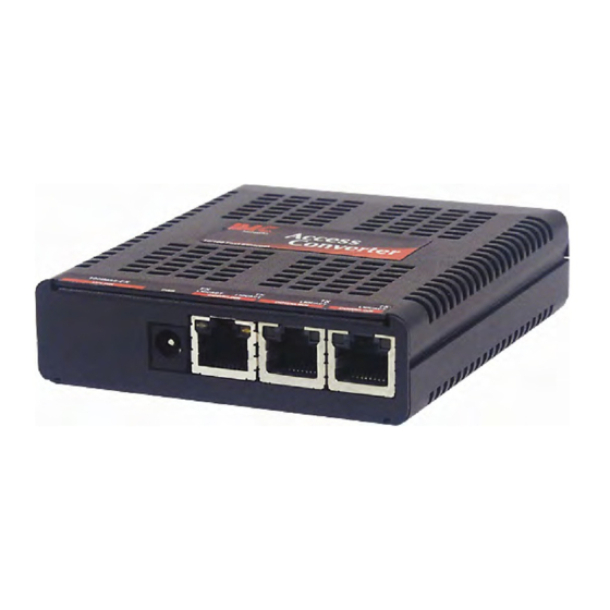
Page 4: About The Access Converter/3
The Access Converter/3 also protects against Broadcast storms, and allows packets of up to 1532 bytes to pass. The Access Converter/3 uses a universal external switching power adapter for 100 to 240 ±10% VAC input and 5 VDC output (included). -
Page 5: Installing The Access Converter/3
INSTALLING THE ACCESS CONVERTER/3 Install the Access Converter/3 as a table-top device, or mount to a wall surface with the appropriate bracket (included). To wall mount, use the supplied screws to attach the wall-mount bracket to the Access Converter/3, then simply mount the unit to the wall by tightening the screws (not supplied). -
Page 6: Led Operation
LED OPERATION Each Access Converter/3 includes diagnostic LEDs for troubleshooting. Fiber Uplink TX Downlink LED Front Uplink LED Back Twisted Pair Downlink Ports The LED indicator for the twisted pair downlink port is located on the RJ-45 connector of the downlink port next to the power connector. There are two LED functions for the twisted pair downlink ports. - Page 7 Twisted Pair Uplink Port When the Access Converter/3 is configured with a twisted pair uplink port, the LED location and functionality is the same as that for the downlink ports.
-
Page 8: Specifications
SPECIFICATIONS DC Input Voltage: AC Adapter Input Load: 100/240 ±10% VAC, 0.25A, 50/60 Hz, 5 VDC output with maximum output current of 1A Unit Power Consumption (Typical): 600 mA @ 5 Operating Temperature: 32° to 122° F (0° to 50° C) Storage Temperature: -4°... -
Page 9: Safety Certifications
Electrical Equipment Designed for use within Certain Voltage Limits (73/23/EEC). Certified to Safety of Information Technology Equipment, Including Electrical Business Equipment. For further details, contact IMC Networks. Class 1 Laser product, Luokan 1 Laserlaite, Laser Klasse 1, Appareil A’Laser de Classe 1... - Page 10 The information in this document is subject to change without notice. IMC Networks assumes no responsibility for any errors that may appear in this document. Access Converter/3 is a trademark of IMC Networks. Other brands or product names may be trademarks and are the property of their respective companies.
Need help?
Do you have a question about the Access Converter/3 and is the answer not in the manual?
Questions and answers