Advertisement
Quick Links
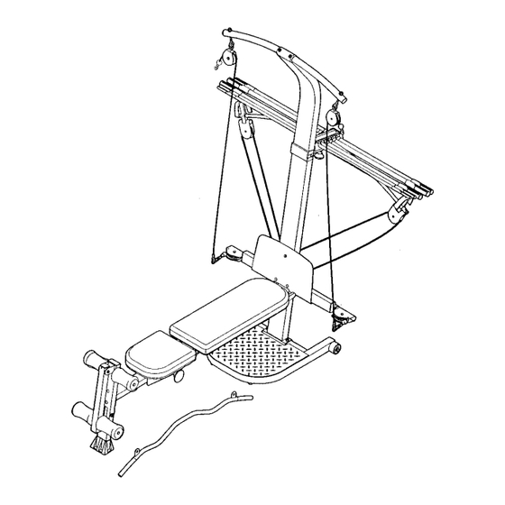
Model No. 831.153960
Serial No.
Write the serial number in the
space above for future reference.
Serial Number Decal (under seat)
www.TheCrossBow.com
Cr__M_'_,==
d_,,
TM
byWIEIDER
l
_
'_'::,,' .........
RESISTANCE SYSTEM EXERCISER
User's Manual
Sears, Roebuck
and Co., Hoffman
Estates,
IL 60179
Advertisement

Related Manuals for Weider Cross Bow Advantage 831.153960


Summary of Contents for Weider Cross Bow Advantage 831.153960
- Page 1 Cr__M_'_,== d_,, Model No. 831.153960 Serial No. Write the serial number in the space above for future reference. byWIEIDER '_'::,,' ..Serial Number Decal (under seat) RESISTANCE SYSTEM EXERCISER User's Manual www.TheCrossBow.com Sears, Roebuck and Co., Hoffman Estates, IL 60179...
- Page 2 TABLE OF CONTENTS WARNING DECAL PLACEMENT ............IMPORTANT PRECAUTIONS ............. BEFORE YOU BEGIN ..............ASSEMBLY ................ADJUSTMENTS ..............CABLE DIAGRAM ..............EXERCISE GUIDELINES ............... ORDERING REPLACEMENT PARTS ..........Back Cover WARRANTY ..............Back Cover Note: A PART IDENTIFICATION CHART and a PART LIST/EXPLODED DRAWING are attached in the center of this manual.
- Page 3 IMPORTANT PRECAUTIONS crum Keep children under 12 and pets away from the resistance system at all times. Keep hands and feet away from moving parts. tion while exercising.
- Page 4 BEFORE YOU BEGIN Thank you for selecting the innovativeCrossBow by after reading this manual, call 1-800-4-MY-HOME ® WELDER" ADVANTAGE resistance system. The resist- (1-800-469-4663). To help us assist you, please note ance system offers a selection of stations designed to the product model number and serial number before develop every major muscle group of the body.
- Page 5 ASSEMBLY • Tighten all parts as you assemble them, unless instructed to do otherwise. • As you assemble the resistance system, make sure all parts are oriented as shown in the draw- ings. The included _ Allen wrenche.e.e.e.e.e.e.e._J and the follow- ing tools (not included) are required for assem- bly: •...
- Page 6 Attach a Wheel (31) to the outside of the Base (1) with an M10 x 108mm Bolt (81), three M10 Washers (75), and an M10 Nylon Locknut (76). Do not overtighten the Nylon Locknut; the Wheel must be able to turn easily. Attach the other Wheel (not shown) in the same...
- Page 7 Attach the Let Tower (4) to the Upright (3) with four MIO x 25mm Button Head Bolts (87), and four M10 Lock Washers (103). Attach the Name Plate (89) to the Let Tower (4) with two M4 x 16mm Screws (62). -'"""...
- Page 8 Attach two 8mm Metal Spacers (97), a 60mm Metal Spacer (39), and two Bearing Wheels (46) to one end of the Seat Carriage (12) with an M8 x 104mm Bolt (60) and an M8 Nylon Locknut (65) _cond as shown. Be sure the parts are oriented as set of wheels shown in the inset drawing;...
- Page 9 12. Press two 25mm Square Inner Caps (54) into the indicated end of the Backrest Frame (15). Attach a Plastic Foot (53) to the Backrest Frame (15) with an M4 x 16mm Screw (62). Attach the two Guard Plates (17) to the inside of the Backrest Frame (15) with four M4 x 16mm Screws (62).
- Page 10 16. Locate the Crossbow Fulcrum (18) on the Lat Tower (4) (see the inset drawing). Slide the Crossbow Spacer (35) onto the rods on the Crossbow Fulcrum. Make sure the Spacer is oriented as shown in the drawing. Set the Crossbows into the Crossbow Spacer (35) in the following order: the 10-pound Removable Crossbow (67), the 20-pound Removable Rings on...
- Page 11 20. Wrap the Long Cable (80) under a 90mm Pulley (28) as shown. Attach the Pulley and a Pulley Guard (29) to the Upright (3) with an Mr0 x t13mm Button Head Bolt (40) and an M10 Nylon Locknut (76). Be sure the flat edge of the Pulley Guard is on the bottom.
- Page 12 Locate the Leg Lever Cable (32), which has two ends that are the same length and a third end that is longer. Route the longest end of the Leg Lever Cable (32) through the hole in the Front Leg (6), and attach it inside of the hole in the Leg Lever (7) with an M10 x 60ram Button Head Bolt (63) and an M10 Nylon Locknut (76).
- Page 13 ADJUSTMENTS This section explains how to adjust the resistance system. See the EXERCISE GUIDELINES on page 17 for important information about how to get the most benefit from your exercise program. Also, refer to the accompa- nying exercise guide to see the correct form for each exercise. Make sure all parts are properly tightened each time you use the resistance system.
- Page 14 ATTACHING THE ACCESSORIES To attach a Short Handle (49) to a high pulley, first attach the high pulley to the resistance system (see A'FI-ACHING THE HIGH PULLEYS AND LEG LEVER on page 13). Then, attach the Short Handle to the Short Cable (33) with a Cable Clip (51).
- Page 15 ADJUSTING THE BACKREST The Backrest (14) can be used in a level position or one of three inclined positions. To use the Backrest in a level position, secure the Seat Carriage (12) to the adjustment hole in the Bench Rail (5) next to the Front Leg (6) (see ADJUSTING THE SEAT on page 13).
- Page 16 USING THE REMOVABLE CROSSBOWS The Removable Crossbows (36, 67_ can be used to 67 36 exercise apart from the resistance system, as shown in the video or on the exercise guide. To remove a Crossbow, pull it out of the Crossbow Spacer (35). To replace the Removable Crossbows (36, 67), slide them into the Crossbow Spacer (35) from the side shown, so that the arrows on the rings point toward...
- Page 17 EXERCISE GUIDELINES THE FOUR BASIC TYPES OF WORKOUTS PERSONALIZING YOUR EXERCISE PROGRAM Muscle Building Determining the exact length of time for each workout, To increase the size and strength of your muscles, as well as the number of repetitions or sets completed, push them close to their maximum capacity.
- Page 18 slowly as you stretch and do not bounce. Ease into Rest for a short period of time after each set. The each stretch gradually and go only as far as you can ideal resting periods are: • Rest for three minutes after each set for a muscle without strain.
- Page 19 MONDAY EXERCISE RESISTANCE SETS REPS Date: AEROBIC EXERCISE TUESDAY Date: WEDNESDAY EXERCISE RESISTANCE SETS REPS Date: THURSDAY AEROBIC EXERCISE Date: RESISTANCE SETS FRIDAY EXERCISE REPS Date: Make photocopies of this page for scheduling and recording your workouts.
- Page 20 PART IDENTIFICATION CHART Refer to the drawings below to identify small parts used in assembly. The number in parentheses below each drawing is the key number of the part, from the PART LIST on the reverse side of this page. Note: Some small parts may have been pre-attached.
- Page 21 M10 x 65mm Button Head Bolt (70) M10x 53mmCarriageBolt (61) M10 x 68mm Button Head Bolt (56) M10 x 60ram Button Head Bolt (63) _\\\ \x_6!_m_'!!r!!g!!! !{,831 1/4" x 45mm Bolt (58) M10 x72mm Bolt (64) M10 x 42mm Button Head Bolt (71) M10 x 91ram Bolt (90) M10 x 25ram Button...
- Page 22 EXPLODED DRAWINGmModel NO. 831.153960 Ro2o3A / 35_ i_58 ._)°"_Y377 91 84 ..3_" _.43 76_. 94 76 74_J.J 71"___, _ f_r_74 _-24 I" 92 45 62.._ 102_ '_ 7_...
- Page 23 PART LIST--Model No. 831.153960 R0203A Key No. Qty. Description Key No. Qty. Description Base M8 x 114mm Axle Base Plate 1/4" x 45mm Bolt M8 Washer Upright Lat Tower M8 x 104mm Bolt Bench Rail M10 x 53ram Carriage Bolt M4 x 16mm Screw Front Leg M10 x 60mm Button Head Bolt...
- Page 24 .._iiii3_iiiiiiiiiiiiiiiiii!i!iii!iiiiil _"_q!iiii!ii!!!i!iiiiiii!ii!i!i Your Home For repair in your home of all major brand appliances, lawn and garden equipment, ....... or heating and cooling systems, no matter who made it, no matter who sold it! For the replacement parts, accessories, and user's manuals that you need to do-it-yourself. :::.::.: professional appliances...
Need help?
Do you have a question about the Cross Bow Advantage 831.153960 and is the answer not in the manual?
Questions and answers
I would like to purchase new cables and pulleys. Is there a package for this