Advertisement
Quick Links
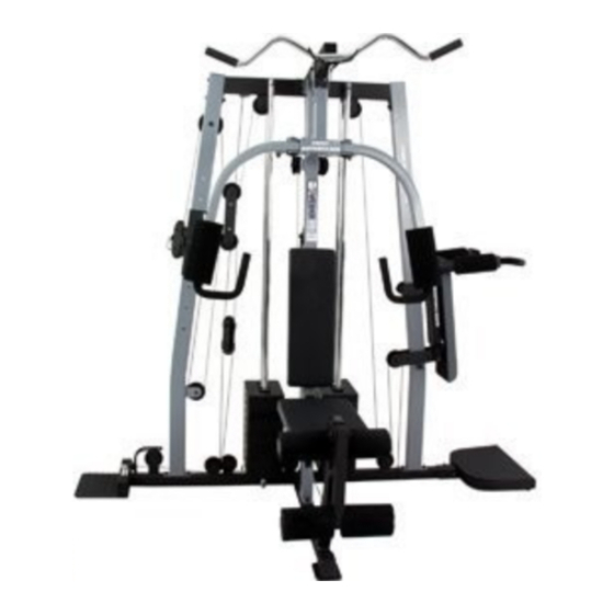
Model No. 831.153930
Serial No.
Write the serial number in the
space above for reference.
Serial Number Decal (under seat)
_"
X
E:
R
C
I _
E:.
E
Q
LI
I
P
M
E
N"V
[-0
Ol_m
HELPLINE!
!-800-736-6879
SEARS, ROEBUCK AND CO.
HOFFMAN ESTATES, IL 60179
I,ACAUTION
Read alll_'l_autionsand
Inl_uru_
tin
In _ls martial Ilefom ullng
arts_l_,
sa_t_
mimmd
for tUtu_
USER'S MANUAL
Patent Pending
r
www.weiderfitness.com
new products, prizes,
fitness tips, and much more!
Advertisement

Related Manuals for Weider PRO


Summary of Contents for Weider PRO
- Page 1 Model No. 831.153930 Serial No. USER'S MANUAL Write the serial number in the space above for reference. Serial Number Decal (under seat) _" N"V Ol_m HELPLINE! !-800-736-6879 Patent Pending SEARS, ROEBUCK AND CO. HOFFMAN ESTATES, IL 60179 I,ACAUTION Read alll_'l_autionsand Inl_uru_ In _ls martial Ilefom ullng www.weiderfitness.com...
-
Page 2: Table Of Contents
TABLE OF CONTENTS IMPORTANT PRECAUTIONS ............. BEFORE YOU BEGIN ..............ASSEMBLY ................ADJUSTMENTS ............... WEIGHT RESISTANCE CHART ............TROUBLESHOOTING ..............CABLE DIAGRAMS ..............ORDERING REPLACEMENT PARTS ..........Back Cover FULL 90 DAY WARRANTY ............Back Cover Note: A PART IDENTIFICATION CHART and a PART LIST/EXPLODED DRAWING are attached in the center of this manual. -
Page 3: Important Precautions
IMPORTANT PRECAUTIONS Read all Instructions in rids manual and in 13. Always disconnect the lat bar from the • e aCcompanylngltterature before using the weight system when performing an exercise weight system. U1at_ not-use the lat bar. It Is theresponslbmty of the owner to ensure 14. -
Page 4: Before You Begin
BEFORE YOU BEGIN Thank you for selecting the versatile WELDER ®PRO 1-800-736-6879, Monday through Saturday, 7 a.m. 4850 weight system. The WELDER®PRO 4850 weight until 7 p.m. Central "rime(excluding holidays). To help system offers an impressive array of weight stations us assistyou, please note the product model number designed to develop every major muscle group of the and serial number before calling. -
Page 5: Assembly
ASSEMBLY Make sure that you have the following tools: ka/umemu • Two adjustable wrenches _lng in rigs manual _,dealgned to • One standard screwdriver ensure-that the weightsystem can be assem- btedsuc==du.y byanyone. • One phillipsscrewdriver • One rubber mallet read t_e_on onthls pege. - Page 6 FRAME ASSEMBLY Locate and open the parts bags labeled "FRAME ASSEMBLY 1" and "FRAME ASSEMBLY 2." Press a 2" Square Inner Cap (105) intothe open end of the Long Base (120). Insert eight 5/16" x 2 1/2" Carnage Bolts (110) up through the Long Base (120) and the Short Base (2) as shown.
- Page 7 Press a 1 1/2" Square Inner Cap (67) into the square tube on the Butterfly.Upright (3). Slide the ButterflyUpright (3) onto the two indicated 5/16" x 2 1/2" Carriage Bolts(110) in the Short Base (2). Finger tighten a 5/16" Nylon Locknut (86) onto each Carriage Bolt, Do not tighten the Nylon Locknuta yet, Press a 2"...
- Page 8 Press a 2" x 3" Inner Cap (58) into the top of the Squat Upright (4). Slide the Squat Upright onto the _t58 two indicated5/16" x 2 1/2" Carriage Bolts(110) in the Long Base (120). Finger tighten a 5/16" Nylon Locknut (86) onto each Carriage Bolt.
- Page 9 Attach a Roller (39) and two 5/16" Washers (90) between the indicatedset of holes in the Squat Slider (38) with a 5/16" x 3 1/2" Bolt (94), two 5/16" Washers (90), and a 5/16" Nylon Locknut (86) as shown. Assemble the other three Rollers (39) to the Squat Slider (38) In the same manner.
- Page 10 12. Attach the Top Frame (6) between the Squat Upright (4) and the Swivel Upright (5) with four 5/16" x 3 3/4" Bolts (92), the two Short Frame Plates (52), and two /"_ 5/16" Nylon Locknuts(86) as shown. Do not tlghtsn the Bolts and Locknuts yet.
- Page 11 16. Press a 1 112"x 2" Inner Cap (21) into the R_ght Lubricate ButterflyArm (26). Wet the lower end of the Arm with soapy water. Slide a Long Pad (54) onto the Arm. Slide two Nut Clips (106) onto a Press Handle (27). , .-113 Attachthe Press Handle to the Right ButterflyArm (26) with two 5/16"...
- Page 12 19. Route the Swivel High Cable (74) throughthe Swivel Upright (5) and over a 4 1/2" Pulley (119). Attach the 91 18 Pulley inside the Updghtwith a 3/8" x 2 3/4" Bolt (101), two 3/8" Washers (91), two 1/2" Spacers (89), and a 318"Nylon Locknut(87).
- Page 13 24. Remove the preettached 3 1/2" Pulleys (78) from the Offset Double "U"-bracket (61). Wrap the Swivel Cable (17) around a 3 1/2" Pulley (78). Attach the Pulley to the Offset Double "U"- bracket (61) with a 3/6" x 1 3/4" Bolt (93) and a 3/8" Nylon Locknut (87).
- Page 14 29. Wrap the Lat Cable (88) around a 3 1/2" Pulley (78). Attach the Pulley and a Long Cable Trap (102) to the Top Frame (6) with a 318"x 1 314"Bolt (93) and a 318"Nylon Jamnut (113). Make sure the Cable Trap Is turned to hold the Cable In the groove of the Pulley.
- Page 15 34. Remove the preettached 3 1/2" Pulleys (78) from the Double "U"-bmcket (62). Wrap the ButterflyCable (69) under a 3 1/2" Pulley (78). Attach the Pulley to the Double "U"-bracket (62) with a 3/8" x 1 3/4" Bolt (93) and a 3/8" Nylon Locknut (67).
- Page 16 39. Route the Leg Lever Cable (75) under a 4 112" Pulley (119). Attach the Pulley and a Large Cable Trap (121) to the indicated side oi the Buttedly Upright (3) with a 3/8" x 3 3/4" Bolt (122), a 3/8" Washer (91), and a 3/8"...
- Page 17 44. Wrap the Swivel Low Cable (72) over a 3 1/2" Pulley (78). Attach the Pulley to the Offset Double "U"- bracket (61) with a 3/8" x 1 3/4" Bolt (93) and a 3/8" Nylon Locknut (87). 45. Wrap the Swivel Low Cable (72) under a 3 1/2" Pulley (78).
- Page 18 49. Wrap the Swivel Low Cable (72) over a 3 112" Pulley (78). Attach the Pulley and a Cable Trap (68) between the lower set of holes in the "U"-bracket (64) with a 3/8" x 2" Bolt (100) and a 3/8' Nylon Locknut (87).
- Page 19 53. Wrap the Squat Cable (73) under a 3 1/2" Pulley (78). Attach the Pulley and a Cable Trap to the sec- ond set of holes from the top in the indicated brack- et on the Long Base (120) with a 3/8" x 2" Bolt (100) and a 318"Nylon Locknut (87).
- Page 20 57. Attach the Seat (16) to the Seat Frame (8) with two 114"x 3/4" Screws (114), a 1/4" x 2 1/2" Screw (99), and a 1/4" Washer (97). 58. Attach the Butterfly Backrest (15) to the Butterfly Updght (3) with four 1/4" x 3/4" Screws (114). ,114 59.
- Page 21 61. Unscrew the Adjustment Knob (115) and remove it from the Squat Bracket (37). Turn the Squat Backrest (35) so that the four screw holes are clos- er to the bottom of the Squat Backrest than the top. Attach the Squat Backrest to the Squat Bracket with four 114"x 314"Screws (114).
-
Page 22: Adjustments
ADJUSTMENTS The instructionsbelow describe how each part of the weight system can be adjusted. Refer to the exercise guide accompanying this manual to see how the weightsystem should be set up for various exercises.IMPOR- TANT: When attaching the let bar, row bar, or handle, make sure that the attachments are In the correct starting position for the exercise to be performed. - Page 23 ADJUSTING THE SQUAT ARM OR SWIVEL CARRIAGE To adjustthe height of the Squat Arm (32), first turn the Adjustment Knob (115) on the Squat Bracket (37) counterclockwiseseveral turns to loosen it. Next, pull the Handle and slide the Squat Bracket up or down to the desired position.
-
Page 24: Weight Resistance Chart
WEIGHT RESISTANCE CHART The chart below shows the approximate weight resistance at each weight station. "Top"refers to the 10-pound top weight. The other numbers refer to the 10-pound weight plates. The butterflyarm resistance listedis the resistance for each butterfly arm. Note: The actual realatance at each weight station may vary due to differ- ences In Individual weight plates as well as friction between the cables, pulleys, and weight guides. -
Page 25: Troubleshooting
TROUBLESHOOTING Make sure all parts are propedytightenedeach time the weightsystem is used. Replace any worn parts immedi- ately. The weight system can be cleaned using a damp clothand mild non-abrasivedetergent. Do not use solvents. TIGHTENING THE CABLES Woven cable, the type of cable used on the weight system, can stretch slightlywhen it is first used. If there is slack in the cables before resistance is felt, the cables should be tightened. -
Page 26: Cable Diagrams
CABLE DIAGRAMS The cable identificationchart below shows the ends of each cable and the lengths of the cables. The cable dia- grams on this page and the followingpage show the proper routingof the cables. The numbers in the diagrams show the routes of the cables. Use the diagrams to make sure that the cables have been assembled correctly. IMPORTANT: If the cables have not been cor_=ctly routed, the weight system wnl not function properly and damage may occur. - Page 27 Swivel Low Cable (75) Cable (72) Leg Lever Swivel Cable (17)
- Page 28 This chart is provided to help you identify the small parts used in assembly.The number in parenthesis below each part refers to the key number of the part from the PART LIST in the center of this manual. Important: Some parts may have bean pre-aseambled for shipping purposes. If you cannot find a part In the parts bags, check to sea if it has bean pre-assembled.
- Page 29 1" Round Inner Cap (29) 1 112" x 2" Inner Cap (21) II II II II 2" x 2 1/2" Inner Cap (125) 2" Square Inner Cap (105) III II II 1 112"Square Inner Cap (67) 2" x 3" Inner Cap (58)
- Page 30 PART IDENTIFICATION CHART--Model No. 831.153930 R11oz_ 1/2" Nut (118) 1/2" Washer (1) 318" Nylon Locknut (87) 4 1/2" Pulley (119) ©8 (Not shown to scale) r-=_==_ 3/8" Washer (91) 3/8" Jamnut (113) Nylon t-c_J "V" Pulley (55) (Not shown to scale) 5116"...
- Page 31 L_\\\\\\I 5116" x 2 112"Carriage Bolt (1 3/8" x 2 1/2" Carriage Bolt (1 _\\\\\\\1 1/4" x 1 112" Bolt (99) 5/16" x 2 1/2" Bolt (59) 3/8" x 2" Bolt (100) 3/8" x 2 1/2" Bolt (18) L_\\\\\\I (93) 3/8"...
- Page 32 SAVE THIS PART LIST/EXPLODED DRAWING FOR FUTURE REFERENCE...
- Page 33 PART LIST--Model No. 831.153930 Rl10Z Qty. Description Qty. Description Qty. Description 1/2" Washer Lat Cable Swivel Carriage Short Base Butterfly Frame 1/2" Spacer 5/16" Washer Butterfly Upright Weight Tube Bumper 3/8" Washer Squat Upright Weight Bumper 5/16" x 3 3/4" Bolt Swivel Upright Weight Pin 5/16"...
-
Page 35: Full 90 Day Warranty
SEARS The model number and sedal number of your WELDER®PRO 4850 weight system are listed on a decal attached to the frame. Model No. 831.153930 See the front cover of this manual to find the locationof the decal. QUESTIONS? All replacement parts are available for immediate purchase or special order when you visit your nearest SEARS Service If you find that: Center.
Need help?
Do you have a question about the PRO and is the answer not in the manual?
Questions and answers