Table of Contents
Advertisement
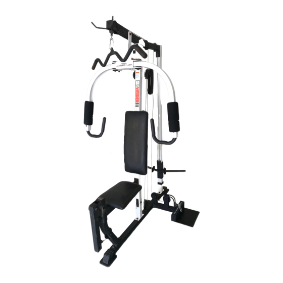
MEIDER 2100
Model No. 831.159010
Serial No.
Write the serial number in the
space above for reference.
Serial Number Decal (under seat)
_"
X F-. R C
I S
E.
EQUIPMENT
HELPLINE!
!-800-736-6879
SEARS, ROEBUCK AND CO.
HOFFMAN ESTATES, IL 60179
USER'S MANUAL
www.weiderfit
ness.com
new products, prizes,
fitness tips, and much more!
Advertisement
Table of Contents

Related Manuals for Weider 2100


Summary of Contents for Weider 2100
- Page 1 MEIDER 2100 Model No. 831.159010 USER'S MANUAL Serial No. Write the serial number in the space above for reference. Serial Number Decal (under seat) _" X F-. R C EQUIPMENT HELPLINE! !-800-736-6879 SEARS, ROEBUCK AND CO. HOFFMAN ESTATES, IL 60179 www.weiderfit ness.com new products, prizes,...
-
Page 2: Table Of Contents
TABLE OF CONTENTS IMPORTANT PRECAUTIONS ............. BEFORE YOU BEGIN ..............ASSEMBLY ................ADJUSTMENTS ..............WEIGHT RESISTANCE CHART ............CABLE DIAGRAM ..............EXERCISE GUIDELINES ..............ORDERING REPLACEMENT PARTS ..........Back Cover LIMITED WARRANTY ............Back Cover Note: A PART IDENTIFICATION CHART and a PART LIST/EXPLODED DRAWING are attached in the center of this manual. - Page 3 IMPORTANT PRECAUTIONS WARNING: To reduce the rlsk of serious injury, reed the following Important precau- tions before using the weight system. Read all Instructions in this manual and In 11. Make sure that the cables remain on the pul- the accompanying literature before using the leys at all times.
-
Page 4: Before You Begin
BEFORE YOU BEGIN Thank you for selecting the versatile WELDER ®2100 1-800-736-6879, Monday through Saturday, 7 a.m. weight system. The WELDER" 2100 offers a selection until 7 p.m. Central Time (excluding holidays). To help of weight stations designed to develop every major us assist you, please note the product model number muscle group of the body. -
Page 5: Assembly
ASSEMBLY • As you assemble the weight system, make sure all parts are oriented as shown in the drawings. • For help identifyingsmall parts, use the PART The following tools (not Included) are required for assembly: • two adjustable wrenches •... - Page 6 Attach the Rear Upright (7) to the Rear Base (3) with the two indicated M10 x 65mm Carriage Bolts (57) and two M10 Nylon Locknuts (71). Press a 38mm Square Inner Cap (41) intothe tube on the Front Upright (6). Attach the Front Upright (6) to the Front Base (1) with the two indicated M10 x 65mm Carriage Bolts (57) and two M10 Nylon Locknuts (71).
- Page 7 Press a 50mm Square Inner Cap (22) into the end of the Top Frame (8). Attach the Top Frame (8) to the Front Upright (6) with two M10 x 70mm Bolts (58), the 90mm Space Support Plate (21), and two M10 Nylon Locknuts(71).
- Page 8 Press a 40mm x 50mm Inner Cap (23) intothe indicatedend of the Right ButterflyArm (11). Wet the bottom end of the Arm with soapy water. Slide a Large Foam Pad (19) onto the Arm. Attach a Pivot Bracket (48) to the Right Butterfly Arm (11) with an M10 x 50mm Bolt (62) and an M10 Nylon Locknut (71).
- Page 9 12. Locate the Butterfly Cable (46). Attach the Butterfly Cable to the indicated Pivot Bracket (48) with an M8 x 27mm Shoulder Bolt (63) and an M8 Nylon Locknut (70). 13. Wrap the Butterfly Cable (46) around a "V"-Pulley (39). Attach the Pulley and a Long Cable Trap (40) to the bracket on the Front Upright (6) with an M10 x 55mm Bolt (69) and an M10 Nylon Locknut (71).
- Page 10 16. Attach the ButterflyCable (46) to the indicated Pivot Bracket (48) with an M8 x 27mm Shoulder Bolt (63) and an M8 Nylon Locknut (70). 17. Locate the High Cable (45). Route the eyelet end of the Cable up through the Top Frame (8) and around a 90mm Pulley (38).
- Page 11 20. Wrap the High Cable (45) around a 9Omm Pulley (38). Attach the Pulley inside the Top Frame (8) with an M10 x 70mm Bolt (58), two M1OWashers (26), two 13mm Spacers (34), and an M10 Nylon Locknut (71). 21. Attach the eyelet end of the High Cable (45) to the M10 x 20mm Bolt (67) in the bracket on the Weight Carriage (14) with an M1O Nylon Locknut (71).
- Page 12 24. Wrap the Low Cable (47) around a 90mm Pulley (38). Attach the Pulley and a Cable Trap (44) to the second set of holes from the bottomof the two Pulley Plates (36) with an M10 x 47mm Bolt (61) and an M10 Nylon Locknut (71). Be sure the Cable Trap Is turned to hold the Cable In the Groove of the Pulley.
- Page 13 28. Route the Low Cable (47) through the Seat Upright (73) and under a 90mm Pulley (38). Attach the Pulley inside the Seat Uprightwith an M10 x 65mm Bolt (59), two M10 Washers (26), two 13mm Spacer (34), and an M10 Nylon Locknut (71).
-
Page 14: Adjustments
32. Insert the two LockingPins (53) into the Butterfly Frame (9). Attach the tether on the Pins to the Butterfly Frame with the M4 x 10mm Screw (68). 33. Make sure that all parts have been properly tightened. The use of all remaining parts will be explained in ADJUSTMENTS, below. -
Page 15: Weight Resistance Chart
ADDING WEIGHTS TO THE WEIGHT CARRIAGE To add resistanceto the weight system, slide an equal amount of weight (not included)onto each side of the Weight weight tube on the Weight Carriage (14). Be sure that the weightsare pushed against the weight stops. Note: Due to the cables and pulleys, the actual amount of Weight reslstance at each exerclse statlon may vary from... - Page 16 WEIGHT RESISTANCE CHART This chart shows the approximate weight resistance at each weight station. The column labeled =WEIGHT" refers to the amount of weight, in pounds, placed on the weight carriage. The weight resistance shown for the butterfly arm station is for each butterfly arm. Note: The actual resistance at each station may vary due to friction between the cables, pulleys, and weight carriage.
-
Page 17: Cable Diagram
CABLE DIAGRAMS The cable diagrams below show the proper routingof the ButterflyCable (46), the High Cable (45), and the Low Cable (47). Use the diagrams to make sure that the cables and the cable traps have been assembled correctly. If the cables have not been correctly routed, the weight system will not function properlyand damage may occur. The numbers show the correct route for each cable. -
Page 18: Exercise Guidelines
EXERCISE GUIDELINES THE FOUR BASIC TYPES OF WORKOUTS PERSONALIZING YOUR EXERCISE PROGRAM Muscle Building Determiningthe exact length of time for each workout, To increase the size and strength of your muscles, as well as the number of repetitionsor sets completed, push them close to their maximum capacity.Your mus- is an individualmatter. - Page 19 Rest for a short period of time after each set. The slowly as you stretch and do not bounce. Ease into ideal resting periods are: each stretchgradually and go only as far as you can • Rest for three minutes after each set for a muscle without strain.
- Page 20 This chart is provided to help you identifythe small parts used in assembly. The number in parenthesisbelow each part refers to the key number of the part from the PART LIST in the center of this manual. Important: Some parts may have been pre-aesembled for shipping. If you cannot find a part In the parts bags, check to see If It has been pre-assembled.
- Page 21 MIO x 28ram Shoulder Bolt (78) M6 Washer (35) MIO Washer (26) MIO x 47ram Bolt (61) ©U MIO x 50mm Bolt (62) MIO Nylon Locknut (71) M5 Washer (75) MIO x 55ram Bolt (69) M8 Nylon Locknut (70) M6 x 65ram Bolt (65) M8 x 27ram Shoulder Bolt (63) MIO x 65ram Bolt (59) MIO x 20mm Bolt (67)
- Page 22 PART IDENTIFICATION CHART--Model No. 831.159010 R10O2A 90mm Pulley (38) (Not shown to scale) "V"-Pulley (39) (Not shown to scale) 31ram Round Inner Cap (24) 19ram Round Inner Cap (27) 25ram Round Inner Cap (33) 40ram x 50mm Inner Cap (23) 38ram Square Inner Cap (41) 5Omm Square Inner Cap (22) 50mm x 75mm Inner Cap (29)
- Page 23 SAVE THIS PART LIST/EXPLODED DRAWING FOR FUTURE REFERENCE...
- Page 24 PART LIST--Model No. 831.159010 R1002A Key No. Qty. Descrtptlon Key No. Qty. Description Front Base Handgrip Center Base Cable Trap Rear Base High Cable Leg Lever Butterfly Cable Seat Frame Low Cable Front Upright Pivot Bracket Rear Upright Chain Top Frame M10 x 82mm Bolt ButterflyFrame Handle...
- Page 26 SEARS The model number and serial number of your WELDER ®2100 weight system are listed on a decal attached to the frame. See Model No. 831.159010 the front cover of this manual to find the locationof the decal. All replacement parts are available for immediate purchase or QUESTIONS? special order when you visit your nearest SEARS Service Center.
Need help?
Do you have a question about the 2100 and is the answer not in the manual?
Questions and answers
Yes I need a manual for the 2100 machine and need to replace the cables