Table of Contents
Advertisement
®
Model No. 831.154031
Sedal No.
Write the seriaU number in the
space above for reference.
SeriaU Number DecaU(under seat)
• Assembly
• Adjustments
• Troubleshooti
ng
Part List and Drawing
WEIGHT SYSTEM EXERCISER
User's Manual
,&CAUTION
Read all precautions
and instruc-
tions in this manual before using
this equipment.
Save this manu-
aJ for future reference.
Sears, Roebuck and Co., Hoffman Estates, IL 80179
Advertisement
Table of Contents

Related Manuals for Weider PRO 4900


Summary of Contents for Weider PRO 4900
- Page 1 ® Model No. 831.154031 Sedal No. Write the seriaU number in the space above for reference. WEIGHT SYSTEM EXERCISER User's Manual SeriaU Number DecaU(under seat) • Assembly • Adjustments • Troubleshooti Part List and Drawing ,&CAUTION Read all precautions and instruc- tions in this manual before using this equipment.
- Page 2 TABLE OF CONTENTS WARNING DECAL PLACEMENT ............. HMPORTANT PRECAUTHONS ..............BEFORE YOU BEGIN ..............ASSEMBLY ................ADJUSTMENTS ................WEHGHT RESHSTANCE CHART .............. CABLE DHAGRAM ................. MAHNTENANCE ................EXERCHSE GUHDELHNES ..............ORDERHNG REPLACEMENT PARTS ..........Back Cover FULL 90-DAY WARRANTY ............Back Cover Note: A PART HDENTHFHCATHON C HART and a PART LHST/EXPLODED DRAWHNG are attached in the center of this manual...
- Page 3 iMPORTANT PRECAUTIONS AWARNtNG: To reduce the risk ofserious injury, read t he re,owing important precautions before using the weight system. Read aH instructions in this manual before 10. Make sure that the cables remain on the puF using the weight system. Use the weight sys- ieys at all times, if the cables bind as you are tern only as described...
-
Page 4: Overview
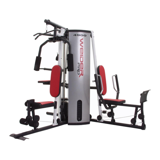
BEFORE YOU BEGIN Thank you for sebcting the versatib WELDER _> PRO reading this manual, call 1-800-4-MY-HOME _ 4900 weight system, The weight system offers an (1-800-469-4663), To help us assist you, phase note impressive array of weight stations designed to deveP the product model number and serial number before op every major muscle group of the body, Whether calling, The model number is 831,154031, The serial... - Page 5 ASSEMBLY Make sure you have the following too_s: Make Assembmy Easier for Yourself Two adjustable wrenches Everything in this manual is designed to One standard screwdriver ensure that the weight system can be assem- bled successful y by anyone, Before begin- * One phillips screwdriver ning assembly, make sure to read the...
-
Page 6: Frame Assembly
Before beginning assembly, make sul'e you understand the informationin the box on page 5. Refer to the PART _DENT_F!CAT_ON CHART i n the center of this manual f0r help Insert four M8 x 75mm Carriage Bolts (84) up through the Right Base (1), Note: it may be he_pfu_ to piece a piece of tape over the bott heads to hoJd them in place. - Page 7 Attach the Rear Upright (6) to the Rear Base (3) with the two indicated M8 x 75mm Carriage BoUts (84) and two M8 NyUonLocknuts (115), Do not tighten the Locknuts yet. 115 / Attach the Right Upright (4) to the Right Base (1) with the two indicated M8 x 75mm Carriage BoUts (84) and two M8 NyUonLocknuts (115), Do not tighten the Locknuts...
- Page 8 Attach the Left Upright (5) to the Left Base (2) with the two indicated M8 x 75mm Carriage BoUts (84) and two M8 NyUonLocknuts (115), Do not tighten the Locknuts yet, HoUdthe Left Top Frame (8) between the Left Upright (5) and the Rear Upright (6), Attach the Pull-up Arm (19) and the Left Top Frame to the Rear Upright with two M8 x 83mm BoUts(89), two M8 Washers (117), and two M8 NyUon Locknuts...
- Page 9 10. identify the Front Weight Guides (136), which have the Hockhobs cioser to the center than the Rear Weight Guides (24). Orient the Weight Guides with the hobs cioser to the bottom. Attach the Front Weight Guides (136) to the Right Base (1) with an M10 x 155mm Boit (130), two M10 Washers (116), and an M10 Nyion Locknut (114).
- Page 10 12, Attach the Front Weight Guides (136) to the Right Top Frame (7) with two MIO x 38mm Screws (82) and two MIO Washers (116), Repeat this step with the Rear Weight Guides (24). 13, Orient the Buttediy Frame (22) as shown, Attach the Butterfly Frame to the Right Upright (4) with two M8 x 72mm Bolts (91), two M8 Washers (117), and two M8 Nylon Locknuts (115), Do not...
-
Page 11: Arm Assenbly
16, Grease an M10 x 108mm Bolt (99), Orient the ; 4_ 13 Press Frame (13) as shown, Attach the Press Frame to the Left Base (2) with the Bolt and an M10 Nylon Locknut (114), Do not overtighten the Locknut; the Press Frame must be able to pivot easily. - Page 12 19, Attach the Leg Bumper (76) to the Right Seat Frame (9) with an M4 x 16mm Serf-tapping Screw (113) and an M4 Washer (131), Grease an MIO x 75mm BoUt(104), Attach the Leg Lever (11) to the Right Seat Frame (9) with the BoUtand an MIO NyUon Locknut (114), Make sure the "U'-rod is on the indicated...
-
Page 13: Cable Assembly
22, Refer to the CABLE DmAGRAMS on pages 27 and 28 as you assemble the cables and to identify the cables. _114 Locate the Lat Cable (71). Route the CaMe up through the Right Top Frame (7) and over a 90mm Pulley (39). - Page 14 27, Route the Lat Cable (71) over a 90mm Pulley (39) and down through the Left Top Frame (8), \\\\ Attach the Pulley inside the Top Frame with an MIO x 80mm Bolt (111), two MIO Washers (116), two 19mm Spacers (77), and an MIO Nylon Locknut (114), 28, Wrap the Lat Cable (71) under a 90mm Pulley (39), Attach the Pulley, a Small Cable Trap (48),...
- Page 15 32, Wrap the Ab CaMe (72) over a "V"-puHey (40), Attach the "V"opuHey, a CabUe Trap (49), an M10 Washer (116), and two Full Finger Guards (43) to the Right Upright (4) with an MIO x 61mm BoUt (90) and an MIO NyUonLocknut (114), Make sure the Cable Trap is oriented to hold the Cable in the groove of the Pu[ley.
- Page 16 36, Grease an M8 x 22mm ShouUder BoUt(88), Attach the Ab CaMe (72) to the bracket on the Right Upright (4) with the BoUtand an M8 NyUon Locknut (115), Make sure the fiat edge of the 115. Cable is against the bracket on the Upright Flat Edge 37, Locate the Leg Lever Cable (70).
- Page 17 41, Wrap the Leg Lever CaMe (70) under a 90mm Pulley (39), Attach the Pulley and two Half Finger Guards (42) to the Right Base (1) with an MIO x 48mm BoUt(101) and an MIO Nylon Locknut (114), Make sure the Finger Guards are orient- ed as shown.
- Page 18 46. Set an M12 Washer (129) on top of the Short Weight Tube (123). Thread an M12 Nut (128) aH the way onto the Leg Lever CaMe (70). Thread the Leg Lever CaMe (70) into the Short Weight Tube (123). Tighten the M12 Nut (128) against the M12 Washer (129).
- Page 19 51, Route the Right Stack Cable (70) down through the Right Top Frame (7) and over a 90mm Pulley (39), Attach the Pulley and a Small Cable Trap (48) inside the Top Frame with an MIO x 80mm Bolt (111), two MIO Washers (116), a 19mm Spacer (77), a 16mm Spacer (124), and an MIO Nylon Locknut (114), Make sure the 16ram Spacer and the Small Cable Trap are on the...
- Page 20 56, Wrap the Press CaMe (69) around a 90mm Pulley (39), Attach the Pulley, two HaUl Finger Guards (42), a Small CaMe Trap (48), and an MIO Washer (116) to the Left Upright (5) with an MIO x 108mm BoUt(99), an MIO Washer (116), and an MIO NyUonLocknut (114), Make sure the CabJe Trap and Finger Guards are oriented shown.
- Page 21 61, Attach the end of the Leg Press CaMe (69) to the "U"°bracket (50) with an M8 Washer (117) and an M8 NyUon Locknut (115), Note: Do not complete- ly tighten the Locknut; it shouJd be tightened so that only two threads of the Cabte show past the Locknut, as shown in the inset draw- ing.
- Page 22 65, Attach the Lock Hate (80) to the Right Seat Frame (9) with an M8 x 69mm ShouUder BoUt (87), an M8 Washer (117), and an M8 NyUonLocknut (115), Do not overtighten the Locknut; Lock Plate must be able to pivot easily. Attach the Leg Pin (83) to the Right Seat Frame (9) with an M4 x 16mm SeUfotapping Screw (113), Unsert the Leg Pin through the Lock Hate (80)
- Page 23 67, SHde the Pad Tube (31) through the Right Seat Frame (9), SHde two SmaHH Foam Pads (32) onto the Pad Tube, Press two Foam Caps (58) into the Pad Tubes, Repeat this step with the Leg Lever (!1}. 32 / 68, Attach the Knee Pad (30) to the Dip Assist (21) with four M6 x 16mm Screws (85), 69, Make sure that aHH parts have been properHy tightened, The use of the remaining parts wHH be expHained in...
- Page 24 ADJUSTMENTS This section explains how to adjust the weight system, See the EXERCISE GUiDELiNES on page 30 for important information about how to get the most benefit from your exercise program, Abo, refer to the accompanying exer- cise guide to see the correct form for each exercise, Make sure all parts are properly tightened each time the weight system is used, Replace any worn parts immediate°...
- Page 25 ADJUSTING THE BACKREST To adjust the position of the UeftBackrest (28), disen- gaging the Knob (121) from the Left Upright (5) and move the Backrest to the desired position. Reengage the Knob into the Left Upright and the Backrest Frame (27). Make sure the Knob is fulty tightened. LOCKING THE WEIGHT STACK Lock a weight stack by inserting a Lock Pin (44) through a Weight Guide (24 or 136) and securing the...
-
Page 26: Weight Resistance Chart
WEIGHT RESISTANCE CHART The chart beUow shows the approximate weight resistance at each exercise station, "Top" refers to the 6 Ub.top weight, The other numbers refer to the 12,5 Ub,weight pUates, Weight resistance shown for the butterfly arm sta- tion is for each arm, Note: The actua! resistance at each station may vary due to differences in individua! - Page 27 CABLE DIAGRAMS The came diagrams bellow show the proper routing of the Right Stack CaMe (68), the Press CaMe (69), the Leg Lever CaMe (70), the Lat CaMe (71), and the Ab CaMe (72), Use the diagram to make sure that the cabHes and the came traps have been assembHed correctly, Hfthe cabHes have not been correctly routed, the weight bench wHH not function properHy and damage may occur, The numbers show the correct route for each came, Make sure that the cable traps do not touch or bind the cables.
- Page 28 Lat Cable (7!) Length: 16 feet ¸ Ab CabJe (72) Length: 10 feet 3 inches Leg Lever CaMe (70} Length: 21 feet 11 inches...
- Page 29 Make sure aH parts are properUy tightened each time the weight system is used, RepUace any worn parts imme° diateUy, The weight system can be cUeaned with a damp cloth and a mild, non-abrasive detergent, Do not use soUvents, TIGHTENING THE CABLES Woven came, the type of came used on the weight system, can stretch slightly when it is first used, Ufthere is sUack in the caMes before resistance is feUt,the caMes shouUd be tightened, To tighten the caMes, first insert the...
- Page 30 EXERCISE GUiDELiNES THE FOUR BASmC TYPES OF WORKOUTS PERSONALIZING YOUR EXERCISE PROGRAM Muscb Building Determining the exact length of time for each workout, as well as the number of repetitions or sets completed, To increase the size and strength of your muscles, is an individual matter, it is important to avoid overdo- push them close to their maximum capacity, Your mus- cues wHU continually adapt and grow as you progres-...
- Page 31 Rest for a short period of time after each set. The slowly as you stretch and do not bounce, Ease into ideaU resting periods are: each stretch gradually and go only as far as you can Rest for three minutes after each set for a muscle without strain, Stretching at the end of each workout building workout.
- Page 32 PART IDENTIFICATION CHART--Model No. 831.154031 Roso4A Refer to the drawings beUow to identify small parts used in assemMy, The number in parentheses by each draw- ing is the key number of the part, from the PART LUST in the center of this manual Note: Some sina!! parts may have been pre-attached.
- Page 33 M6Locknut (135) MIO x 77mm Bolt (133) MIO x 75mm Bolt (104) M8 Nylon kocknut (115) M8 x 72mm Bolt (91) MIO Nylon Locknut (114) M8 x 70mm Bolt (97) M12 Nut (128) M8 x 69mm Shoulder Bolt (87) f" ,,,\ MIO x 68mm Bolt (93) M8 Washer (117)
- Page 34 PART LiST--Model No, 831.154031 Roso4A Key No. Qty. Description Key No. Qty. Description 50mm Round inner Cap Right Base Left Base Press Arm Cap Rear Base 56mm Round inner Cap Foam Cap Right Upright Left Upright Arm Bushing Rear Upright 50mm Outer Cap 32ram Round inner Cap Right Top Frame...
- Page 35 KeyNo. Qty. Description Key No. Qty. Description M6 x 22mm Bolt 25mm Round inner Cap Chain M12 Nut MIO x 80ram Bolt M12 Washer M4 x 12ram Self-tapping Screw MIO x 155mm Bolt M4 x 16mm Self-tapping Screw M4 Washer MIO Nylon Locknut M6 Washer M8 Nylon Locknut...
- Page 36 EXPLODED DRAWING--Model No. 831.154031 noso4A _43 49 40 114 -_® 91< 114. 115 .-'" 3948 42 "\ 114\ 42 114 of" -104 ,< 42 101 42 101...
- Page 37 _/134 i--5 /// / 117i 115 1 3911 "48 1\14"42 !jl14 12 l 15 z...
- Page 38 EXPLODED DRAWING--Model No. 831.154031 noso4A 67 116 61 , "116 ,_.114 _114 6 21 116- _112 122 _...
- Page 39 115-% 77115i117 " 111 116', ',116 116 82 }_70 @j128 @_66 130 11 1091:...
- Page 40 Get it fixed, at your home or ours! Your Home For repair - in your home - of all major brand appliances, lawn and garden equipment, or heating and cooling systems, no matter made it, no matter sold For the replacement parts, accessories, and user's manuals that you need to do-it-yourself.
Need help?
Do you have a question about the PRO 4900 and is the answer not in the manual?
Questions and answers
Can I had more weight stacks to this machine
The Weider PRO 4900 comes with dual sets of DuraStack™ weights totaling 237 lbs. It allows a single user to combine stations to magnify resistance up to 327 lbs. However, there is no mention of the ability to add additional weight stacks beyond what is included.
This answer is automatically generated