Table of Contents
Advertisement
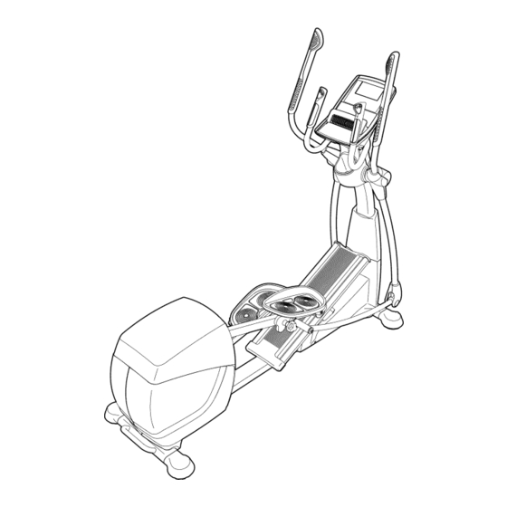
www.nordictrack.com
Model No. NTEL09811.2
Serial No.
Write the serial number in the space
above for reference.
Serial Number Decal
(under frame)
QUESTIONS?
if you have questions, or if parts
are damaged or missing, DO NOT
CONTACT THE STORE; please
contact Customer Care.
iMPORTANT: Please register this
product (see the limited warranty
on the back cover of this manual)
before contacting Customer
Care.
CALL TOLL-FREE:
1-800-TO-BE-FIT
(1-800-862-3348)
Mon.=Fri., 6 a.m.=6 p.m. MT
Sat. 8 a.m.-4 p.m. MT
ON THE WEB:
www.nordictrackservice.com
USE '
AL
Advertisement
Table of Contents
Troubleshooting

Related Manuals for NordicTrack AudioStrider 990 PRO NTEL09811.2


Summary of Contents for NordicTrack AudioStrider 990 PRO NTEL09811.2
- Page 1 Model No. NTEL09811.2 Serial No. USE ' Write the serial number in the space above for reference. Serial Number Decal (under frame) QUESTIONS? if you have questions, or if parts are damaged or missing, DO NOT CONTACT THE STORE; please contact Customer Care.
- Page 2 , Spinning pedals can cause injury. • Reduce pedal speed in a controlled manner. • User weight must not exceed 350 pounds. • Replace label if damaged, illegible, or removed= NORDICTRACK is a registered trademark of ICON IP, Inc.
- Page 3 iMPORTANT PRECAUTIONS WARNING: To reduce the risk ofserious niury, read a llimportant precautions instructions in this manual and all warnings on your elliptical before using your elliptical, iCON assumes no responsibility for personal injury or property damage sustained by or through the use of this product.
- Page 4 BEFORE YOU BEGIN Thank you for selecting the revolutionary reading this manual, please see the front cover of this NORDICTRACK _" AUDIOSTRIDER 990 PRO elliptical. manual. To help us assist you, note the product model The AUDIOSTRIDER 990 PRO elliptical provides an number and serial number before contacting us.
- Page 5 PART iDENTiFiCATiON CHART Use the drawings below to identify the small parts needed for assembly. The number in parentheses below each drawing is the key number of the part, from the PART LIST near the end of this manual. The number following the key number is the quantity needed for assembly.
- Page 6 ASSEMBLY Assembly requires two persons. In addition to the included tool(s), assembly requires the following tools: Place all parts in a cleared area and remove the one Phillips screwdriver packing materials. Do not dispose of the packing materials until you complete all assembly steps. one rubber mallet To identify small parts, see page 5.
- Page 7 Identify the Upright Cover (81). Orient the Upright Cover as shown, and slide it upward onto the Upright (4). Have a second person hold the Upright (4) and the Upright Cover (81) near the Frame (1). Connect the Upper Wire (152) to the Lower Wire (111).
- Page 8 Identify the Right Upper Body Arm (61) and the Right Upper Body Leg (60), which are marked with "Right" stickers, and orient them as shown. Attach the Right Upper Body Arm (61) to the Right Upper Body Leg (60) with three M8 x 43mm Button Bolts (96) and three M8 Jam Nuts (102).
- Page 9 While a second person lifts the back of the Right Pedal Plate (14), insert the Right Pedal Bracket (133) into the Right Pedal Arm (58). Attach the Right Pedal Bracket (133) with an M10 x 20mm Screw (91) and an M10 x 25mm Washer (134).
- Page 10 10. Apply grease to a Short Axle (149) and to two M8 x 22mm Washers (97). Next, tighten an M8 x 23mm Button Screw (82) and an M8 x 22mm Washer (97) a few turns into the Short Axle (149). While a second person holds the front end of the Right Link Arm (59) inside the bracket on the Right Upper Body Leg (60), insert the Short Axle...
- Page 11 12. Orient the Rear Console Cover (80) as shown. Attach the Rear Console Cover (80) to the Upright (4) with four M4 x 16mm Screws (101). 13. While a second person holds the Console (7) near the Upright (4), connect the wires on the Console to the Upper Wire (152) and to the Avoid pinching Right and Left Sensor Wires (108, 110).
- Page 12 14. Attach the Front Console Cover (79) around the Upright (4) by pressing the tabs on the Front Console Cover into the Rear Console Cover (80). 15. See step 5. Tighten the six M8 x 43mm Button Bolts (96). See step 4. Tighten the eight M10 x 20mm Screws (91).
- Page 13 THE CHEST HEART RATE MONITOR HOW TO PUT ON THE HEART RATE MONITOR Do not expose the heart rate monitor to direct sun- light for extended periods of time; do not expose it to The heart rate temperatures above 122 ° F (50 ° C) or below 14 ° F monitor consists of (-10 °...
- Page 14 HOW TO USE THE ELLiPTiCAL HOW TO PLUG iN THE POWER CORD HOW TO MOVE THE ELLiPTiCAL This product must be grounded, if it should malfunc- Due to the size and weight of the elliptical, moving tion or break down, grounding provides a path of least it requires two persons.
- Page 15 HOW TO ADJUST THE POSiTiONS OF THE PEDALS HOW TO EXERCISE ON THE ELLiPTiCAL Each pedal can To mount the elliptical, hold the upper body arms or the be adjusted to handlebars and step onto the pedal that is in the lowest several positions.
- Page 16 CONSOLE DIAGRAM FEATURES OF THE CONSOLE The advanced console offers an array of features designed to make your workouts more effective and enjoyable. When you use the manual mode of the console, you can change the resistance of the pedals and the incline of the ramp with the touch of a button.
- Page 17 HOW TO TURN ON THE POWER HOW TO USE THE MANUAL MODE iMPORTANT: if the elliptical has been exposed to Begin pedaling or press any button on the console to turn on the console. cold temperatures, allow it to warm to room tern= perature before turning on the power, if you do not See HOW TO TURN ON THE POWER at the left.
- Page 18 Follow your progress with the display. Stride--This display mode will show the total num- ber of strides you have pedaled. The display can show the following workout information: Time--When the manual mode is selected, this display mode will show the elapsed time. When a workout is selected, this display mode will show the time remaining in the workout.
- Page 19 When a wireless iFit When your pulse is detected, a heart symbol in will Live module is con- flash in the display each time your heart beats, one nected, the wireless "_ or two dashes will appear, and then your heart rate will be shown.
- Page 20 HOW TO USE A PRESET WORKOUT At the end of each segment of the workout, a series of tones will sound and the next segment of Begin pedaling or press any button on the the profile will begin to flash, if a different resis- console to turn on the console.
- Page 21 HOW TO USE AN IFIT LiVE WORKOUT Select an iFit Live workout. You must have an iFit Live module to use an iFit Live To select an iFit Live workout, press one of the workout. iFit Live buttons. Note: Before some workouts will download, you must go to www.iFit.com and add To purchase an iFit Live module at any time, go to them to your schedule.
- Page 22 Follow your progress with the display. HOW TO CHANGE CONSOLE SETTINGS See step 4 on page 18. The console features a user mode that allows you to view usage information, select a unit of measurement, The My Trail tab will show a map of the trail you are and adjust the contrast level of the display.
- Page 23 Select an audio setting for the voice of the Then, press the Enter button. After a few seconds, personal trainer if desired. the status of the iFit Live module will appear in the display. To exit this display, press and hold down Press the decrease button to view the audio setting the Display button for a few seconds.
- Page 24 MAINTENANCE AND TROUBLESHOOTING Inspect and tighten all parts of the elliptical regularly. First, remove the two indicated M4 x 16mm Screws Replace any worn parts immediately. (101) from the Center Shield (76). Next, using a flat screwdriver, release the tabs on the sides and rear of To clean the elliptical, use a damp cloth and a small the Shield Cover (75).
- Page 25 HOW TO ADJUST THE DRIVE BELT Next, tighten the M8 Nut (122) on the J-bolt (139) one half turn. if you can feel the pedals slip while you are pedaling, even when the resistance is adjusted to the highest setting, the large drive belt may need to be adjusted. To adjust the large drive belt, you must first remove the Shield Cover (75) and the Center Shield (76) (see the instructions below).
- Page 26 EXERCISE GUiDELiNES Burning Fat--To burn fat effectively, you must exer- cise at a low intensity level for a sustained period of time. During the first few minutes of exercise, your body uses carbohydrate calories for energy. Only after the first few minutes of exercise does your body begin to use stored fat calories for energy.
- Page 27 PART LIST Model No. NTEL09811.2 R0911B Key No. Qty. Description Key No. Qty. Description Frame Pedal Arm Roller Rear Stabilizer Tube Ramp Arm Roller Ramp Ramp Arm 16mm Wave Washer Upright M4 x 19mm Screw Axle Cover Front Left Stabilizer Tube Large Arm Bushing Console Large Bearing...
- Page 28 Key No. Qty. Description Key No. Qty. Description M4 x 16mm Screw Small Pulley Snap Ring M8 Jam Nut J-bolt M6 x 16mm Screw Ramp Arm Bushing Power Switch Ramp Arm Clamp M10 Split Washer M10 x 45mm Bolt Shield Mount M10 x 35mm Bolt M4 x 12mm TZP Screw M10 Square Nut...
- Page 29 .146 "U r" 32.- -_ "' 107 _.162 121 "jO 26 121 ¢0 -" :" 43 42 15_I_ 91 F-" 138 1 ' 0.33...
- Page 30 "U r" ¢) 123 ¢ "_. r..o...
- Page 31 "U r" ¢) 101_...
- Page 32 ORDERING REPLACEMENT PARTS To order replacement parts, please see the front cover of this manual. To help us assist you, be prepared to provide the following information when contacting us: • the model number and serial number of the product (see the front cover of this manual) •...
Need help?
Do you have a question about the AudioStrider 990 PRO NTEL09811.2 and is the answer not in the manual?
Questions and answers