Table of Contents
Advertisement
Available languages
Available languages
Operator's
Manua[
[RAFTSMAN°
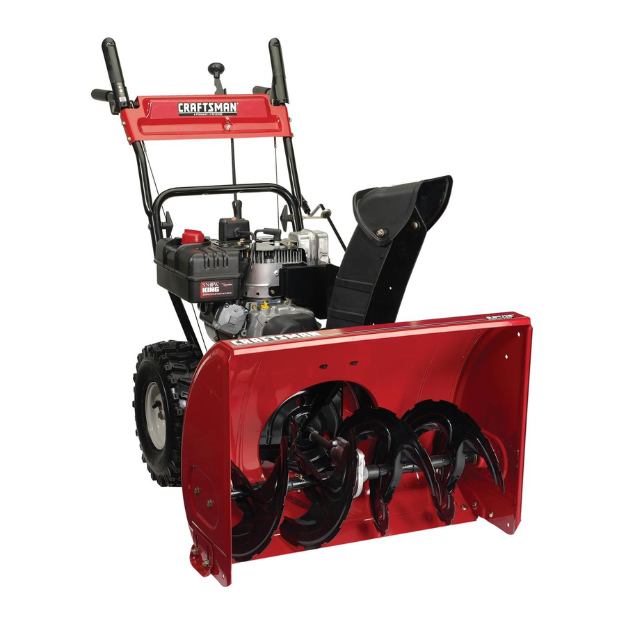
9 Horse Power
SNOW THROWER
Model No. 247.88190
CAUTmON:
Before
using
this product,
read this
manual
and follow
a[[
safety
rules
and operating
_,SAFEW
_,ASSEMBLY
o OPERATION
o MAINTENANCE
o PARTS MST
Sears, Roebuck
and Co., Hoffman
Estates,
[L 60179, U.S.A.
Visit our website:
www, sears,com/craftsman
FORMNO, 769-01909B
07/21/2005
Advertisement
Table of Contents

Related Manuals for Craftsman 247.88190


Summary of Contents for Craftsman 247.88190
- Page 1 _,SAFEW _,ASSEMBLY o OPERATION o MAINTENANCE o PARTS MST CAUTmON: Before using this product, read this manual and follow safety rules and operating Sears, Roebuck and Co., Hoffman Estates, [L 60179, U.S.A. Visit our website: www, sears,com/craftsman FORMNO, 769-01909B 07/21/2005...
- Page 2 Starting/Stopping instructions ....Pages 10-11 Operation ........... Pages 8-12 Two -Year Warranty onCraftsman Snow Thrower For t wo years f rom the date ofpurchase, when t his Craftsman Snow Thrower ismaintained, lubricated and tuned u paccording tothe instructions...
- Page 3 1.KEEPAWAYFROMROTATING IMPELLER ANDAUGER.CONTACT WITHIMPELLER O R AUGER CAN AMPUTATE HANDS ANDFEET, 2. USECLEAN-OUT T OOLTO UNCLOG DISCHARGE C HUTE. 3. DISENGAGE CLUTCH LEVERS, STOP ENGINE, ANDREMAIN BEHIND HANDLES U NTILALL MOVINGPARTS HAVESTOPPED BEFORE UNCLOGGING OR SERVICING MACHINE, 4. TO AVOIDTHROWNOBJECTS INJURIES, NEVER DIRECT D ISCHARGE ATBYSTANDERS.
- Page 4 WARNING: Engine Exhaust, someofitsconstituents, andcertain vehicle components contain or emit chemicals known toState ofCalifornia t ocause cancer a ndbirthdefects orotherreproductive harm. DANGER: Thismachine wasbuilttobeoperated a ccording t otherules forsafeoperation i nthismanual A swithanytype ofpower e quipment, carelessness orerroronthepartoftheoperator canresult i nserious injury. T hismachine is capable ofamputating hands andfeetandthrowing objects.
- Page 5 Operation Maintenance & Storage 1. Do not put hands or feet near rotatingparts, inthe auger/impellerhousing 1. Nevertamperwith safetydevices.Check their properoperationregularly. or chute assembly.Contactwith the rotating partscan amputatehands Referto the maintenance and adjustmentsectionsof this manual. andfeet. 2. Beforecleaning, repairing,or inspectingmachinedisengageall control 2.
- Page 6 ///,' ii!ii!i _i, !_:i!!i!!_ _'_ _ .._. NOTE:Referencesto rightor bft side of the snowthrowerare determined from behindthe unit in the operatingposition(standing directlybehindthesnow thrower,facing the handlepanel), Removing From Carton 1, Cut the cornersof the cartonand lay the sidesfiat on the ground, Removeand discardaIIpackinginserts, 2, Movethe snowthrowerout of the carton, 3, Makecertainthe carton has beencompletelyemptiedbefore...
- Page 7 5, Removetheflat washerand hairpinclip from the end of the chute directionalcontrol insert the end of the chutedirectionalcontrol intothe lowerbracket and securewith the flat washerand hairpinclipiust removed, if necessary', t he lowerbracketcan be adiusted,Referto Chute BracketAdiustment,on Page20, Adjustments Auger Contro_ iMPORTANT: P riorto operatingyoursnow thrower,referto Auger ControlTeston page 12,Readand followall instructionscarefullyand performall adiustmentsto verify yoursnowthroweris operatingsafely and properly,...
- Page 8 Shift Lever Aoger (;antral j(;hute DirectiooaJ (;ontrol (;huteAssemNy Engine Controls Aagers ..SkidShoe Figure 1 Choke Contro_ Operating Controls (See Figure 1) WARNING: Read, understand, and follow all instructions and warnings on the machine and in this manual before operating. The chokecontrolis foundon the rearof theengine and is activated Shift Lever byrotatingthe knobclockwise,Activatingthechoke controlclosesthe...
- Page 9 ignition The ignitionkeyis a safety devise,It mustbe fully insertedin order for the engineto start, Removethe ignitionkeywhenthe snow throweris notin use, Donot turnthe ignitionkey in an attemptto startthe engine,Doingso maycause it to break, C_ean-Out Tool WARNING: Never use your hands to cJear a clogged chute assembly.
- Page 10 Electric Starter Before Starting Engine 1, Determinethat yourhome'swiringis a three-wiregroundedsystem, WARNING:Read, understand, and follow all Ask a licensedelectricianif you are not certain, instructionsand warnings on the machine and in WARNING: The optional electric starter is this manual beforeoperating. equipped with a grounded three-wire power cord and plug, and is designed to operate Theengine wasshippedwith oil in the engine,Checkoil levelbefore on 120 volt AC household current.
- Page 11 Chute C ean-Out TooR 2, Pushthe primertwo or threetimesfor cold enginestart, making sureto covervent hole in the centerof the primerwhenpushing, The chutecleamouttool is conveniently fastenedto the rearof the auger housingwith a mountingclip, Shouldsnowand ice become NOTE: DONOT useprimerto restarta warm engineafter a short lodgedin the chute assemblyduringoperation,proceedasfollowsto shutdown, safelycleanthe chuteassemblyand chuteopening:...
- Page 12 To Engage Augers 1, Toengagethe augersand start throwingsnow,squeezethe auger controlagainstthe left handle,Rebase to stop the augers, Auger ControJ Test Performthe followingtestbeforeoperatingyoursnowthrowerfor the firsttime and at thestart of eachwinter, Checkthe adiustmentof the augercontrol as follows: 1, Whentheauger controlis rebased and in the disengaged"up" position,the eabb shouldhavevery little slack, JtshouldNOT be tight, 2, Jna weBventilatedarea,start the snowthrowerengineas...
- Page 13 Lubrication WARNING: Before Jubricating, repairing, or inspecting, disengage aHcontrols and Si 'i stop engine. Wait until aH moving parts have come to a complete stop. Gear Shaft Thegear (hex)shaft shouldbe lubricatedat leastoncea seasonor after every25 hoursofoperation, 1, Removethe lowerframecover by removingthetwo screwswhich secureit, 2, Applya lightcoatingof an all-weathermulti-purpose greaseto the hexshaft, See Figure3,...
- Page 14 Auger Belt Replacement To removeand replaceyoursnow thrower'sauger belt, proceedas follows: 1, Removetheplasticbelt coveron thefront of the engineby remov- ing the two selfqappingscrews, NOTE:Drainthe gasolinefrom the snowthrower,or placea piece of plasticunderthe gas cap, 2, Carefullypivotthe snowthrowerup and forwardso that it restson the augerhousing,Removethe framecover fromthe underside of the snowthrowerby removingfourself-tappingscrewswhich secureit,...
- Page 15 Augers The augersare securedto the spiralshaftwith two shearpinsand cotter pins.if the augershouldstrikea foreignobject or ice iam, the snow throwerisdesignedso that the pinsmayshear.Referto Figure4. if the augerswill notturn, checkto see if the pinshavesheared. One set of replacement s hearpins has beenprovidedwith the snow thrower.Whenreplacingpins, sprayan oil lubricantintoshaft beforeinsertingnewpins.
- Page 16 Placetheshift leverin thirdForward(F3) position, Drainthe gasolinefrom thesnow thrower,or placea pieceof plasticunderthe gascap, Carefullypivotthe snowthrowerup and forwardso that it restson the augerhousing, 1, a, Removethe frame coverfrom the undersideof the snow thrower by removingfourself-tappingscrewswhich secureit, b, Removethe right-handwheelby removingthe screwand bell washerwhichsecureit to theaxle, 2, Carefullyremovethe hex nutand washerwhichsecuresthe hex shaftto the snow throwerframe and lightlytap the shaft'send to...
- Page 17 Checking Engine Oil Oil FillCap_I 1. Be sureengine is uprightand level 2. Unscrewoil fill capfrom oil fillertube and wipedipstickclean. See Figure7. 3. Screwoil fill cap backinto oil filler tube.Tightensecurely. 4. Unscrewand removeoil fill cap from oil filler tube. Noteoil level If oil readingon dipstickis below"ADD"mark,slowlyaddoil to reach "FULl"...
- Page 18 Checking Spark PRug Checksparkplug yearlyor every 100operatinghours 1, Cleanareaaroundspark plug, 2, Removeand inspectspark plug, 3, Replacespark plug if porcelainiscrackedor if electrodesare: Pitted,burnedor fouledwith deposits 4, Checkelectrodegap with a feelergaugeand set gap to ,030 (O,76mm) i f necessary,See Figure8, 5, Reinstallspark plugand tightensecurely, 1..030 (.76 ram) Gap 2.
- Page 19 Auger Control Adjustment Referto AugerControlTeston Page12 to adiustthe augercontrol Drive Control Adjustment WARNING: Never attempt to make any adjustments while the engine is running, except where specified in this operator's manual When thedrive controlis releasedand in the disengaged"up"position, the cabb shouldhavevery littb slack,It shouldNOTbe tight, Checkthe adiustmentof the drivecontrolas fo[bws: 1, With thedrive controlreleased,pushthe snowthrowergently forward,The unitshouldroll freely,...
- Page 20 Skid Shoe Adjustment Thespace betweenthe skid shoesand thegroundcan be adiusted, Forclose snow removalon a smoothsurface,raiseskid shoeson the augerhousing, Forsnow removalon a roughsurfacesuch as a graveldriveway, lowerthe skid shoeson the auger housing. Toadiustthe skid shoes: 1. Race a blockof wood (2 x 4) beneaththe shave plateto temporarilyraisethe snowthrower'saugerhousingoff the ground.
- Page 21 --.,, Toavoidengine problems,the fuel systemshouldbe emptiedbefore storagefor 30 days or longer,Followtheseinstructionsto prepareyour Carburetor snow throwerfor storage: container outdoors, away from any open WARNING: Drain fuel into an approved flame. Be certain engine is cool. Do not engine during smoke. Fuel left in warm weather deteriorates and will cause serious...
- Page 22 Problem Remedy Cause 1, Movechokebver to OFF position, 1, Unit runningon CHOKE, Engine runs erratic 2, Cban fuel line; fill tank with clean, 2, Blockedfuel line or stab fuel fresh gasoline, 3, Drainfueltank, Refillwith fresh fuel 3, Wateror dirt in fuel system, 4, Contact SearsParts&...
- Page 25 Craftsman 9 HP Snow Thrower Model 247.88190 731-2635 SnowRemoval T oolMount 29, 684-04107 SpiralAssembly,LH 684-04057 ImpellerAssembly,12"Dia, 30, 684-04108 SpiralAssembly,RH 710-0347 Hex Screw,3/8-16,1,75,Gr5 31, 731-04870 Spacer,1,25OD x ,75 ID x 1,00 710-0451 Bolt,Carriage,5/16-18,,750Grl 32, 736-0188 Washer,Flat, ,76x 1,49x ,06 710-0604A Screw, 5/16-18,0,625...
- Page 27 Craftsman 9 HP Snow Thrower Model 247.88190 631-04133 HandleAssembly,ClutchLock,LH 27, 731-04869 Chute,FlangeKeeper 631-04134A HandleAssembly,ClutchLock,RH 28, 746-04228 CaNe,SpeedSelector 684-04105A HandleAssembly,Engagement L H 29, 746-0605 Houlder,CaNe Barrel,LH 684-04106A HandleAssembly,Engagement R H 30, 747-04263 EyeBolt, ChuteCrank 31, 790-00202 Shift Lever 710-0224 Screw,#10-16,0,500 710-04326...
- Page 29 Craftsman 9 HP Snow Thrower Model 247.88190 756-04177 Disc, FrictionWheel 37, 731-04873 Spacer,1,25x ,75x 3,0 684-04153 FrictionWheelAssembly,5,50D 38, 738-04168 Axle, ,75x 22" 684-04154 SupportBracketAss'y,FrictionWheel 39, 741-0919 Ball Bearing 684-04156 Shift Assembly,Rod 40, 710-0106 Hex Screw,1/4-20,1,25,Gr5 710-0627 Hex Screw,5/16-24,,750,Gr5, Lock 41, 710-0191...
- Page 30 Tecumseh 9 H.P. Engine LH318SA-156554 Craftsman Snow Thrower Model 247.88190 >300 0_',- 0>291 370K...
- Page 31 Tecumseh 9 H.P. Engine LH318SA-156554 Craftsman Snow Thrower Model 247.88190 Ref.No. Part No. Ref. No. Part No. Description Description 35385 651080 Washer Cylinder 27652 DowelPin 37588 GovernorGear Ass'y,(Incl,81) 650820 30588A Screw,1/4-20x 0,5" GovernorSpool 30969 29193 ExtensionCap RetainingRing 28277 Washer 650833 Screw,1/4-20x 1-3/16"...
- Page 32 Tecumseh 9 H.P. Engine LH318SA-156554 Craftsman Snow Thrower Model 247.88190 Ref. No. Part No. Description Ref. No. Part No. Description 184, 33263 CarburetorTo intakePipeGasket 301, 35355 FuelCap 185, 33877 intakePipe 311, 35942 Oil FillPlug 186, 34667 GovernorLink 314, 650873 Screw,1/4-20x 3/4"...
- Page 33 Tecumseh 9 H.P. Engine LH318SA-156554 Craftsman Snow Thrower Model 247.88190 Ref. No. Part No. Description 640052 Carburetor 631776A ThrottleShaft & LeverAssembly 631970 ThrottleReturnSpring 631778 ThrottleShutter 650506 ShutterScrew 632112 Choke Shaft& LeverAssembly 632174 Choke Shutter 630735 Choke Positioning Spring 632184 FuelFitting...
- Page 34 Tecumseh 9 H.P. Engine LH318SA-156554 Craftsman Snow Thrower Model 247.88190 Ref. No. Part No. Description 590749 RewindStarter 590599A SpringPin (IncL 4) 590600 Washer 590679 Retainer 590601 Washer 590678 BrakeSpring 590680 StarterDog 590412 DogSpring 590682 Pulby & RewindSpringAssembly 590750A StarterHousingAssembly 590535 StarterRope(Length98"x 9/64"...
- Page 35 Tecumseh 9 H.P. Engine LH318SA-156554 Craftsman Snow Thrower Model 247.88190 Ref. No. Part No. Description 33329E ElectricStarter110Volt (optional) 33451 DustCover 33842 RetainerRing 33430 SpringRetainer 33431 Anti-DriftSpring 37050 Gear & Nut (IncL2) 35449 Drive EndCap Assembly 35450 "0" Ring 35915 Armature...
- Page 36 MSTADO DE PIEZAS PRECAUCION: antes de utimizar este producto, mea este manual y siga todas mas regmas de seguridad y _as instrucciones funcionamiento, Sears, Roebuck and Co., Hoffman Estates, IL 60179, U.S.A. Visite nuestro sitio web: www.sears.corn/craftsman NO de FORMULARIO 769-01909 06/08/2005...
- Page 37 ..............posterior Garantia de dos mios para la m_quina quitanbve Craftsman Durantedos ahosa partirde la fechade compra,siempreque a esta m&quina quitanievese le realbe el servbio de mantenimbnto,lubricaci6n y puestaa puntode acuerdoa las instrucciones del manualdel propietario,SearsrepararA sin cargocualqubr defectode materiabso manode obra.Siesta mAquina quitanbve Craftsmanse utiliza paraprop6sitoscomerciabs o de alquiler,esta garanfiase aplicas61o durante30 diasa...
- Page 38 1.KEEPAWAYFROMROTATING IMPELLER ANDAUGER.CONTACT WITHIMPELLER O R AUGER CAN AMPUTATE HANDS ANDFEET, 2. USECLEAN-OUT T OOLTO UNCLOG DISCHARGE C HUTE. 3. DISENGAGE CLUTCH LEVERS, STOP ENGINE, ANDREMAIN BEHIND HANDLES U NTILALL MOVINGPARTS HAVESTOPPED BEFORE UNCLOGGING OR SERVICING MACHINE, 4. TO AVOIDTHROWNOBJECTS INJURIES, NEVER DIRECT D ISCHARGE ATBYSTANDERS.
- Page 39 ADVERTENCIA: elescape delmotor d eesteproducto, algunos d esuscomponentes y algunos c om- ponentes d elvehiculo c ontienen o emiten productos quimicos q ueelestado deCalifornia c onsidera q ue pueden producir cancer, defectos d enacimiento u otros problemas r eproductivos. PELIGRO: Estamaquina e stadiseSada p araserutilizada respetando lasreglas deseguridad c ontenidas enestemanual AIigual q ueconcualquier ripedeequipo el6ctrico, undescuido o errordepartedeloperador puede producir lesiones graves.
- Page 40 Operaci6n Mantenimiento y alrnacenamiento 1. Nuncamanipulelosdispositivosde seguridadde manera imprudente. 1. No pongalasmanes o los piescerca de las piezas rotatorias,en la caja Controleperiodicamente que funcionende forms adecuada.RemRase a de la barrena/ motoro en el montajedel canal de descarga.El contacto las seccionesde mantenimientoy ajustede este manual. con las piezas rotatoriaspuedeproducirla amputaci6nde manosy pies.
- Page 41 ,._, NOTA:las referenciasal ladoderechoo y ciertosde lamb, q uina quitanievesedeterminandesdela parteposteriorde la unidaden posici6nde operaci6n(permaneciendo directamente detrAsde la m_quinaquitanieve,mirandohaciael panelde la maniia), Extracci6n de la unidad de la caja 1, Corte lasesquinasde la caiade cart6ny exti6ndaIaen el piso Quitey descartetodos los insertosde empaque, 2, Saquela m_quinaquitanievede la caia, 3, AsegOrese de vaciarcompIetamente la cajaantesde tirarIa Partes sueltas...
- Page 42 5. Quitela arandelaplana y el brochede horquilladel extremodel controldireccionaldel canal Inserteel extremodelcontroldireccional del canalenel soporteinferior y asegOrelo m ediante la arandela planay el brochede horquilla que acabade retirar. S ies necesario, puedeaiustarse el soporteinferior. Consulte "Aiuste del soporte delcanal"en la p_,gina 20. Ajustes Contro_ de _a barrena IMPORTANTE: antesde operarsu mAquinaquitanieve,consultela...
- Page 43 Figura 1 Contro_ de obturaci6n Contro es de operaci n (Vea la Figura 1) ADVERTENCIA:lea,comprenda y siga todas las instmceiones y advertencias que apareeen en ta m_quinay en este manual antes de operarla. El controlde obturaci6nse encuentraen la parteposteriordel motor, y se activahaciendogirar la perillaen sentidode lasaguiasdel reloi, Pa_anca de cambios AI activarel controlde obturacbn se cierrala placa de obturaci6ndel...
- Page 44 Contro_ de la barrena LJave de encendido La Ilavede encendidoes un dispositivode seguridad,Debeestar completamente insertadaparaque el motorarranque,Retirela Ilave de encendidocuandono usela m_quinaquitanieve, Nogire la Ilavede encendidopara intentararrancarel motor,AI hacerlopodrh romperla, Herramienta de Hmpieza ADVERTENCIA: nunca use sus manos para Jiberar un montaje de canal tapado. Antes destaparlo, apague el motor y permane°...
- Page 45 Arrancador e!_ctrico Antes de encender el motor 1, Determine s[elcableado d esuhogar esunsistema d etres cab#sconectado a ADVERTENCIA:lea, comprenda y siga todas las t_e_a, Consulte c onunelectidsta matriculado sinoestb, seguro, instrucciones y advertencias que aparecenen la ADVERTENCIA: el arrancador el_ctrico m_quina yen este manual antes de operarla.
- Page 46 Arrancador de retroceso 6, Limpiela nievey la humedaddel _reaalrededordel motor,as[ 1, Gire el controlde obturaei6na posici6nde obturaci6nFULL como tambi6nen el _rea (y alrededorde esta) del interiorde los (encendidocon el motoren if[o), controbs de la transmisi6ny de la barrena,Asimismo,engancbey suelte amboscontrolesvariasveces, NOTA:Is[ el motorya estAcaliente,ubique el controldel obturadoren Arrancador de retroceso...
- Page 47 NOTA:al seleccionarunavelocidadde la transmisi6n,use lasveloci- 8. Ubiquela mensulahaciaarriba parabrindar mAsiuego (o hacia dadesm_s lentashastaque se sienta c6modoy se hayafamiliarizado abaio para aumentarla tensi6ndel cable). Vea la figura2. conel funcionamiento de la m_quinaquitanieve. 9. Vuelvaa apretarla tuerca hexagonal s uperior. 10.Repitala prueba de controJ de ta barrena para verificar 2.
- Page 48 Lubricaci6n ADVI RTENCiA: antes de reatizar tareas de Jubricaci6n, reparaci6n o inspecci6n, desengrane tedes Si 'i los controles y detenga et motor. Espere a que se detengan tedas las piezas rnSviles. Eje de engranaje El eie de engranaie(hexagonal) s e debe lubricaral menosuna vez por temporadao tras cada25 horasde operaci6n.
- Page 49 Reemplazo de la correa de la barrena Para retirary reemplazarla correade la barrenade su m_quina quitanieve,procedacomose indicaa continuaci6n: 1, Saquela cubiertapl_sticade la correa ubicadaen el frentedel motor,Paraello saquelosdos tornillosautorroscantes, NOTA:drenela gasolinade la mb, q uinaquitanieveo coloqueun trozo de plAsticodebaiodel tap6nde Ilenadodel combustible, 2, Gire concuidadolamb, q uinaquitanievehaciaarribay hacia delantede maneraque quedeapoyadasobrela cajade la barrena, Saquela cubiertadel marcodesdedebaiode la mAquina quita-...
- Page 50 _arrenas Las barrenas est_naiustadasal eieespiralcon dospasadores de cuchillay pasadores de chaveta. S i la barrenagolpeaun obieto extrahoo una barrade hielo,la ma'quina q uitanieve estb,disehadade maneraque lospasadores sepuedencortar.Consultela figura4. Si las barrenasno giran,verifiquesi los pasadoressecortaron. Junto con la m_quinaquitanievese incluyeun iuego de pasadores de cuchillade repuesto.Cuandoreemplacelos pasadores,rode un lubricantede aceite dentrodel eje antesde colocarlos nuevos pasadores.
- Page 51 Coloquela palanca de cambiosen la tercera posici6n de avance (F3), Drenela gasolinade lamb, q uinaquitanieveo coloqueun trozo de pl£sticodebaiodel tap6nde Ilenadodel combustible, • Gire concuidadola m_quinaquitanievehaciaarribay hacia delantede maneraque quedeapoyadasobrela cajade la barrena, 1, a, Saquela cubierta del marcodesdedebaiode la m£quina quitanieve retirando loscuatrotornillos autorroscantes que la aseguran, b, Retirela ruedaderechaquitandoel tornilloy la arandelade campanaque la aseguranal eie,...
- Page 52 Contro_ de_ aceite tier motor Tap6nde Ilenadode aceite 1, AsegOrese de que el motorest_ verticaly nivelado 2, Desenrosque el tap6nde Ilenadode aceitedel tubode Ilenadode aeeitey limpiela varillade nivelde aeeite,Veala figura7, 3, Vuelvaa enroscarel tap6nde Ilenadode aceiteen el tubo de Ilenadode aeeite,Aiustebien, 4, Desenrosque y retireel tap6nde Ilenadode aceite del tubode Ilenadode aceite,Fiieseen el nivelde aceite,Si la lecturaen la varilladel nivelde aceite estb,por deba}ode la marca"ADD"...
- Page 53 ControR de bujia Controlela buiia anualmente o cada tO0 horasde operaci6n, 1, Limpieel _rea alrededorde la buiia, 2, Saquee inspeccionela buiia, 3, Cambiela buiiasi la poreelanaest_ rotao si loselectrodosest&n: picados,quemadoso atoradoscon dep6sitos 4, Controleel espaciodel electrodocon un calibradorde separacio- nesy aiustedichoespaeioa 0,030pulg (0,76ram)si es necesario, Vea la figura8, 5, Vuelvaa instalarla buiiay aiustebien, 1.
- Page 54 Ajuste de[ control de [a barrena Consultela pruebade controlde la barrenaen [ap_gina 12para ajustardichocontrol, Ajuste de control de [a transmis[Sn ADVERTENC[A: NUNCA intente reaJizar encendido, excepto si se especifica asi en ning_n tipo de ajuste mientras e[ motor est_ este manual de[ operador. Cuandose suelta e[controlde la transmisi6ny est_ en posici6n desenganchada ardba,el cabledebetener muypocojuego, NOdebe estartenso,...
- Page 55 Ajuste de la zapata antidestizante Se puede aiustarel espacioque existeentrela zapata antideslizante y el suelo, Yea la figura 11, Si deseaquitarnieveal ras del suelo,elevem_s laszapatas antideslizantes en la caiade la barrena, Use las posicionesmediao baia cuandola superficieque desee limpiarsea despareia,como un caminode grava, Paraaiustar laszapatasantideslizantes: 1, Afloielas cuatrostuercashexagonales (dosen cada lado)y los pernosdel carro,Muevalas zapatasantideslizantes a la posici6n...
- Page 56 ---,, Paraevitarproblemascon el motor,el sistemadel combustible debe ser vaciadoantesde almacenarlamb, q uina durante30 dhs o m_s, Carburador Sigaestas instruccionesparaprepararsu m_,quina quitanievepara almacenarla: ADVERTENCIA: drene et combustible dentro de un reeipiente aprobado en un lugar exterior, lejos de todo tipo de fuego. Compruebe que el motor est_ fdo.
- Page 57 Probiema Remedio Causa E motor no arranoa 1. Lapalancadeobturaci6nnoest6. enla Pongalapalancadeobturaci6nenla posicbnON(encendjdo). posicJ6n ON(encendido), 2,Sehadesconectado elCable d eh bujfal 2. Conecte el Cable a la bujial 3, E!tanque deCombustible est_vacio0 el 3. Uene eltanque Con gasolJna limpia y fresca, c°mbust_b!e esvae/O' 4.
- Page 60 iiiiiiiiiiiiiiiiiiiiiiiiii?ii_ ..Your Home iiiiiiiiiiiiii_,_, iiiiiiiiiiiiii iiiiiiiiiiiiii For repair-in your home-of all major brand appliances, iiiiiiiiiiiiii lawn and garden equipment, or heating and cooling systems, iiiiiiiiiiiiii iiiiiiiiiiiiii no matter who m ade .. no matter who o,d it, iiiiiiiiiiiiii iiiiiiiiiiiiii iiiiiiiiiiiiiiiiii iiiiiiiiiiiiii For the replacement...
Need help?
Do you have a question about the 247.88190 and is the answer not in the manual?
Questions and answers
How to make one tire drive. Right now, both tires drive.