Table of Contents
Advertisement
Quick Links
Extron Electronics, Europe
Extron Electronics, USA
Beeldschermweg 6C, 3821 AH Amersfoort
1230 South Lewis Street, Anaheim, CA 92805
800.633.9876 714.491.1500 FAX 714.491.1517
+31.33.453.4040 FAX +31.33.453.4050
USA
The Netherlands
Extron Electronics, Asia
Extron Electronics Information
135 Joo Seng Rd. #04-01, PM Industrial Bldg.
ExtronWEB
: www.extron.com
™
+65.383.4400 FAX +65.383.4664
ExtronFAX
™
: 714.491.0192
Singapore 368363
24-hour access—worldwide!
User's Manual
P/2 DA2 WM/EC and AAP models
Distribution Amplifier
68-463-01
Printed in the USA
Advertisement
Table of Contents

Related Manuals for Extron electronics APP


Summary of Contents for Extron electronics APP
- Page 1 Extron Electronics, Europe Extron Electronics, Asia Extron Electronics, USA Beeldschermweg 6C, 3821 AH Amersfoort 135 Joo Seng Rd. #04-01, PM Industrial Bldg. 1230 South Lewis Street, Anaheim, CA 92805 800.633.9876 714.491.1500 FAX 714.491.1517 +31.33.453.4040 FAX +31.33.453.4050 +65.383.4400 FAX +65.383.4664 The Netherlands Singapore 368363 User’s Manual P/2 DA2 WM/EC and AAP models...
-
Page 2: Fcc Class A Notice
Precautions Safety Instructions • English Warning This symbol is intended to alert the user of important Power sources • This equipment should be operated only from the power source indicated on the product. This equipment is intended to be used with a main operating and maintenance (servicing) instructions power system with a grounded (neutral) conductor. -
Page 3: Table Of Contents
Table of Contents Chapter 1 • Introduction ... 1-1 About the P/2 DA2 WM/EC and P/2 DA2 WM/EC AAP ... 1-2 Features ... 1-2 Chapter 2 • Controls and Installation Front and Rear Panels ... Front faceplate ... 2-2 Rear connectors ... 2-3 Installing the P/2 DA2 WM/EC ... -
Page 4: Chapter 1 • Introduction
P/2 DA2 WM/EC Chapter One Introduction About the P/2 DA2 WM/EC and P/2 DA2 WM/EC AAP Features P/2 DA2 WM/EC Table of Contents P/2 DA2 WM/EC Table of Contents... -
Page 5: P/2 Da2 Wm/Ec
Introduction About the P/2 DA2 WM/EC and P/2 DA2 WM/EC AAP The P/2 DA2 WM/EC and P/2 DA2 WM/EC AAP are a one input, two output, high resolution VGA/XGA distribution amplifier with audio. With a video bandwidth of 300 MHz, this distribution amplifier is compatible with VGA, SVGA, VESA, XGA, and SXGA graphics cards, monitors, projectors, and LCD panels. -
Page 6: Front And Rear Panels
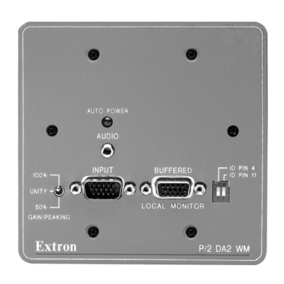
Controls and Installation Front and Rear Panels Front faceplate AUTO POWER 100% UNITY GAIN/PEAKING Figure 2-1 — P/2 DA2 WM faceplate features Both WM and EC models have the same front and rear panel connectors and features. See figure 2-2. 2-color power/signal LED —... -
Page 7: Installing The P/2 Da2 Wm/Ec
Controls and Installation, cont’d Installing the P/2 DA2 WM/EC Easy setup procedure The wall-mounted P/2 DA2 WM kit consists of the faceplate/distribution amplifier assembly and a mounting bracket which mounts in a wall opening and to which the faceplate assembly is attached. The P/2 DA2 EC kit consists of the faceplate/distribution amplifier assembly which mounts in the Euro Channel raceway. -
Page 8: Cabling
Controls and Installation, cont’d Cabling The P/2 DA2 WM cabling diagram below shows how to connect input and output devices to the distribution amplifier ’s front panel. The P/2 DA2 EC model has identical connectors. AUTO POWER 100% UNITY GAIN/PEAKING Figure 2-5 —... -
Page 9: Installing Architectural Adapter Plates
Controls and Installation, cont’d Figure 2-6 — Fastening captive screws Slide the audio cable connector into the audio output connector on the interface. Balanced audio To attach the interface to a balanced audio system, do the following: Attach the audio cable to a balanced speaker input connector (tip, ring, and sleeve). -
Page 10: P/2 Da2 Wm Wallmount Installation
Controls and Installation, cont’d P/2 DA2 WM wallmount installation Once the input and output cables have been connected and the P/2 DA2 WM has been successfully tested, the faceplate may be attached to the mounting bracket using the 4 supplied screws. See figure 2-8. The center pole of the power input connector contains no conductor. -
Page 11: Appendix
Controls and Installation, cont’d OFF — Set both pins to Off if you are attaching a local monitor to the P/2 DA2 WM/EC. P/2 DA2 WM/EC Appendix Specifications Faceplate Dimensions Cables Architectural Adapter Plates Mounting Templates P/2 DA2 WM/EC Controls and Installation 2-12 P/2 DA2 WM/EC Operation... - Page 12 Appendix P/2 DA2 WM/EC Specifications Video input Number/signal type ... 1 VGA/SVGA/XGA/SXGA RGBHV, RGBS, RGsB, RsGsBs Connectors ... 1 15-pin HD male Nominal level(s) ... Analog ... 0.7V p-p Minimum/maximum level(s) ... Analog ... 0.4V to 2.0V p-p with no offset Impedance ...
-
Page 13: P/2 Da2 Wm Faceplate Dimensions
Appendix, cont’d P/2 DA2 WM Faceplate Dimensions Dimensions of the P/2 DA2 WM and its AAP version are provided here for those who wish to make their own customized faceplate. The following diagrams are not drawn to scale. HAND SAND TO 0.06" RADIUS AROUND THE TOP OF THESE EDGES. -
Page 14: Cables
Appendix, cont’d Cables The table below lists various lengths of high resolution VGA cables which can be used with the P/2 DA2 WM/EC. Male-to-female VGA cables VGA 6’ HR VGA 3’ HR A (with audio) VGA 6’ HR A (with audio) VGA 12’... - Page 15 ¼ " ¼ " . a . . a . . a . . a . ¼ " ¼ "...
-
Page 16: P/2 Da2 Wm Mounting Template
Appendix, cont’d P/2 DA2 WM/EC Appendix A-10 P/2 DA2 WM Mounting Template Use this template as a guide for cutting the hole in the installation surface (wall or furniture). This diagram is shown at actual size. The light gray area represents where the P/2 DA2 WM enclosure (2.562”... - Page 17 The solid, outer line (4.50” H x8.325” W) represents the outside edge of the wall mounting bracket. The dashed line indicates the recommended cut-out area (3.875” H x 7.525” W) for the installation surface.
Need help?
Do you have a question about the APP and is the answer not in the manual?
Questions and answers