Table of Contents
Advertisement
Quick Links
Extron Electronics, USA
Extron Electronics, Europe
1230 South Lewis Street
Beeldschermweg 6C
Anaheim, CA 92805
3821 AH Amersfoort
USA
The Netherlands
714.491.1500
+31.33.453.4040
www.extron.com
Fax 714.491.1517
Fax +31.33.453.4050
© 2006 Extron Electronics. All rights reserved.
Extron Electronics, Asia
Extron Electronics, Japan
135 Joo Seng Road, #04-01
Kyodo Building
PM Industrial Building
16 Ichibancho
Singapore 368363
Chiyoda-ku, Tokyo 102-0082 Japan
+65.6383.4400
+81.3.3511.7655
Fax +65.6383.4664
Fax +81.3.3511.7656
User's Manual
RGB 170
Computer Video Interface
68-1189-01 A
07 06
Advertisement
Table of Contents

Subscribe to Our Youtube Channel
Summary of Contents for Extron electronics RGB 170
- Page 1 Anaheim, CA 92805 3821 AH Amersfoort PM Industrial Building 16 Ichibancho The Netherlands Singapore 368363 Chiyoda-ku, Tokyo 102-0082 Japan 07 06 714.491.1500 +31.33.453.4040 +65.6383.4400 +81.3.3511.7655 www.extron.com Fax 714.491.1517 Fax +31.33.453.4050 Fax +65.6383.4664 Fax +81.3.3511.7656 © 2006 Extron Electronics. All rights reserved.
- Page 2 Protección del cables de alimentación • Los cables de alimentación eléctrica se deben protección aislante, que puedan encontrarse dentro use. In no event will Extron Electronics be liable for direct, indirect, or consequential instalar en lugares donde no sean pisados ni apretados por objetos que se puedan de la caja o alojamiento del producto, y que puedan apoyar sobre ellos.
- Page 3 • • • • • • • • • • • • • • • • • • • • • •...
-
Page 4: Table Of Contents
Appendix A • Specifi cations, Part Numbers, and Accessories ..................A-1 Specifi cations ................A-2 Parts ....................A-4 All trademarks mentioned in this manual are the properties of their respective owners. 68-1189-01 A 07 06 RGB 170 Computer Video Interface • Table of Contents... -
Page 5: Chapter One • Introduction
Table of Contents, cont’d RGB 170 Chapter One Introduction About this Manual About the RGB 170 Features RGB 170 Computer Video Interface • Table of Contents... -
Page 6: About This Manual
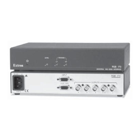
The unit restores the sync signals, but does not process them for format, polarity, or delay. Chapter Two The RGB 170 is housed in a 1U, half rack, 6" deep, 2-piece enclosure, and uses an internal power supply. Features Bandwidth —... -
Page 7: Installation Overview
Mounting the RGB 170 below. For optional rack mounting, do not install the rubber feet. Mount the RGB 170 on a half-rack width, 6" deep, 1U high rack Cable the inputs and outputs to the RGB 170. See Cabling shelf (Extron part #60-190-10 or 60-604-10) or a standard 19-inch on page 2-7. -
Page 8: Under-Desk Mounting
Faceplate or inside (concealed side) of the furniture, where the interface will be located. Through-desk mounting Mount the RGB 170 through a desk or table, using the optional mounting kit (part #70-077-02), as illustrated below. Front false faceplate uses 2 screws. -
Page 9: Front Panel Features
PEAKING GAIN The output of the RGB 170 is on BNC connectors. If the display RGB 170 UNIVERSAL VGA-QXGA INTERFACE uses a 15-pin HD connector, use an Extron SYM BNCM cable (Extron part #26-533-xx) to make the connection. - Page 10 Up to 185 m. MHR or 300 m. RG6 cable IN P (1600 x 1200 signal) O P- Extron RGB 170 VGA-QXGA Interface Projector Chapter Three Adjusting the Display Signal Compatibility Potentiometer Adjustments RGB 170 Computer Video Interface • Installation, Operation...
-
Page 11: Signal Compatibility
Potentiometer Adjustments gradations of color. Use the illustration below as a guide. The RGB 170 achieves its superior amplifi cation by using two independent peaking potentiometers: LF for streaking adjustment and HF for detail adjustment. The goal in adjusting the RGB 170’s Gain and Peaking potentiometers is to produce a sharp image (i.e., an image free... - Page 12 The potentiometer should be adjusted between these two and Accessories extremes. Alternate between adjusting the HF and LF potentiometers until the display shows a clear and sharp image. Specifi cations Parts RGB 170 Computer Video Interface • Adjusting the Display...
-
Page 13: Appendix A • Specifi Cations, Part Numbers, And Accessories
Sync All nominal levels are at ±10%. Input type ........RGBHV, RGBS, RGsB, RsGsBs Specifi cations are subject to change without notice. RGB 170 • Specifi cations, Part Numbers, and Accessories RGB 170 • Specifi cations, Part Numbers, and Accessories... -
Page 14: Parts
M59-5 BNC 3', 6', 12', 25', 35', 50', 75', 100' 26-499-xx RG6-5 BNC 3', 6', 12', 25', 35', 50', 75', 100' 26-369-xx SYM BNCM 6'', 1', 3', 6', 12', 25', 50', 75', 100' 26-533-xx RGB 170 • Specifi cations, Part Numbers, and Accessories...


Need help?
Do you have a question about the RGB 170 and is the answer not in the manual?
Questions and answers