Advertisement
Available languages
Available languages
Quick Links
12"(305ram)
Compound
Laser
Miter S aw
Sierra
ingletadora
compuesta con
I;iser de305mm
(12pulg)
Scie coulissante
o.n.glets
mixtes
systeme laser,
305mm (12po)
A16276 - 01-13-00
Copyright © 2006DeltaMachinery
Instruction Manual
Manuel d 'Utilisation
Manual d eInstrucciones
www.deltamachinery.com
(800)223-7278- US
(800)463-3582 - CANADA
Advertisement

Related Manuals for Delta 36-322L


Summary of Contents for Delta 36-322L
- Page 1 12"(305ram) Compound Laser Miter S aw Sierra ingletadora compuesta con I;iser de305mm (12pulg) Scie coulissante o.n.glets mixtes systeme laser, 305mm (12po) Instruction Manual Manuel d 'Utilisation Manual d eInstrucciones www.deltamachinery.com (800)223-7278- US A16276 - 01-13-00 (800)463-3582 - CANADA Copyright © 2006DeltaMachinery...
-
Page 2: Table Of Contents
There are certain applications for which tools and equipment are designed. Delta Machinery strongly recommends that this product NOT be modified and/or used for any application other than for which it was designed. If you have any questions relative to its application DO NOT use the product until you have contacted Delta Machinery andwe have advised you. - Page 3 It is important for you to read and understand this manual• The information it contains relates to protecting YOUR SAFETY and PREVENTING PROBLEMS• The symbols below are used to help you recognize this information• Indicates an imminently hazardous situation which, if not avoided, will result in death or serious injury. Indicates a potentially hazardous situation which, if not avoided, could result in death or serious injury.
- Page 4 "OFF" position. An accidental start- A guard or any other part that is damaged should be up can cause injury. properly repaired or replaced with Delta or factory 22. MAKE YOUR WORKSHOP...
- Page 5 Failure to follow these rules may result in serious personal injury. OPERATE THIS MACHINE until it is other clamps prior to operation. Loose clamps completely assembled and installed according to the cause parts or the workpiece to be thrown at high instructions.
- Page 6 LASER LIGHT - DO NOT STARE INTO BEAM, APERTURE, or into a reflection from a mirror-like surface. DO NOT USE OPTICAL TOOLS SUCH AS A TELESCOPE OR TRANSIT TO VIEW THE LASER BEAM. Serious eye injury could result. DO NOT OPERATE THE LASER AROUND CHILDREN or allow children to operate the laser. Serious eye injury may result.
- Page 7 POWER CONNECTIONS A separate electrical circuit should be used for your machines. This circuit should not be less than #12 wire and should be protected with a 20 Amp time lag fuse. If an extension cord is used, use only 3-wire extension cords which have 3-prong grounding type plugs and matching receptacle which will accept the machine's plug.
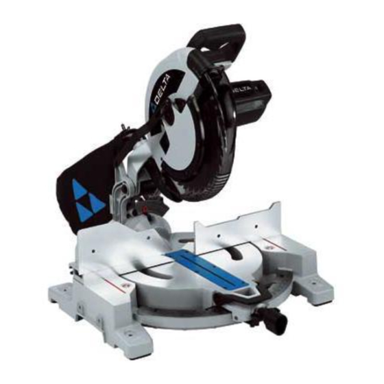
- Page 8 FOREWORD Delta Model 36-322L is a high capacity 12" single-bevel compound miter saw equipped with a laser guide and designed to cut wood and non-ferrous metals. This machine is supplied with design features that increase the cutting capacity. This machine can cut 6" base moulding mounted verLically, crosscut 2" x 8" dimensional lumber, miter 2" x 6" dimensional lumber at 45 °...
-
Page 9: Assembly
YOUR OWN SAFETY, DO NOT CONNECT THE MACHINE TO THE POWER SOURCE UNTIL THE MACHINE IS COMPLETELY ASSEMBLED AND YOU READ AND UNDERSTAND THE ENTIRE INSTRUCTION MANUAL. ASSEMBLY TOOLS REQUIRED Wrench (Supplied) 2mm Hex Wrench (Supplied) Open-end 7/16" Wrench (Supplied) ASSEMBLY TIME ESTIMATE Assembly for this machine takes less than 30 minutes. -
Page 10: Operation
FENCE OPERATION DISCONNECT MACHINE FROM POWER SOURCE. The saw is equipped with two fences. The fence that is shipped bolted to the table should remain and needs no adjusting. The other fence piece (A) Fig. 7 is adjustable and should be placed as close to the blade as possible for all bevel or straight cuts to provide adequate support and for an accurate cut. - Page 11 ROTATING THE TABLE FOR MITER CUTTING The compound miter saw will cut any angle from a straight 0 ° cut to 48 ° right and left. To adjust, place locking knob (A) in the unlocked position as shown in Fig. 11. Then push down on lock lever (B) while turning the table to the desired position. After moving the saw, place knob (A) in the locked position by twisting it clockwise until it stops.
- Page 12 TABLE HAZARD ZONE _THE AREA INSIDE LINES (A) FIG. 17 ON THE TABLE IS DESIGNATED AS A HAZARD ZONE. NEVER PLACE YOUR HAND(S) INSIDE "TABLE HAZARD ZONE" (WITHIN RED LINES) WHILE THE TOOL IS BEING OPERATED. CLAMP ALL WORKPIECES WHICH WOULD CAUSE YOUR...
- Page 13 ADJUSTING O°, 33.9 °, AND 45 ° BEVEL POSITIVE STOPS The bevel adjustment utilizes a sliding plate (A) Fig. 20, pin (B), and bushing (C) design feature that can be adjusted to fine- adjust the bevel angle. The position of the pin within the bushing is adjustable and, when set, determines the bevel angle.
- Page 14 ILASER USE AND ADJUSTMENTS The TwinLaser laser units are mounted in a housing that is fitted into the upper blade guard of the miter saw (Fig. A). The lasers project a beam of light downward, along both sides and parallel to the saw blade. This beam of light produces a line- of-cut indicator (a red outline of where the saw blade will cut) on the workpiece.
-
Page 15: Maintenance
CHECK FOR VERTICAL ALIGNMENT The vertical alignment is set correctly when the lines do not move horizontally (sideways) as the saw head is raised and lowered. If vertical alignment is correct jump to "TO SET LEFT AND RIGHT KERF ADJUSTMENT". If the vertical alignment needs to be adjusted, begin by backing the left and right kerf adjustment screws Fig. -
Page 16: Service
4 or 5 times. If the condition persists, have the tool serviced by an authorized Delta Machinery service center. Always be sure the blade has stopped before removing it from the kerr. The brake is not a substitute for guards... - Page 17 I MACHINE USE GENERAL CUTTING OPERATIONS Your machine has the following capacities: Baseboards Vertical at 6" (152 mm), Flat at 73/4 ' ' (197 mm) Crown Vertical at 5%" (133 mm), Flat at 6W' (165 mm) 45 ° Bevel Up to 2"x8" (51 mm x 203 mm) lumber 90°...
- Page 18 CUTTING ALUMINUM TO REDUCE THE RISK OF INJURY, USE THE PROPER BLADE WHEN CUTTING THIS TYPE OF MATERIAL. Aluminum extrusions (aluminum screens and storm windows) can easily be cut with your miter saw. When cutting aluminum extrusions, or other sections that can be cut with a saw blade and are within the capacity of the machine, position the material so that it is secured on the table and is against the fence.
- Page 19 CUTTING CROWN MOULDING IN VERTICAL POSITION _MAKE SURE THAT THE FENCES ARE CLEAR OF THE GUARD AND BLADE BEFORE USING SAW. When cutting crown moulding in vertical position, do not bevel the cut. This method allows you to make the cut with the cuttinghead at 90 °...
- Page 20 NOTE: The above instructions are assuming the angle between the walls is 90 °. If you need help cutting crown moulding set at angles other than 90", see the instruction sheet "CUTTING CROWN MOULDING" on the Delta Machinery web site at www.deltamachinery. COrn,...
- Page 21 Forassistance withyourmachine, visitourwebsite atwww.deltamachinery.com fora listofservice centers orcallthe DELTA M achinery helplineat 1-800-223-7278 (InCanada c all1-800-463-3582). CHANGING THE BLADE DISCONNECT MACHINE FROM POWER SOURCE. NEVER DEPRESS THE SPINDLE LOCK BUTTON WHILE THE BLADE IS UNDER POWER OR COASTING. DO NOT CUT FERROUS METAL (CONTAINING IRON OR STEEL) OR MASONRY OR FIBER CEMENT PRODUCT WITH THIS MITER SAW.
- Page 22 LUBRICATION KEEP MACHINE CLEAN Apply household floor paste wax to the machine table and Periodically blow out all air passages with dry compressed air. All plastic parts should be cleaned with a soft damp extension table or other work surface weekly. cloth.
-
Page 23: Accessories
* 36-300 Accessory Table * 36-218 Work Clamp Since accessories other than those offered by Delta have not been tested with this product, use of such accessories could be hazardous. For safest operation, only Delta recommended accessories should be used with this product. -
Page 24: Warranty
Two Year Limited New Product Warranty Delta will repair or replace, at its expense and at its option, any new Delta machine, machine part, or machine accessory which in normal use has proven to be defective in workmanship or material, provided that the customer returns the product prepaid to a Delta factory service center or authorized service station with proof of purchase of the product within two years and provides Delta with reasonable opportunity to verify the alleged defect by inspection. - Page 25 ESPANOL...
- Page 26 Si usted tiene cualquiera pregunta el pariente a su aplicaci6n no utiliza el producto hasta que usted haya escrito Delta Machinery y nosotros Io hernos aconsejado.
- Page 27 16vese las de aecesorios y aditamentos no reeomendados per Delta _reas expuestae con agua y jab6n. podrfa causar dafios a la m4quina o lesiones al usuario. 14. UTILICE EL CORDON DE EXTENSION ADECUADO.
- Page 28 EL NO ACATAR ESTAS REGLAS PUEDE TENER COMO RESULTADO GRAVES LESIONES FISICAS 1. NO OPERE ESTA M.&.QUINA haeta que no estA armada e la pieza de trabajo. Esta Qltima puede salir despedida y ocasionar instalada completameste, segL_nlas instrucciones. Una maquina lesiones graves montada de manera inoorrecta puede provocar lesiones graves.
- Page 29 LASER: NOFIJE LAVISTA ENELRAYO, enelorificio o enunreflejo sobre superficies similares a un espejo. NO UTILICEHERRAMIENTAS OPTIOAS, COMOPOR EJEMPLO UN TELESCOPIO O UN TEODOLITO P ARA VERELRAYO LASER. Podria provocar lesiones o culares graves. NO OPERE EL I._SER CON NII_IOS ALREDEDOR NI PERMITA QUE LOS NIl,lOS OPEREN EL LASER.
- Page 30 CONEXIONES A LA FUENTE DE ALIMENTACION Debe utilizarse un circuito el_ctrico independiente para las mAquinas. Este circuito debe tener alambre de no menos del No. 12 y debe estar protegido con un fusible de acci6n retardada de 20 A. Si se utiliza un cord6n de extension, utilice Qnicamente cordones de extensi6n de tres alambres que tengan enchufes de tipo de conexi6n a tierra con tres terminales y un recept_.culo coincidente que acepte el enchufe de la maquina.
- Page 31 INTRODUCCION La Delta, modelo 36-322L, es una sierra ingletadora compuesta de bisel Onico de 30,48 cm (12") con guia Ihser y disehada para cortar madera y metales no ferrosos. Esta maquina viene con caracteristicas de diseho que incrementan la capacidad de corte.
- Page 32 PARA SU PROPIA SEGURIDAD, NO CONECTE LA MAQUINA CON LA FUENTE DE ENERG|A HASTA QUE LA MAQUINA ESTA MONTADA TOTALMENTE Y USTED LEE Y ENTIENDE MANUAL DE INSTRUCCION ENTERO. HERRAMIENTAS NECESARIAS Llave (suministrada) Llave hexagonal de 2 mm (suministrada) Llave de boca de 11,11 mm (7/16") (suministrada) ESTIMACION DEL TIEMPO DE ENSAMBLAJE...
- Page 33 OPERACION DE LA GUJA _DESCONECTE LA MAQUINA DE LA FUENTE DE ENERGIA. La sierra viene con dos guias. La guia incluida atornillada a la mesa debe dejarse en este lugar y no necesita ajustes. La otra guia (A), Fig. 7, es regulable y debe colocarse Io m_.s cerca posible...
- Page 34 ROTACION DE LA MESA PARA CORTAR INGLETES La sierra para cortar ingletes compuestos cortar& cualquier &ngulo desde un corte recto a 0 grades hasta 48 grados a la derecha y a la izquierda. Gire el pomo de fijaci6n (A) Fig. 11 a la izquierda, oprima la palanca de fijaci6n (B) y gire la mesa hasta la posici6n deseada.
- Page 35 ZONA DE RIESGO DE LA MESA AREA COMPRENDIDA ENTRE LAS DOS LINEAS ROJAS (A) FIG. 17, EN LA MESA, ES CONSIDERADA UNA ZONA DE PELIGRO. NUNCA COLOQUE MANOS DENTRO DE LA "ZONA RIESGO DE LA MESA" (DENTRO LINEAS ROJAS) MIENTRAS HERRAMIENTA ESTI_ FUNCIONAMIENTO.
- Page 36 EL AJUSTE DE LA MULTA 0 °, 33.9°AND 45 ° LAS PARADAS POSITIVAS BISELADAS El ajuste biselado utiliza un (A) Fig. 20 de plato que desliza, el alfiler (B) y la caracteristica del diseRo de buje (C) que se puede ajustar para multar el aire el angulo biselado por el usuario final.
- Page 37 IUSO Y AJUSTES DEL LASER LASER UNIDAD Las unidades del laser de TwinLaser se montan en una cubier_a que se quepa en el protector superior de la lamina de los ingletes vio (Fig. A). Los lasers proyectan un haz de luz hacia abajo, a Io largo de lados y de paralelo a la lamina de sierra.
- Page 38 PARA COMPROBAR LA ALINEACION VERTICAL 1. La alineaci6n vertical estb. ajustada correctamente cuando las lineas no se mueven horizontalmente (lateralmente) al subir y bajar el cabezal de la sierra. Si la alineaci6n vertical es correcta, vaya a "PARA GRADUAR AJUSTE DE LA SEPARACION DE CORTE A LA...
- Page 39 Si se producen retrasos o "saltos", apague y encienda la sierra cuatro o cinco veces. Si el problema persiste, haga reparar la herramienta en un eentro de servicio Delta autorizado. AsegQrese siempre de que la hoja se haya detenido antes de retirarla de la ranura.
- Page 40 IUSO DE LA MAQUINA OPERACIONES DE CORTE GENERAL La m_quina posee las siguientes capacidades: Z6calos Vertical a 152 mm (6"), horizontal a 197 mm (7 3/4") Corona Vertical a 133 mm (5 %'% horizontal a 165 mm (6 1/2 pulg.) Bisel de 45°...
- Page 41 CORTE DE ALUMINIO PARA REDUCIR EL RIESGO DE LA HERIDA, UTILIZA LA HOJA APROPIADA CUANDO CORTAR ESTE TIPO DE LA MATERIA. Las extrusiones de aluminio (pantallas de aluminio y contraventanas) se pueden cortar fb.cilmente con la sierra ingletadora. AI cortar extrusiones de aluminio u otras secciones...
- Page 42 CORTE DE MOLDURAS DE CORONA EN POSICION VERTICAL ASEGURESE DE QUE LAS GU[AS ESTEN LEJOS DE LA GUARDA Y LA HOJA ANTES DE USAR LA SIERRA. AI cortar molduras de corona en posicion vertical, no bisele el corte. Este metodo le permite realizar el corte con el...
- Page 43 _ngulo entre las paredes es de 90 °. Si necesita ayuda para cortar molduras de corona en b.ngulos distintos de 90 °, consulte la hoja de instrucciones "CORTE DE MOLDURAS DE CORONA" en el sitio Web de las Mb.quinas Delta en www.deltamachinery.com.
- Page 44 Paraobtener a sistencia parasu maquina, visitenuestro sitioWeben www.deltamachinery.com para tener acceso a una lista de centros de servicio o Ilame a la linea de ayuda de Delta Machinery al 1-800-223-7278. (En CanadA, Ilame al 1-800-463-3582.) CAMBIO DE LA HOJA DESCONECTE...
- Page 45 MANTENGA LAS HERRAMIENTAS LIMPIAS Peri6dicamente sople todos los conductos de ventilacion con aire seco a presi6n. Todas las partes de pla.stico deben ser limpiadas con una tela suave y ht_meda. NUNCA use solventes para limpiar las partes de plAstico. Es posible que puedan disolver o de otra manera dafiar el material.
- Page 46 Delta o una estaci6n de servicio autorizado Delta, con un comprobante de compra del producto, dentro del plazo de dos aSos y d_ a Delta una oportunidad razonable de verlticar el supuesto defecto mediante la realizaci6n de una inspecci6n.
-
Page 47: Fran
FRAN(_AIS... - Page 48 _Lire et comprendre toutes instructions d'avertissements et operation avant d'utiliser n'importe quel outil ou n'importe quel equipement. En utilisant les outils ou 1'6quipement, lee precautions de seret6 fondamentales toujours devraient _tre suivies pour r_duire le risque de blessure personnelle. L'op6ration d6plac6e, I'entretien ou la modification d'outils ou d'equipement ont pour r6sultat la blessure serieux et les dommages de propriet&...
- Page 49 I'absorption 13. UTILISER LES ACCESSOIRES RECOMMANDIeS. Uutilisation de substances toxiques. Portez toujoura des dispositifs d'accessoires non recommand&s par Delta peut endommager la protection respiratoire homologu6s par NIOSH/OSHA, appropries machine et blesser rutilisateur.
- Page 50 L'inobservation de ces r_gles peut conduire _ des blessures graves. NE FAITES PAS FONCTIONNER CE'R'E MACHINE avant sent I&ches,des pieces ou encore I'ouvrage peuvent Ctreprojet#.s qu'elle se seit entierament aesemblee et iestalleeconformemest grande vitesse. ces directives.Une machine real aesembl_e peut provoquer des 20.
- Page 51 RAYONNEMENT LASER - NE PAS FIXER DU REGARD LE FAISCEAU, L'OUVERTURE, ou la r6flexion du rayon sur une surface r6flechissante. NE PAS UTILISER D'OUTILS OPTIQUES COMME UN TIeLESCOPE OU UN THIeODOLITE POUR REGARDER LE FAISCEAU LASER. II peut en r6sulter des blessures graves aux yeux. NE PAS UTILISER LE LASER PR#S DES ENFANTS ET NE PAS LAISSER LES ENFANTS UTILISER LE LASER.
- Page 52 RACCORDEMENTS ELECTRIQUES Un circuit electrique s_pare doit _tre utilise pour les machines. Les fils de ce circuit doivent 6tre au moins de calibre 12. Ce circuitdoit etre protege par un fusible temporis6 de 20 A. Si on utilise un cordon prolongateur, ce cordon doit 6tre &...
- Page 53 AVANT-PROPOS Le modele Delta 36-322L est une scie b.onglets mixtes haute capacite et b. simple biseau de 30,48 cm (12 po) guidee par laser et concue pour couper le bois et les metaux non ferreux. Cette machine a ete concue de maniere b. inclure des caracteristiques...
- Page 54 POUR VOTRE PROPRE SORETle, NE RELIEZ PAS LA MACHINE A LA SOURCE D'IeNERGIE JUSQU'A CE QUE LA MACHINE SOIT COMPL#TEMENT ASSEMBLleE ET VOUS LISEZ ET COMPRENEZ LE MANUEL D'INSTRUCTION ENTIER. OUTILS NECESSAIRES CI_ (foumie) CI_ hexagonale de 2 mm (foumie) CI6 &...
- Page 55 FONCTIONNEMENT DES GUIDES DF:BRANCHER LA MACHINE DE LA SOURCE D'ALIMENTATION. La scie est equip6e de deux guides. Le guide livre boulonne & la table doit rester tel quel et ne necessite aucun reglage. L'autre guide (A, figure 7) est reglable et doit etre positionne aussi pres que possible de la lame pour toutes les coupes en biseau ou droite, de sorte...
- Page 56 TOURNER LA TABLE POUR EFFECTUER UNE COUPE .&.ONGLET La scie & onglets mixte peut couper selon n'importe quel angle compris entre un angle dreit & 0° et un angle de 48 ° b.droite comme b.gauche. Pour regler la scie, placer la poignee de verrouillage (A) en position non verrouill_e comme le montre la figure 11. Appuyer ensuite sur le levier de verreuillage (B) tout en tournant la table vers la position desiree.
- Page 57 ZONE A RISQUE DE LA TABLE ZONE COMPRISE ENTRE DEUX LIGNES.ROUGES (A, FIG. 17) LA TABLE CONSIDEREE COMME ZONE A RISQUE. NE JAMAIS METTRE LES MAINS DANS LA ZONE RISQUE LA TABLE (ENTRE LIGNES ROUGES) LORSQUE L'OUTIL EST EN COURS D'UTILISATION.
- Page 58 REGLAGE DES BUTI:tES FIXES DE BISEAU O°, 33,9 ° ET 45 ° Le reglage du biseau utilise une conception & plaque coulissante (A, figure 20), broche (B) et bague (C) qui peut _tre regime pour ajuster I'angle de biseau avec precision. La position de la broche dans la bague...
- Page 59 I UTILISATION ET AJUSTEMENTS DE LASER Les unites duelles de laser de TwinLaser sont montees dans un Iogement qui est adapt6 dans la garde sup@ieure de lame des mitres a vu (Fig. A). Les lasers projettent un faisceau de lumiere en bas, le long des c6tes et du parallele b. la lame de scie.
- Page 60 CONTROLE DE L'ALIGNEMENT VERTICAL L'alignement vertical est correct si les traits lumineux ne se d@lacent pas horizontalement (de c6te) quand on abaisse ou relive la t_te de la scie. Si I'alignement vertical est correct, sautez _ ,, RE_GLAGE DE LA VOlE A DROITE ET ,&...
- Page 61 4 ou 5 fois. Si le probleme persiste, faites reparer I'outil par un centre de service agr_ Delta. Assurez-vous toujours que la lame s'est art€tee avant de la retirer du trait de scie. Le frein n'est pas un remplacement...
- Page 62 IUTILISATION DE LA MACHINE OPI_RATION DE COUPE GI_NI_RALES Votre machine est dotee des capacites suivantes : Plinthes Vertical & 152 mm (6 pc), & plat & 197 mm (7 3/4 pc) Couronnement Vertical & 133 mm (51/4 pc), & plat & 165 mm (61/2 pc) Biseau _ 45 °...
- Page 63 DECOUPE D'ALUMINIUM POUR R¢:DUIRE LES RISQUES DE BLESSURE, UTILISER UNE LAME APPROPRIC:E POUR DC:COUPER CE TYPE DE MATI_RIAU. La scie & onglets permet de couper facilement les extrusions d'aluminium (telles que celles utilis_es pour fabriquer des ecrans et des contre-fenCtres en aluminium).
- Page 64 COUPURE DE MOULURES COURONNEES EN POSITION VERTICALE S'ASSURER QUE LES GUIDES SONT HORS DU PARCOURS DU PARE-MAIN ET DE LA LAME AVANT D'UTILISER LA SCIE. Ne pas biseauter la coupe de moulures couronnees position verticale. Cette m_thode permet d'effectuer coupe avec la fraise rotative b.
- Page 65 90 °. Pour obtenir de I'aide sur la decoupe de moulures couronnees b. des angles autres que 90 °, se reporter aux instructions " COUPURE DE MOULURE COURONNEE " sur le site Web de Delta Machinery & I'adresse www.deltamachinery.com.
- Page 66 Pour I 'assistance avec votre outil, v isiter notre site web&www.deltamachinery.com pour u neliste decentres d emaintenance appeler laligne d'aide dePorter-Cable &1-800-487-8665. CHANGEMENT DE LALAME DC:BRANCHER LA MACHINE LA SOURCE D'ALIMENTATION. Ne jamais enfoncer le bouton de verrouillage de la broche Iorsque la lame est soua tension ou qu'elle continue de tourner apres I'arrCt de la scie.
- Page 67 Pour de plus amples renseignements par courrier, ecrire personnalisee de techniciens bien form6s. & Delta Machinery, 4825 Highway 45 North, Jackson, Tennessee 38305, E.-U. - b.I'attention de : Product Service. ENTRETIEN ET REPARATION S'assurer d'indiquer toutes les informations figurant sur...
- Page 68 Garantie limitee de deux ans Delta reparera ou remplacera, _ ses frais eta sa discretion, toute nouvelle machine Delta, piece de rechange ou tout accessoire qui, dans des circonstances d'utilisation normale, s'est aver_ d_fectueux en raison de d_fauts de materiau...
Need help?
Do you have a question about the 36-322L and is the answer not in the manual?
Questions and answers