Table of Contents
Advertisement
Quick Links
12" Dual Bevel
Laser Miter Saw
Sierra
ingletadora
con láser de
doble bisel de
305 mm (12
pulg)
Scie coulissante
à onglets à
système laser,
à plan conique
double 305 mm
(12 po)
A16275 - 01-13-06
Copyright © 2006 Delta Machinery
10" Contractors Saw
Instruction Manual
Manuel d'Utilisation
Manual de Instrucciones
ESPAÑOL (25)
FRANÇAIS (47)
www.deltamachinery.com
(800) 223-7278 - US
(800) 463-3582 - CANADA
36-422L
(Model 36-978/36-979)
Advertisement
Table of Contents

Subscribe to Our Youtube Channel
Related Manuals for Delta 36-422L


Summary of Contents for Delta 36-422L
- Page 1 à onglets à système laser, Instruction Manual à plan conique Manuel d’Utilisation Manual de Instrucciones double 305 mm (12 po) ESPAÑOL (25) FRANÇAIS (47) www.deltamachinery.com A16275 - 01-13-06 Copyright © 2006 Delta Machinery (800) 223-7278 - US (800) 463-3582 - CANADA...
-
Page 2: Table Of Contents
NOT be modified and/or used for any application other than for which it was designed. If you have any questions relative to its application DO NOT use the product until you have contacted Delta Machinery and we have advised you. -
Page 3: Safety Guidelines - Definitions
SAFETY GUIDELINES - DEFINITIONS It is important for you to read and understand this manual. The information it contains relates to protecting YOUR SAFETY and PREVENTING PROBLEMS. The symbols below are used to help you recognize this information. Indicates an imminently hazardous situation which, if not avoided, will result in death or serious injury. Indicates a potentially hazardous situation which, if not avoided, could result in death or serious injury. -
Page 4: General Safety Rules
“OFF” position. An accidental start-up can cause injury. replaced with Delta or factory authorized replacement 22. MAKE YOUR WORKSHOP CHILDPROOF WITH parts. Damaged parts can cause further damage to the PADLOCKS, MASTER SWITCHES, OR BY REMOVING machine and/or injury. -
Page 5: Additional Specific Safety Rules
ADDITIONAL SPECIFIC SAFETY RULES FAILURE TO FOLLOW THESE RULES MAY RESULT IN SERIOUS PERSONAL INJURY. DO NOT OPERATE THIS MACHINE until it is completely NEVER START THE TOOL with the blade against the assembled and installed according to the instructions. workpiece. -
Page 6: Additional Safety Rules For The Laser
ADDITIONAL SAFETY RULES FOR THE LASER LASER LIGHT - DO NOT STARE INTO BEAM, APERTURE, or into a reflection from a mirror-like surface. DO NOT USE OPTICAL TOOLS SUCH AS A TELESCOPE OR TRANSIT TO VIEW THE LASER BEAM. Serious eye injury could result. DO NOT OPERATE THE LASER AROUND CHILDREN or allow children to operate the laser. -
Page 7: Power Connections
POWER CONNECTIONS A separate electrical circuit should be used for your machines. This circuit should not be less than #12 wire and should be protected with a 20 Amp time lag fuse. If an extension cord is used, use only 3-wire extension cords which have 3-prong grounding type plugs and matching receptacle which will accept the machine’s plug. -
Page 8: Functional Description
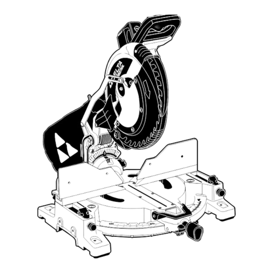
FUNCTIONAL DESCRIPTION FOREWORD Delta Model 36-422L is a high capacity 12" dual bevel compound miter saw equipped with a laser guide and designed to cut wood and non-ferrous metals. This machine is supplied with design features that increase the cutting capacity. - Page 9 ATTACHING THE DUST BAG 1. Attach the dust spout (A) Fig. 3 to the dust port (B). 2. Depress the spring clips (C) Fig. 3 of dust bag (D) and clip the dust bag (D) over the rib of the dust spout (A). MOVING THE CUTTINGHEAD TO THE UP POSITION Push down on the handle (B) Fig.
-
Page 10: Operation
FENCE OPERATION DISCONNECT MACHINE FROM POWER SOURCE. The saw is equipped with two fence sections. Both fence sections, one is shown at (A) Fig. 7, are adjustable and should be placed as close to the blade as possible for all bevel or straight cuts to provide adequate support and for an accurate cut. - Page 11 ROTATING THE TABLE FOR MITER CUTTING DISCONNECT MACHINE FROM POWER SOURCE Fig. 11 Fig. 12 The compound miter saw will cut any angle from a straight 0° cut to 48° right and left. To adjust, place locking knob (A) in the unlocked position as shown in Fig.
- Page 12 TABLE HAZARD ZONE THE AREA INSIDE THE TWO RED LINES (A) FIG. 17 ON THE TABLE IS DESIGNATED AS A HAZARD ZONE. NEVER PLACE YOUR HAND(S) INSIDE THE "TABLE HAZARD ZONE" (WITHIN THE RED LINES) WHILE THE TOOL IS BEING OPERATED. CLAMP ALL WORKPIECES WHICH WOULD CAUSE YOUR HAND(S) TO BE WITHIN SIX INCHES OF THE SAW BLADE.
- Page 13 ADJUSTING 0°, 33.9°, AND 45° BEVEL POSITIVE STOPS The bevel adjustment utilizes a sliding plate (A) Fig. 20, pin (B), and bushing (C) design feature that can be adjusted to fine- adjust the bevel angle. The position of the pin within the bushing is adjustable and, when set, determines the bevel angle. To adjust, loosen the pin locking screws, move to desired location, and tighten securely.
- Page 14 PHILLIPS LASER USE AND ADJUSTMENTS LASER SCREW UNIT The TwinLaser™ laser units are mounted in a housing that is fitted into the upper blade guard of the miter saw (Fig. A). The lasers project a beam of light downward, along both sides and parallel to the saw blade.
- Page 15 CHECK FOR VERTICAL ALIGNMENT 1. The vertical alignment is set correctly when the lines do not move horizontally (sideways) as the saw head is raised and lowered. If vertical alignment is correct jump to “TO SET LEFT AND RIGHT KERF ADJUSTMENT”.
-
Page 16: Adjusting Sliding Fit Between Cuttinghead Arm And Trunnion
If a delay or "skipping" occurs, turn the saw on and off 4 or 5 times. If the condition persists, have the tool serviced by an authorized Delta Machinery service center. -
Page 17: General Cutting Operations
MACHINE USE GENERAL CUTTING OPERATIONS Your machine has the following capacities: Baseboards Vertical at 6” (152 mm), Flat at 9 ” (235 mm) Crown Vertical and Flat at 7 ” (197 mm) 45° Bevel Up to 2”x10” (51 mm x 254 mm) lumber 90°... - Page 18 CUTTING LARGE MATERIAL Occasionally you will encounter a piece of wood a little too large to fit beneath the blade guard. If this occurs, simply place your right thumb on the upper side of the guard and roll the guard up just enough to clear the workpiece. Avoid doing this as much as possible, but if need be, the saw will operate properly and make the bigger cut.
- Page 19 A NEW FEATURE FOR THIS TOOL IS CROWN MOULDING STOPS BUILT INTO THE BASE. DELTA DOES NOT CONSIDER THE CROWN MOULDING STOPS TO BE WORK CLAMPS AND THEY ARE NOT TO BE USED IN THIS MANNER.
-
Page 20: Crown Moulding
NOTE: The above instructions are assuming the angle between the walls is 90°. If you need help cutting crown moulding set at angles other than 90°, see the instruction sheet “CUTTING CROWN MOULDING” on the Delta Machinery web site at www.deltamachinery. -
Page 21: Troubleshooting
Fig. C1 CEILING WALL EDGE EDGE Fig. C3 Fig. C4 TROUBLESHOOTING For assistance with your machine, visit our website at www.deltamachinery.com for a list of service centers or call the DELTA Machinery help line at 1-800-223-7278 (In Canada call 1-800-463-3582). -
Page 22: Maintenance
MAINTENANCE CHANGING THE BLADE DISCONNECT MACHINE FROM POWER SOURCE. NEVER DEPRESS THE SPINDLE LOCK BUTTON WHILE THE BLADE IS UNDER POWER OR COASTING. DO NOT CUT FERROUS METAL (CONTAINING IRON OR STEEL) OR MASONRY OR FIBER CEMENT PRODUCT WITH THIS MITER SAW. To remove the blade: Unplug the saw. -
Page 23: Brush Inspection And Replacement
KEEP MACHINE CLEAN LUBRICATION Periodically blow out all air passages with dry compressed machine Apply household floor paste wax to the table and air. All plastic parts should be cleaned with a soft damp extension table or other work surface weekly. cloth. -
Page 24: Service
Two Year Limited New Product Warranty Delta will repair or replace, at its expense and at its option, any new Delta machine, machine part, or machine accessory which in normal use has proven to be defective in workmanship or material, provided that the customer returns the product prepaid to a Delta factory service center or authorized service station with proof of purchase of the product within two years and provides Delta with reasonable opportunity to verify the alleged defect by inspection. -
Page 25: Español
The following are trademarks of PORTER-CABLE • DELTA (Las siguientes son marcas registradas de PORTER-CABLE • DELTA S.A.) (Les marques suivantes sont des marques de fabriquant de la PORTER-CABLE • DELTA): Auto-Set®, bammer®, B.O.S.S.®, Builder’s Saw®, Contractor’s Saw®, Contractor’s Saw II™, Delta®, DELTACRAFT®, DELTAGRAM™, Delta Series 2000™, DURATRONIC™, Emc²™, FLEX®, Flying Chips™, FRAME SAW®, Grip Vac™, Homecraft®,...
Need help?
Do you have a question about the 36-422L and is the answer not in the manual?
Questions and answers