Table of Contents
Advertisement
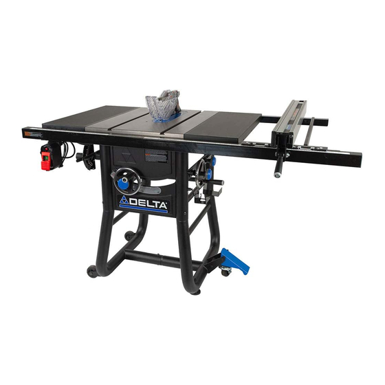
10-inch Contractor Table Saw
Scie de table de 10 pouces (254 mm) pour entrepreneurs
Sierra de mesa de 10 pulgadas (254 mm) para contratista
Français (32)
Español (61)
www.DeltaMachinery.com
Instruction Manual
Manuel d'utilisation
Manual de instrucciones
To reduce risk of serious injury, thoroughly read and comply with all warnings and instructions in this manual and on product.
KEEP THIS MANUAL NEAR YOUR SAW FOR EASY REFERENCE AND TO INSTRUCT OTHERS
36-725 T2
Advertisement
Table of Contents

Related Manuals for Delta 36-725 T2


Summary of Contents for Delta 36-725 T2
- Page 1 Manuel d’utilisation Manual de instrucciones 36-725 T2 To reduce risk of serious injury, thoroughly read and comply with all warnings and instructions in this manual and on product. KEEP THIS MANUAL NEAR YOUR SAW FOR EASY REFERENCE AND TO INSTRUCT OTHERS...
-
Page 2: Table Of Contents
Checking Fence Alignment ..........19 FUNCTIONAL DESCRIPTION SPECIFICATIONS The DELTA #36-725 T2 10-inch Contractor Table Saw is ® designed for portability and high quality performance. It includes: basic machine, sturdy tubular steel stand, integral dust chute, Max depth of cut at 90 degrees: 3-1/8”... -
Page 3: Important Safety Instructions
Improper operation, maintenance or modification of tools or equipment could result in serious injury and/or property damage. If you have any questions or concerns relative to the use of your tool or the contents of this manual, stop using the tool and contact Delta Power Equipment Corporation Customer Care at 1-800-223-7278. -
Page 4: General Power Tool Safety Rules
GENERAL POWER TOOL SAFETY RULES Read all safety warnings, instructions, illustrations and specifications provided with this power tool. Failure to follow all instructions listed below may result in electric shock, fire and/or serious injury. Save all warnings and instructions for future reference. The term “power tool”... - Page 5 TABLE SAW SAFETY RULES Failure to follow these rules may result in serious personal injury. • SEE GENERAL POWER TOOL SAFETY SECTION OF THIS MANUAL. Read entire instruction manual before operating saw. Learning the saw’s proper applications, limitations, and specific potential hazards will greatly minimize the possibility of accidents and injury.
- Page 6 TABLE SAW SAFETY RULES unplug the tool then clear the jam. Jamming the saw blade by the workpiece can cause kickback or stall the motor. Do not remove pieces of cut-off material while the saw is running. The material may become trapped between the fence or inside the saw blade guard and the saw blade pulling your fingers into the saw blade. Turn the saw off and wait until the saw blade stops before removing material.
-
Page 7: Power Connections
PROPOSITION 65 WARNING: Some dust created by power sanding, sawing, grinding, drilling, and other construction activities contains chemicals known to the state of California to cause cancer, birth defects or other reproductive harm. Some examples of these chemicals are: • Lead from lead-based paints •... -
Page 8: Extension Cords
POWER CONNECTIONS IN ALL CASES, MAKE CERTAIN THE RECEPTACLE IN QUESTION IS PROPERLY GROUNDED. IF YOU ARE NOT SURE, HAVE A QUALIFIED ELECTRICIAN CHECK THE RECEPTACLE. This is a grounded, cord-connected tool intended for use on a supply circuit having a nominal voltage of 120 volts. It is intended to for use on a circuit that has an outlet as shown in FIG. -
Page 9: Unpacking
Carefully inspect parts to make sure no damage occurred during familiarize yourself with proper assembly, maintenance and safety procedures. shipping. If any parts are missing, damaged or pre-assembled, do not assemble. Instead, call DELTA Customer Care at 1-800-223- ® Check shipping carton and machine for damage before unpacking. -
Page 10: Hardware Package
UNPACKING Item # HARDWARE PACKAGE Parts List DESCRIPTION (QTY) Item 11. 1/4”-20 x 1/2” hex butt hd screw w/ ¼” spring Parts List washer (5) 1/4”-20 x 1/2” hex hd cap screw w/ ¼” spring washer (2) 1. M8 x 70mm carriage bolt (1) 12. -
Page 11: Fixed Wheels And Stationary Feet
ASSEMBLY FIXED WHEELS AND STATIONARY FEET Attach the two fixed wheels (A) to the left leg using the carriage shoulder bolt as in Figure 2. Screw the adjustable feet (C) into the threaded inserts in the right leg. Lay a scrap piece of 2x4 on the back of the saw, as shown in Figure 3, to prevent damage to the dust chute when righting the saw. -
Page 12: Extension Wings
ASSEMBLY EXTENSION WINGS Attach the extension wings (5) to the Front and Rear rails LEFT EXTENSION LEFT EXTENSION using four 5/16-18 x 1 1/8-inch flat head screws, 5/16 lock WING WING washers, and 5/16-18 hex flange nuts. Attach the extension wings (5) to the table using three 5/16”-18 hex screws with spring washers for each wing. The wings attach from underneath. -
Page 13: Throat Plate
ASSEMBLY THROAT PLATE To install throat plate, lower blade below tabletop, then carefully feed the throat plate, slotted end first, from the front of the table to the rear, keeping the blade centered within the slot on the throat plate. See Figure 11A. The plate should rest within the cavity in the tabletop. Ensure that the throat plate is flush with the top of the table. -
Page 14: Blade Guard
RIP FENCE Attach the handle to the fence cam The Delta #36-725 T2 contractor table saw comes with on-board storage The rip fence slides onto the rear fence rail so that the hook is under for the provided miter gauge, arbor wrench, riving knife push stick the rear rail and rides on the front guide tube. -
Page 15: Adjusting The 90° And 45° Positive Bevel Stops
ASSEMBLY ADJUSTING 90° AND 45° POSITIVE BEVEL STOPS Rotate the blade tilt wheel counterclockwise until it rests on There are positive stops at each end of the bevel range. To ensure accurate cuts, the positive stops must be positioned at exactly at the 45°... -
Page 16: Raising And Lowering The Blade
PREPARING TO CUT RAISING AND LOWERING THE BLADE For most applications, it is recommended that you raise the blade 1/8-inch (3.2mm) to 1/4-inch (6.4mm) above the top surface of the workpiece. Raise or lower the blade with the hand wheel (A) located on the front of the saw ,maximum 45°... -
Page 17: Selecting And Storing Saw Blades
PREPARING TO CUT SELECTING AND STORING SAW BLADES Use only saw blades designed for maximum safe operating Riving knives must be matched to saw blade dimensions in speeds of 3,600 RPM or greater. Only use 10 in. blades order to function effectively. designed for wood cutting. The saw blade furnished with your new saw is a 10-inch Saw blades should always be kept sharp. -
Page 18: Height Settings
PREPARING TO CUT RIVING KNIFE HEIGHT SETTINGS Return the locking cam lever to the locked position. If you have done this properly the riving knife will be aligned with The height of the riving knife should be adjusted based on the the blade. -
Page 19: Using The Miter Gauge
PREPARING TO CUT USING THE MITER GAUGE The miter gauge is equipped with adjustable index stops at 90°, 75°, 60°, 45° and 30°. To set the miter for an angled cut, see Figure 21 and: Loosen the handle (A). Depress the thumb lever (B). Move the body of the miter gauge to the desired angle maximum 30°... -
Page 20: Operation
Each time you use the saw, run through the following The use of attachments and accessories not recommended checklist: by Delta Power Equipment Corporation may result in injury. • Are the power source and power connections adequate Replace or sharpen the anti-kickback fingers when the for the saw? points become dull. -
Page 21: Overload Protection
OPERATION OVERLOAD PROTECTION Your saw is supplied with overload protection. If the motor shuts NOTICE: If the motor continually shuts off due to over- loading, contact a qualified electrician. off or fails to start due o overloading (cutting stock too fast, using a dull blade, using the saw beyond its capacity, etc.) or low voltage, let the motor cool three to five minutes. Then depress the red reset button (B), on the motor under the saw, shown in Figure 23, and restart the saw. -
Page 22: Rip Cuts
OPERATION Use the push stick and any other cutting aids, as needed, RIP CUTS to hold the workpiece against the table and fence, and push the workpiece past the blade. A push stick is included • Rip cutting: Rip cutting is performed predominantly in a with this saw, and instructions are included to make parallel direction with the grain of the wood. -
Page 23: Cross-Cuts
OPERATION CROSSCUTTING a larger workpiece, or attach an auxiliary face to the miter gauge and attach workpiece to auxiliary face, For • Cross cutting: Cross cutting is performed predominantly in a instructions about making auxiliary faces, see Cutting Aids perpendicular direction with the grain of the wood. section on page 28 of this manual. -
Page 24: Compound Miter Cuts
OPERATION COMPOUND MITER CUTS This is a combination of bevel crosscutting and mitering. Refer to Figure 28 and follow the instructions for both bevel crosscutting and mitering. Remember to use the right miter slot for all bevel cuts. 90º LARGE PANEL CUTS Place workpiece supports at the same height as the saw table behind saw to support the cut workpiece, and alongside (s) of saw, as needed. -
Page 25: Using Cutting Aids
OPERATION HEELING (PARALLELING) BLADE TO MITER GAUGE GROOVE • Blade (A) must be parallel to miter gauge groove so that wood does not bind, resulting in kickback. Failure to do so could result in serious personal injury. • To reduce risk of injury from kickback, align rip fence to blade (A) following any blade adjustments. -
Page 26: Push Blocks
CUTTING AIDS AND ACCESSORIES AUXILIARY RIP FENCE FACING Use an auxiliary rip fence facing when needed for special cuts, such as ripping material that is thin enough to slide under the rip fence provided with your saw, or when a taller rip fence is necessary to complete your cut. -
Page 27: Featherboards
CUTTING AIDS AND ACCESSORIES FEATHERBOARD Dimensions for making a typical featherboard are shown in Figure Featherboards are used to keep the work in contact with 34. Make our featherboard from a straight piece of wood that is the fence and table (Figure 34), and help prevent kickback. free of knots and cracks. -
Page 28: Alignment
ALIGNMENT RIVING KNIFE ALIGNMENT WITH THE BLADE This procedure requires a 4mm T-handle hex wrench and straight edge ruler. (Fig.36 b) WARNING: Completely disconnect saw from power source before making any adjustments. Carefully remove throat plate, Loosen the two hex-head screws (A) shown in Figure 36. Using a straight edge ruler, align riving knife with blade body shown in Figure 36 a. -
Page 29: Aligning Fence Parallel To Miter Slot
ALIGNMENT ALIGNING FENCE PARALLEL TO MITER SLOT Move fence adjacent to right miter gauge and secure to the guide tube by lowering the fence clamping lever. If the fence face (A) figure 42, is not parallel to the miter slot (B), raise the clamping lever and lift the fence and place it on the saw table. Adjust the one or both of the set screws (C) 1/4 turn or less. -
Page 30: Maintenance
FIGURE 42 TROUBLESHOOTING For assistance with your machine, visit our website at www.DeltaMachinery.com for a list of service centers or call Delta Power Equipment Customer Care at 1-800-223-7278. FAILURE TO START If your machine fails to start, check to make sure the prongs on the cord plug are making good contact in the receptacle, and check reset button on power switch housing. -
Page 31: Warranty
You can also write to us for information at Delta Power Equipment Corporation, 2651 New Cut Road, Spartanburg, SC 29303 Attention: Technical Service Manager. Be sure to indicate all of the information shown on the nameplate of your saw (model number,...
Need help?
Do you have a question about the 36-725 T2 and is the answer not in the manual?
Questions and answers