Table of Contents
Advertisement
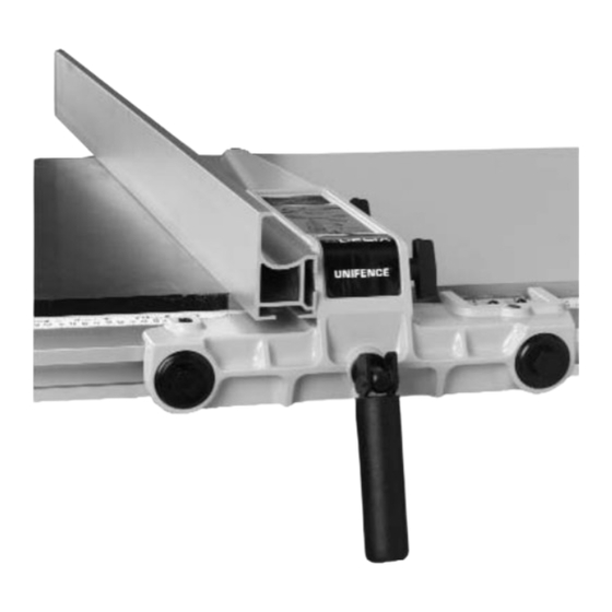
Unifence™ Saw Guide
52" Capacity
(Model 36-889)
PART NO. 422-27-655-0071 (017)
Copyright © 2001 Delta Machinery
To learn more about DELTA MACHINERY
visit our website at: www.deltamachinery.com.
For Parts, Service, Warranty or other Assistance,
1-800-223-7278 (
1-800-463-3582).
please call
In Canada call
Advertisement
Table of Contents

Related Manuals for Delta 36-889


Summary of Contents for Delta 36-889
- Page 1 Unifence™ Saw Guide 52" Capacity (Model 36-889) PART NO. 422-27-655-0071 (017) Copyright © 2001 Delta Machinery To learn more about DELTA MACHINERY visit our website at: www.deltamachinery.com. For Parts, Service, Warranty or other Assistance, 1-800-223-7278 ( 1-800-463-3582). please call In Canada call...
- Page 2 The accessory 34-998 table and shelf for the 36-889 52" Unifence are not included with the 36-889 Unifence ™ Saw Guide and must be ordered separately or a similar table and shelf board must be constructed by following the instructions in this manual.
- Page 3 Fig. 2 Fig. 3 40" 15" Fig. 4...
- Page 4 ASSEMBLING TABLE AND SHELF TO SAW CABINET 1. Remove the right table extension wing and front and rear guide rails from the saw. Fig. 5 2. Lay the table upside down on the floor or bench, as shown in Fig. 5. 3.
- Page 5 Also make sure that the front edge of the adapter (K) does not stick out past the front edge of the saw table. FOR TABLE SAWS OTHER THAN DELTA 8. Assemble table adapter plate (K) Fig. 12, to the right side of the saw table as shown using three 3/4 inch screws, lockwashers and hex nuts (not supplied).
- Page 6 Fig. 15 10. Using a straight edge (S) Fig. 15, make certain the Unifence table surface is level with the saw table by adjusting two leveling screws located on the bottom of Fig. 16 table legs and adjusting angle brackets (T) Fig. 16, use a level, side to side and front to back to make sure the table is level.
-
Page 7: Assembling Unifence Guide Rail To Table
(F). Fig. 20 FOR TABLE SAWS OTHER THAN DELTA 3. Drill two 7/16" holes in the front of the table 1.18" from the top of the table and approximately 2" in from the right and left side of the table. - Page 8 6. Slide the guide rail along until the “0” on the Unifence scale is aligned with the right edge of the saw table. Snug the hex nuts on the saw and extension table but do not tighten at this time. 7.
-
Page 9: Assembling Cursor To Unifence Body
(G) and sliding the stop along the rail to the desired position and re- tighten. 2. Any number of stops, Delta Cat. No. 36-899, can be purchased and installed to provide time saving quick stop adjustment for the Unifence body. - Page 10 ASSEMBLING UNIFENCE BODY TO GUIDE RAIL 1. Turn fence body (A) Fig. 32, upside down and lay it on a table or bench. Pull handle (B) out against fence body. Make certain the surface (C) of clamp bracket is parallel to the face (D) of the fence body, and that the inside edge (E) of the clamp bracket is parallel to surface (F) of the fence body.
-
Page 11: Assembling Fence To Unifence Body
ASSEMBLING FENCE TO UNIFENCE BODY 1. The fence (A) can be assembled to clamp plate (B) in either the horizontal position as shown in Fig. 36, or the vertical position as shown in Fig. 37. Make certain the two lock knobs, one of which is shown at (C), are loose and slide fence (A) onto clamp plate (B) as shown. - Page 12 3. When ripping thin stock, it is sometimes more convenient to use the fence in the horizontal position, as shown in Fig. 40. Fig. 40 4. To move the fence along the guide rail, lift up clamp lever (A), as shown in Fig. 41, slide fence to desired position on the rail, and push down on clamp lever (A) to lock fence in place.
-
Page 13: Ripping With The Unifence
The saw blade guard must be used. On Delta saws, the guard has anti-kickback Fig. 44 fingers to prevent kickback and a splitter to prevent the saw from closing and binding the blade. - Page 14 ADJUSTING FENCE PARALLEL TO MITER GAUGE SLOTS The fence (A) Fig. 48, should be adjusted so it is parallel to miter gage slots (B). To check and adjust, move the fence (A) until the bottom front edge of the fence is in line with the edge of the miter gage slot as shown, and push down on fence clamping lever (C).
-
Page 15: Ripping On Left Side Of Saw Blade
RIPPING ON LEFT SIDE OF SAW BLADE In some cases it may be desirable to use the fence on the left side of the saw blade. This is accomplished by repositioning the fence (A) Figures 52 and 53, fence clamp bar (B) and lock knobs (C) so that the fence (A) will be attached to the right side of the fence body, as shown in Fig. -
Page 16: Using Auxiliary Wood Facing On The Unifence
USING AUXILIARY WOOD FACING ON THE UNIFENCE It is necessary when performing special operations such as when using the moulding cutterhead to add wood facing (A) Fig. 57, to one side of the rip fence as shown. The wood facing is attached to the fence with wood screws through holes drilled in the fence. -
Page 17: Constructing A Push Stick
CONSTRUCTING A PUSH STICK When ripping work less than 4 inches wide, a push stick should be used to complete the feed and could easily be made from scrap material by following the pattern shown. - Page 18 NOTES...
-
Page 19: Parts, Service Or Warranty Assistance
Two Year Limited Warranty Delta will repair or replace, at its expense and at its option, any Delta machine, machine part, or machine accessory which in normal use has proven to be defective in workmanship or material, provided that the customer returns the product prepaid to a Delta factory service center or authorized service station with proof of purchase of the product within two years and provides Delta with reasonable opportunity to verify the alleged defect by inspection. - Page 20 Parts and accessories for Porter-Cable ·Delta products should be obtained by contacting any Porter-Cable·Delta Distributor, Authorized Service Center, or Porter-Cable·Delta Factory Service Center. If you do not have access to any of these, call 800-223-7278 and you will be directed to the nearest Porter-Cable·Delta Factory Service Center. Las Estaciones de Servicio Autorizadas están ubicadas en muchas grandes ciudades.
Need help?
Do you have a question about the 36-889 and is the answer not in the manual?
Questions and answers