Table of Contents
Advertisement
8EAIRS"
Model No. 831.159330
Serial No.
The serial number can be found
in the location shown below.
Write the serial number in the
space above.
Serial Number
CAUTION!
Read all safety precau-
tions and Instructions
In this owner's
manual
and in the accompany-
Ing literature
before
using this equipment.
Keep this owner's
man-
ual In a safe place
for
future reference.
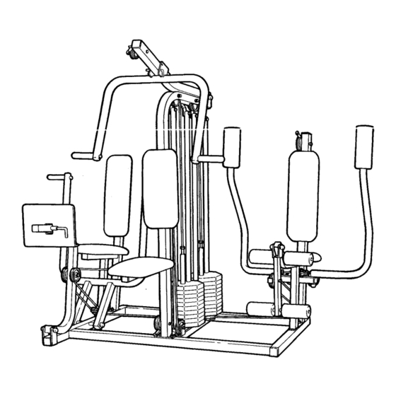
COMPACT
TRAINING
SYSTEM
35+
EXERCISES
200
LBS
CAST
IRON
0 WNER 'S MAN UAL
Advertisement
Table of Contents

Subscribe to Our Youtube Channel
Related Manuals for LIFESTYLER System CXT


Summary of Contents for LIFESTYLER System CXT
- Page 1 8EAIRS" Model No. 831.159330 Serial No. The serial number can be found in the location shown below. Write the serial number in the space above. COMPACT TRAINING SYSTEM EXERCISES CAST IRON Serial Number CAUTION! Read all safety precau- tions and Instructions In this owner's manual and in the accompany-...
- Page 2 TABLE OF CONTENTS IMPORTANT SAFETY PRECAUTIONS ..........BEFORE YOU BEGIN ............... ASSEMBLY ............... CABLE DIAGRAMS ..............USING THE COMPACT TRAINING SYSTEM ........... TROUBLE-SHOOTING AND MAINTENANCE ........... ORDERING REPLACEMENT PARTS .......... Back Cover WARRANTY .............. Back Cover IMPORTANT SAFETY PRECAUTIONS WARNING: To reduce the risk of serious Injury, read the following Important safety precautions before using the compact training system.
- Page 3 Whether your goal is improved cardiovascular fit- ness, a shapely, toned body or dramatic muscle size and strength, the LIFESTYLER SYSTEM CXT will help you to achieve the specific results you want.
- Page 4 ASSEMBLY Assembly requires two people and will take about four hours. Due to the weight of the compact training system, it should be assembled in the place where it will be used. Place all parts of the compact train- ing system in a cleared area and remove the packing materials; do not dispose of the packing materi- als until assembly is completed.
- Page 5 Slide one end of the 265' Cable (54) onto a 3/8" x 2' Bolt (9). (The 265" Cable is the long Cable that has an eyelet on one end, and is threaded on the other end.) Slide a Cable Trap (3) and a Small Pulley (1) onto the Bolt. Insert the Bolt through the indicated bracket on the Press Frame (20) and tighten a 3/8' Nylock Nut (4) onto the Bolt.
- Page 6 Slide a Cable Trap (3) and a Small Pulley (1) onto a 3/8" x 4 1/2" Bolt (13). Route the 265" Cable (54) up around the Small Pulley. Make sure that the Cable is between the Cable Trap and the Small Pulley. Insert the 3/8"...
- Page 7 10. Slide a Cable Trap (3) and a Small Pulley (1) onto a 3/8" x 2" Bolt (9). Route the 265" Cable (54) down around the Small Pulley. Make sure that the Cable is between the Cable Trap and the Small Pulley.
- Page 8 14. Attach a Seat (39) to the Press Frame (20) with two 1/4" x 3/4" Bolts (6). Snap the plastic pin on the lower end of the Large Backrest (37) into the lower hole in the Press Frame (20). Attach the upper end of the Large Backrest to the Frame with a 1/4"...
- Page 9 17. Slide the four Bumpers (45) onto the four Weight Guides (34). Insert the Weight Guides (34) into the indicat- ed holes in the Base (19). Attach the upper ends of the Weight Guides to the brackets the Weight Upright (31) with 3/8"...
- Page 10 Slide a 3/8" Flat Washer (16), one end of the 17" Cable (51) and a Spacer (62) onto a 3/8" x 2 3/4" Bolt (10). Insert the 125" Cable (52) up through the Weight Upright (31) and over a Large Pulley (2) as shown.
- Page 11 23. Insert the 125" Cable (52) through the "1" Plates (43). The ends of the "1"Plates with the three holes should be downward. Slide a Cable Trap (3) and a Small Pulley (1) onto a 3/8" x 4" Bolt (12). Route the 125" Cable (52) over the Small Pulley.
- Page 12 26. Route the 258" Cable (53) under a Small Pulley (1). Attach the Small Pulley to the lower end of the Weight Upright (31) with a 3/8" x 3 1/2" Bolt (11) and3/8" Nylock Nut (4). Make sure that the Cable Is between Indicated pin and the Small Pulley.
- Page 13 30. Insert the Clevis Pin (60) through one of the three holes in the Weight Upright (31). Insert the Hairpin Cotter (61) through the Clevis Pin. Note: The Clevis Pin is very similar to the Leg Lever Axle (not shown). If the Hairpin Cotter does not fit, then you have mistaken the Leg Lever Axle for the Clevis Pin.
- Page 14 Slide a Cable Trap (3) and a Small Pulley onto a 3/8" x 2" Bolt (9). Route the 258" Cable (53) over the Small Pulley. Make sure that the Cable is between the Cable Trap and the Small Pulley. Insert the 3/8" x 2" Bolt (9) through the indi- cated bracket on the Butterfly...
- Page 15 37. Route the 258" Cable (53) around a Small Pulley (1). Attach the Small Pulley to the Butterfly Frame (24) with a 3/8" x 1 3/4" Bolt (8) and 3/8" Nylock Nut (4). Make sure that the Bolt is through the indicated hole. 38.
- Page 16 Insert a 3/8" x 2 3/4" Bolt (10) through indicated hole in the Leg Lever (28). Slide a Small Pulley (1) and a Cable Trap (3) onto the 3/8" x 2 3/4" Bolt (10). Route the 258" Cable (53) up around the Small Pulley. Make sure that the Cable is between Cable Trap and the Small Pulley.
- Page 17 Insert one Pad Tube (71) through Butterfly Frame (24), and one Pad Tube through the Leg Lever (28). Wet the ends of the Pad Tubes (71) with soapy water. Slide the four Small Pads (29) onto the Pad Tubes. Press two Weight Sleeves (72) into each of the twenty Weights...
- Page 18 49. Remove the decals, one at a time, from the decal sheet, and apply them to the compact training system in the locations shown in the drawing below. "CXT HIGH •HANDS CLEAR" •CXT MID PULLEY" "CXT MILITARY "BUTTERFLY CXT" PRESS STATION"...
- Page 19 CABLE DIAGRAMS The cable diagrams show the proper routes of the four cables on the compact training system. The numbers indicate the order in which the cables are routed around the pulleys. Use the diagrams to make sure that the four cables are assembled correctly. 17"...
- Page 20 258" Cable (53) 265" Cable (54) end of the 265" cable is attached to One end of the the weight 265' cable is tube. attached to the bolt.
- Page 21 USING THE COMPACT TRAINING SYSTEM The instructions below describe how each part of the compact training system can be adjusted. the EXERCISE GUIDE accompanying this owner's manual to see how the compact training system should be set up for each individual exercise. CHANGING THE WEIGHT SE'I'FING...
- Page 22 ADJUSTING THEMILITARY PRESSARM For the MILITARY PRESS or REVERSE MILI- TARY PRESS exercises (see the EXERCISE GUIDE), pivot the Military Press Arm (32) so the hole labeled "B" is aligned with the hole in the Military Press Lever (33), and insert the 4 1/4' "L" Pin (41) through the Military Press Arm and the Military Press Lever.
- Page 23 TROUBLE-SHOOTING AND MAINTENANCE Inspect and properly tighten all parts of the compact training system each time you exercise. Replace any worn parts immediately. The compact training system can be cleaned using a damp cloth and mild non-abrasive detergent. Do not use solvents. ADJUSTING THE CABLES If there is too much slack in the cables, the...
- Page 24 ALWAYS GIVE THE FOLLOWING INFORMATION: 1. The MODEL NUMBER of the product (831.1 59330). 2. The NAME of the product (SEARS LIFESTYLER ®SYSTEM CXT compact training system). 3. The PART NUMBER of the part(s) from the PART LIST/EXPLODED DRAWING accompanying...
Need help?
Do you have a question about the System CXT and is the answer not in the manual?
Questions and answers