Table of Contents
Advertisement
Advertisement
Table of Contents

Subscribe to Our Youtube Channel
Related Manuals for LIFESTYLER System 300


Summary of Contents for LIFESTYLER System 300
- Page 1 ® SYSTEM S£ARS o Model No. 831.159422 Serial No. Write the serial number in the space above for reference. Serial Number Decal (Under Seat) EE R E£: HELPLINEI /-800-736-6879 USER'S MANUAL PATENT PENDING SEARS, ROEBUCK AND CO., HOFFMAN ESTATES, IL 60179...
- Page 2 TABLE OF CONTENTS IMPORTANT PRECAUTIONS .............. BEFORE YOU BEGIN ..............ASSEMBLY ................HOW TO USE THE SYSTEM 300 ............WEIGHT RESISTANCE CHART ............TROUBLE-SHOOTING AND MAINTENANCE ..........CABLE DIAGRAMS ..............ORDERING REPLACEMENT PARTS ..........Back Cover LIMITED WARRANTY ............Back Cover Note: A PART IDENTIFICATION CHART and an EXPLODED DRAWING have been attached to the center of this manual.
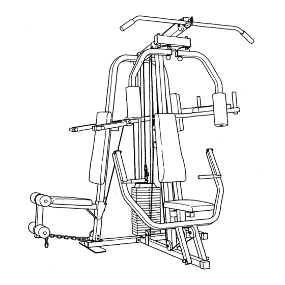
- Page 3 BEFORE YOU BEGIN Thank you for selecting the SEARS ® LIFESTYLER Monday through Saturday, 7 a.m. until 7 p.m. Central SYSTEM 300 Weight System. The versatile SYSTEM Time (excluding holidays). To help us assist you, 300 features an impressive array of weight stations...
- Page 4 ASSEMBLY Due to the size and weight of the SYSTEM 300, it IDENTIFICATION CHART attached to the center of should be assembled in the location where it will be this manual. used. Place all parts of the SYSTEM 300 in a Assembly requires these tools (not included): cleared area and remove the packing materials;...
- Page 5 Attach the Squat Upright (71) to the two indicated 3/8" x 2 3/4" Carriage Bolts (1) in the Stabilizer (69) with two 3/8" Jam Nuts (2). Do not fully tighten the Jam Nuts yet. Tap a 2" x 2" Inner Cap (78) into the Squat Upright (71).
- Page 6 Attach the Frame (80) to the two 3/8" x 2 3/4" Carriage Bolts (1) in the Base (43) with two 3/8" Jam Nuts (2). Do not fully tighten the Jam Nuts yet, Insert the Frame Cap (88) into the indicated end of the Frame (80).
- Page 7 Tap a 1 1/2" x 3" Inner Cap (101) into each side ° of the Butterfly Arm Frame (42). Attach the Butterfly Arm Frame (42) to the Frame (80) with a 3/8" x 3 1/4" Bolt (5) and a 3/8" Jam Nut (2).
- Page 8 10. Make sure that there are two Long 3/4" Flange Bushings (18) in the indicated side of the Butterfly Arm Frame (42). Tap two 1 3/4" x 1 3/4" Inner Caps (24) into the left Butterfly Arm (30) as shown. Slide an Adjustment Bracket (32) onto the axle on the left Butterfly Arm (30).
- Page 9 13. Tap two 1 3/4" x 1 3/4" Inner Caps (24) into the Squat Arm (72). Tap two 1" Round Caps (22) into the Squat Arm (72). 14. Attach the Squat Arm (72) to the VKR Upright (70) with a 3/8" x 3 1/4" Bolt (5) and a 3/8" Jam Nut (2), Do not overtighten the Jam Nut;...
- Page 10 16. Tap a 1" x 1 1/2" Inner Cap (23) into a Handle (26). Tap a 1" Round Cap (22) into the Handle. Apply lubricant to a 3/8" x 2 1/2" Bolt (3). Attach the Handle (26) to the Press Arm (28) with the Bolt and a 3/8"...
- Page 11 20. Feed the Short Cable (44) around one of the 4 1/2" Pulleys (85). Feed the Short Cable (44) up over the 3 1/2" Pulley (12) in the Pivot Arm (91) as shown. _.-44 21. Using two Cable Clips (53), attach the Short ://! V Chain (52) between the Short Cable (44) and the 3/8"...
- Page 12 24. Route the Long Cable (45) under a 3 1/2" Pulley Wide Tab (12). Attach the Pulley and two Pulley Covers (13) to the "U" bracket on the Stabilizer (69) with the 3/8" x 2" Bolt (38) and a 3/8" Jam Nut (2). Make sure that the Pulley Covers are turned so the wide tabs are positioned as shown.
- Page 13 28. Route the Long Cable (45) around the 3 1/2" "V"- Pulley (10). Attach the "V"-Pulley to the bracket on the Frame (80) with a 3/8" x 2 1/2" Bolt (3) and a 3/8" Nylon Locknut (27). 29. Route the Long Cable (45) down around a 3 1/2" Pulley (12).
- Page 14 32. Attach a VKR Arm Pad (75) to the Left VKR Arm (73) with two 1/4" x 2 1/2" Screws (41) and two 1/4" Flat Washers (40). Attach a VKR Arm Pad (75) to the Right VKR Arm (74) in the same manner. 33.
- Page 15 36. Tap a 1 3/4" x t 3/4" Inner Cap (24) into the Leg Lever (62). Attach the Leg Lever (62) to the Squat Seat Frame (11) with a 3/8" x 2 3/4" Bolt (81) and a 3/8" Jam Nut (2). Insert the 3/8"...
- Page 16 40. Insert the Press Seat Frame (36) into the Frame (80). Attach the Press Seat Frame with a 3/8" x 2 1/4" Carriage Bolt (8) and the 3/8" Knob (105). The Press Seat Frame can be attached at any of four heights.
- Page 17 43. Remove the decals from the Decal Sheet (not shown) and apply them to the SYSTEM 300 as shown in the diagram below. HIGH PULLEY RANGE OF LIFESTYLER SQUAT/MILITARY COMBO VERTICAL KNEE RAISE PRESS ARM EXTENSION LOW PULLEY 44. Make sure that all parts are correctly assembled and tightened. Use of the remaining parts will be explained in HOW TO USE THE SYSTEM 300, beginning on page 18 of this manual.
- Page 18 HOW TO USE THE SYSTEM 300 The instructions below describe how each part of the SYSTEM 300 can be adjusted. Refer to the EXERCISE GUIDE accompanying this manual for exercise guidelines, and to see how the SYSTEM 300 should be set up for each exercise.
- Page 19 ATTACHING THE LEG LEVER TO THE LOW PULLEY STATION To use the Leg Lever (62), the Squat Seat (65) must be attached to the Squat Upright (71) (see REMOV- ING AND ATTACHING THE SQUAT SEAT on page 18). Attach the Long Chain (97) to the Long Cable (45) with a Cable Clip (53).
- Page 20 WEIGHT RESISTANCE CHART ACTUAL BUTTERFLY HIGH PULLEY LOW PULLEY SQUAT PRESS WEIGHT ARMS STATION STATION (Lbs.) (Lbs.) (Lbs.) (Lbs.) (Lbs.) 10 Ibs. 40 Ibs. 50 Ibs. 80 Ibs. 90 Ibs. 120 Ibs. 130 Ibs. 200 Ibs. DO NOT USE...
- Page 21 TROUBLE-SHOOTING AND MAINTENANCE Inspect and tighten all parts each time you use the SYSTEM 300. Replace all worn parts immediately (see ORDERING REPLACEMENT PARTS on the back cover of this manual). The SYSTEM 300 can be cleaned using a damp cloth and a mild detergent. Do not use solvents or abrasives. ADJUSTING THE CABLES _----44 If there is too much slack in the cables, they should...
- Page 22 CABLE DIAGRAMS The cable diagrams below and on page 23 show the proper routing of the Short Cable (44) and the Long Cable (45). Use the diagrams to make sure that the two Cables are routed correctly. SHORT CABLE (44) ROUTING gh Pulley 5_Weight Selector...
- Page 23 LONG CABLE (45) ROUTING 1--Low Pulley Station Make sure that the Long Cable is under the Weights (not shown), between the Weight Selector (48) and the indicated Weight Bumpers (47) 1O--Frame...
- Page 24 This chart is provided to help you identify the small parts used in assembly. Note: Some parts may have been pre- assembled for shipping purposes; if you cannot find a part in the parts bags, check the frame to see if it has been pre- assembled.
- Page 25 PART IDENTIFICATION CHART---Model No. 831.159422 F_o89sA This chart is provided to help identify the small parts used in assembly. Some parts have been pre-assembled shipping purposes; if a part cannot be found in the parts bags, check the system frame to see if it has been pre- assembled.
- Page 26 3/8" x 2" Bolt (38)-1 3/8" x 2 1/4" Carriage Bolt (8)-1 _\\\\\\\! (_\\\\\\\\\\\\\\\\\\\I 3/8" x 2 3/4" Carriage Bolt (1)-6 3/8"x 2 3/4" Bolt (81)-6 _\\\\\\\1 _\\\\\\1 5/16" x 2 3/4" Carriage Bolt (59)-1 3/8" x 3" Bolt (7)-2 1/4"...
- Page 27 5/8"x 13/32"Spacer(99)-2 © 1" Round Cap (22)-6 1" x 1 1/2" Inner Cap (23)-2 1/2" x 3/4" Spacer (100)-2 3/4" Retainer Cap (19)-4 © 1 3/4" x I 3/4" Inner Cap (24)-12 1/2" x 1 15/16" Spacer (107)-1 3/4" Retainer (17)-6 3/4"...
- Page 29 EXPLODED DRA WING..Mod, 7ol. _17_;_-'-_9-'_ el No. 831.159422...
- Page 31 PART LISTmModel NO. 831.159422 Ro895A Part Part Qty. Description Qty. Description 122548 3/8" x 2 3/4" Carriage Bolt 120597 Short Foam Pad 119425 3/8" Jam Nut 120586 Pad Tube 013581 3/8" x 2 1/2" Bolt 123385 5/16" x 2 3/4" Carriage Bolt 014132 3/8"...
- Page 32 SE/A/ S' o The model number and serial number of your SEARS LIFESTYLER ® SYSTEM 300 Weight System are listed on a decal attached to the Model No. 831.159422 frame. See the front cover of this manual to find the location of the decal.
Need help?
Do you have a question about the System 300 and is the answer not in the manual?
Questions and answers