
Related Manuals for Perle C-10G-STS


Summary of Contents for Perle C-10G-STS
- Page 1 Perle 10G Media Converter Modules Installation Guide CM-10G-STS C-10G-STS CM-10G-XTS C-10G-XTS CM-10G-XTX C-10G-XTX CM-10G-XTSH C-10G-XTSH CM-10G-XTXH C-10G-XTXH P/N 5500326-10 (Rev C)
- Page 2 Overview This document contains instructions necessary for the installation and operation of the Perle 10G Media Converter modules that are used in conjunction with a Perle Media Converter chassis. Each module contains two pluggable transceiver ports that permit connections of SFP+ fiber, XFP fiber and copper modules. The C model modules are the unmanaged modules and the CM models are the managed modules.
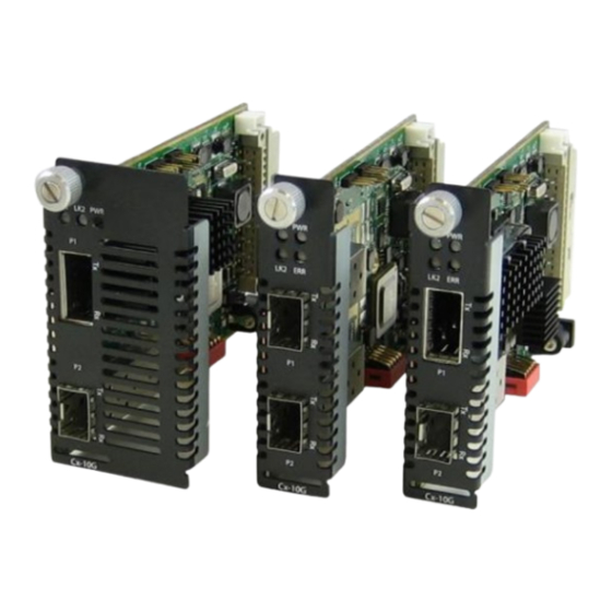
- Page 3 Getting to know your C/CM-10G Media Converter Module Your C/CM-10G Media Converter module package includes: • A C/CM-10G Media Converter module with two pluggable transceiver ports • This guide C/CM-10G Front View Perle 10G Media Converter module Installation Guide...
-
Page 4: Installation
The default switch settings (all switches in the UP position) will work for most installations. The default Auto-Jumper is set to Auto. These are the steps required to configure the Perle 10G Media Converter module: 1. Set the Auto-Jumper switch. (optional) 2. -
Page 5: Installing Modules
Tighten the Captive retainer screw to ensure the module is locked in place. Caution : Observe electrostatic discharge precautions when installing or removing the module(s) from the Chassis. Failure to observe this caution could result in damage to the module(s) and/or chassis Perle 10G Media Converter module Installation Guide... - Page 6 SW: When set to SW (Switch), the module will, at power-up, read the settings of the DIP Switches and use those as its running configuration. It will ignore any configuration information in its flash memory. NOTE: The default jumper setting is Auto Perle 10G Media Converter module Installation Guide...
-
Page 7: Dip Switch Settings
Standard Mode: In this mode, the links can be brought up and down independently of each other. A loss of link on either fiber connection can occur without affecting the other fiber connection Perle 10G Media Converter module Installation Guide... - Page 8 Built In Link Test. Switch 3 determines which port with be put into loopback mode. If the remote device is a supported Perle media converter/module, this unit does not need to be put into test mode and there is no need to set the loopback switch.
- Page 9 Remote-C/CM-10G Configuration All switches in the Up position Note: If the remote Media Converter module is not a supported Perle media converter/ module then the remote Media Converter /module will need to be put into loopback mode. See the documentation that came with that Media Converter module.
-
Page 10: Sequence Of Events
2. Media Converter notifies the remote Media Converter that there is a fault on the Link. 3. Media Converter detects loss of fiber link on receiver RX. 4. Media Converter turns off transmitter (TX). Perle 10G Media Converter module Installation Guide... - Page 11 EPROM on the module and module type. Off: When AutoDetect Mode is turned OFF, the C/CM-10G media converter module will select the alternative setting from that established by the determination above. Perle 10G Media Converter module Installation Guide...
-
Page 12: Operation
Operation Status LED The Perle 10G Media converters modules have three status LEDs located on the front panel of the module. PWR - Power/Test Green On: Power is on and the unit is in normal operation mode. Green blinking slowly: The unit is in test or loopback mode. -
Page 13: Troubleshooting
If unable to get full connectivity with all DIP switches in the UP position, this procedure is recommended for troubleshooting. If the remote device is not a Perle media converter/module the remote device needs to be put into loopback mode. - Page 14 Perle C/CM-10G media converter modules have the ability to automatically put remote supported Perle media converter/ modules into loopback mode. This allows the remote Perle media converter/module to be located in distant or inaccessible locations. The remote Perle media converter/module will remain in loopback mode as long as the tests are in progress.
-
Page 15: Technical Specifications
SFP+ supports C/CM1 (direct attach) interfaces • XFP supports C/CM4 modules Fiber Cabling Requirements 50/125 microns 62.5/125 microns 9/125 microns Note: Please refer the product page on the Perle website for the most up to date specifications.http://www.perle.com/ Perle 10G Media Converter module Installation Guide... -
Page 16: Compliance Information
Warranty / Registration Perle’s standard Lifetime Warranty provides customers with return to factory repairs for Perle products that fail under the conditions of the warranty coverage. Details can be found at: http://www.perle.com/support_services/warranty.shtml Copyright ©...
Need help?
Do you have a question about the C-10G-STS and is the answer not in the manual?
Questions and answers